2AZAM-BAC619INDUCTION COOKTOP
TRAEGER PELLET GRILLS LLC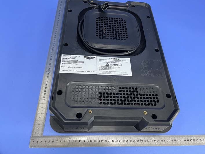
Click to zoom
Application Details
- Equipment Class
- 8CC - Part 18 Consumer Device
- Date of Grant
- May 19, 2021
- Application Purpose
- Original Equipment
- Date of Application
- May 19, 2021
- Equipment Note
- INDUCTION COOKTOP
- Frequency Range
- 0.02000000 - 0.04000000
- Company
- TRAEGER PELLET GRILLS LLC
- Country
- United States
Documents & Files
Document Text
Text extracted from the exhibit documents filed with the FCC. Open a document above to read the original.
Users Manual
OWNER’S MANUAL ???? ???? DOC4??? NEW GRAPHICS FOR INDUCTION HOB 6795 Induction Cooktop OM ENv02.indd 15/8/20 12:00 PM 2 Please read this entire manual before installation, and anyone who uses this induction cooktop should also read the entire manual before operating it. Failure to follow these instructions could result in property damage, bodily injury, or even death. Contact local building or fire officials about restrictions and installation inspection requirements in your area. Save these instructions. If you are installing this unit for someone else, provide this manual for the owner to read and save for future reference. IMPORTANT SAFETY PRECAUTIONS READ ALL INSTRUCTIONS BEFORE INSTALLING AND USING YOUR TRAEGER® INDUCTION COOKTOP To reduce risk of injury or damage to the Induction Cooktop: • Read all instructions before using the cooktop. • Unplug the cooktop from the grill when not in use. • Use the cooktop only in a flat, level position. • As a precaution, persons using a pacemaker should stand back 12" (30 cm) from an operating cooktop. Studies have shown that the induction element will not disrupt a pacemaker. • Keep all credit cards, driver licenses, and other items with a magnetic strip away from an operating cooktop. The cooktop’s magnetic field will damage the information on these strips. • The heating surface is made of a strong, non- porous material. However, should it crack or break, stop using and immediately unplug the cooktop. Cleaning solutions and spills could penetrate the broken cooktop and create a risk of electrical shock. • Do not leave an empty pan on an operating cooktop. • Do not touch the cooking surface. lt remains hot after the cooktop is turned off. • Do not spray controls or outside of cooktop with liquids or cleaning agents. • Do not heat sealed cans or containers, as they may explode. • Do not operate unattended. Closely supervise cooktop if operating in public areas and/or around children. • Do not place any objects inside the air intake or exhaust panels. • Do not attach any accessory objects to the cooktop. SAVE THESE INSTRUCTIONS 6795 Induction Cooktop OM ENv02.indd 25/8/20 12:00 PM 3 TRAEGERGRILLS.COM TABLE OF CONTENTS 2IMPORTANT SAFETY 4GETTING TO KNOW YOUR INDUCTION COOKTOP 5PAIRING YOUR INDUCTION COOKTOP 6COOKING WITH YOUR INDUCTION COOKTOP 10MAINTAINING YOUR INDUCTION COOKTOP 10TROUBLESHOOTING 10SERVICE 11 WARRANTY NEW GRAPHICS FOR INDUCTION HOB 6795 Induction Cooktop OM ENv02.indd 35/8/20 12:00 PM 4 GETTING TO KNOW YOUR INDUCTION COOKTOP PLUG INTO GRILL MONITOR WITH WI-FI Selector Dial Heating Unit Lid COOK WITH EASE Smart Phone Grill Control Induction Cooktop 6795 Induction Cooktop OM ENv02.indd 45/8/20 12:00 PM 5 TRAEGERGRILLS.COM PAIRING YOUR INDUCTION COOKTOP RECOMMENDED TO COMPLETE DURING ON-BOARDING PROCESS. To save time later, it is recommended that you pair your Traeger® Induction Cooktop during the on-boarding process. To ensure the Traeger® Induction Cooktop is ready to pair, plug the cooktop into the grill. This plug is located on the back of the grill. With the grill Main Power switch in the ON (I) position and the Traeger® Induction Cooktop plugged in, Bluetooth will begin broadcasting. If you connected your grill to the Traeger App, the controller will prompt you to begin the pairing process. Select NEXT to proceed. If you did not connect your grill to the App, tap the Menu Icon on the control panel, use the dial to scroll to BLUETOOTH, and press the dial to select. The grill will enter a pairing mode and search for any Traeger Bluetooth devices that are in broadcasting mode. SHOW COOKTOP BEING PLUGGED INTO GRILL SHOW MENU ICON BEING SELECTED/SHOW DIAL SCROLLED TO BLUETOOTH AND PRESSED SHOW PAIRING MODE All Traeger Bluetooth Devices that are emitting a Bluetooth broadcasting signal will appear on the screen. Select COOKTOP and follow the prompts on the screen to complete the pairing process. SHOW THE COOKTOP BEING SELECTED ON SCREEN 12 34 6795 Induction Cooktop OM ENv02.indd 55/8/20 12:00 PM 6 COOKING WITH THE INDUCTION COOKTOP Now you can simplify your meal preparation by doing it all in one place. With the Traeger® Induction Cooktop, you can sear, simmer, sauté, fry, and boil food – right at your grill! COOKING WITH YOUR INDUCTION COOKTOP USE THE RIGHT COOKWARE • FIat base 4 3 /4" to 10 1 /4" (12.1 to 26 cm) in diameter • Ferrous stainless steel, iron, cast iron • Base not flat • Base less than 4 3 /4" (12.1 cm) in diameter • Pottery, glass, aluminum, bronze, or copper cookware • Metal disk on bottom of pan Compatible Incompatible NOTE: Cookware with inferior construction or material may not perform well. Cookware with a larger base diameter can be used; however, only the area of the cookware above the induction coil will heat. The more cookware extends past the coil, the more the overall performance will be reduced. FCC STATEMENT This equipment has been tested and found to comply with Part 18 of FCC Rules. These limits are designed to provide reasonable protection against harmful interference in a residential installation. This equipment generates, uses, and can radiate radio frequency energy and, if not installed and used in accordance with the instructions, may cause harmful interference to radio communications. However, there is no guarantee that interference will not occur in a particular installation. lf this equipment does cause harmful interference to radio or television reception, which can be determined by turning the equipment off and on, the user is encouraged to try to correct the interference by one or more of the following measures: • Reorient or relocate the receiving antenna. • lncrease the separation between the equipment and receiver. • Connect the equipment into an outlet on a circuit different from that to which the receiver is connected. • Consult the dealer or an experienced radio/TV technician for help. To ensure continued compliance, any changes or modifications not expressly approved by the party resp…
Text truncated - open the document above for the full version.
Cover Letter(s)
TRAEGER PELLET GRILLS LLC 1215 E WILMINGTON AVE SUITE 200, SALT LAKE CITY, UT 84106 Date: 2021-05-8 Dear Sir/Madam, We, TRAEGER PELLET GRILLS LLC Hereby declares the following statement for Federal Communications Commission, PCB board, circuit, structure and internal of these model(s) are the same, Only model number is different for these model: Product name: INDUCTION COOKTOP Model no.: BAC619, BAC619-X or BAC619-XX (Suffix X or XX can be digits or letters, will be used for customized models. These customized models will be identical with BAC619 except for functions or color in appearance.) Sincerely, Name/Title: Cyndi Price/Certification Manager Company: TRAEGER PELLET GRILLS LLC Address: 1215 E WILMINGTON AVE SUITE 200, SALT LAKE CITY, UT 84106 Phone: 1-800-872-3437 Fax: 1-800-872-3437 E-Mail: [email protected]
Cover Letter(s)
CONFIDENTIALITY REQUEST for Certification Service in USA Federal Communication Commission Equipment Authorization Division, Application Processing Branch 7435 Oakland Mills Road Columbia, MD 21046 Date:<2021-5-8> Pursuant to Paragraphs §0.457 and 0.459 of the Commission’s Rules (47 C.F.R.) and Section §552(b)(4) of the Freedom of Information Act, we requests confidentiality for the following products: FCC ID Model name 2AZAM-BAC619 BAC619, BAC619-X or BAC619-XX (Suffix X or XX can be digits or letters, will be used for customized models. These customized models will be identical with BAC619 except for functions or color in appearance.) For the product stated above, we request that the following information be held confidential; Exhibits Long-Term Confidentiality Short-Term Confidentiality Short-Term Confidentiality Days External Photos Internal Photos Block Diagram Schematics Test Setup Photos User’s Manual Parts List Tune Up Operational Descriptions The long-term confidentiality exhibits contain our trade secrets and proprietary information that could be of benefit to our competitors. The short-term confidentiality on the basis of ensuring that business sensitive information remains confidential until the actual marketing of our new device. If you have any questions, please feel free to contact me at the address shown below. Sincerely, Name/Title: Cyndi Price/Certification Manager Company: TRAEGER PELLET GRILLS LLC Address: 1215 E WILMINGTON AVE SUITE 200, SALT LAKE CITY, UT 84106 Phone: 1-800-872-3437 Fax: 1-800-872-3437 E-Mail: [email protected]
Cover Letter(s)
TRAEGER PELLET GRILLS LLC 1215 E WILMINGTON AVE SUITE 200, SALT LAKE CITY, UT 84106 Federal Communications Commission Authorization and Evaluation Division Equipment Authorization Branch 7435 Oakland Mills Road Columbia, MD 21046 2021-5-8 To whom it may concern: We, TRAEGER PELLET GRILLS LLC the undersigned, hereby authorize Eurofins Product Service GmbH to act on our behalf in all matters relating to applications for equipment authorization FCC ID: 2AZAM-BAC619 including the signing of all documents related to these matters. Any and all acts carried out by Eurofins Product Service GmbH on our behalf shall have the same effect as acts of our own. We also hereby certify that no party to this application is subject to a denial of benefits, including FCC benefits, pursuant to Section 5301 of the Anti-Drug Abuse Act of 1988, 21 U.S.C. 862. Sincerely, Name/Title: Cyndi Price/Certification Manager Company: TRAEGER PELLET GRILLS LLC Address: 1215 E WILMINGTON AVE SUITE 200, SALT LAKE CITY, UT 84106 Phone: 1-800-872-3437 Fax: 1-800-872-3437 E-Mail: [email protected]
External Photos
FCC ID: 2AZAM-BAC619 TB-RF-074-1.0 Appendix III EUT External Photographs Photo 1 Appearance of EUT Photo 2 Appearance of EUT FCC ID: 2AZAM-BAC619 TB-RF-074-1.0 Photo 3 Appearance of EUT Photo 4 Appearance of EUT FCC ID: 2AZAM-BAC619 TB-RF-074-1.0 Photo 5 Appearance of EUT Photo 6 Appearance of EUT
ID Label/Location Info
FCC ID: 2AZAM-BAC619 TB-RF-074-1.0 Appendix IFCC ID Label FCC ID: 2AZAM-BAC619 TB-RF-074-1.0 Appendix II ID Label Location ID LOCATION
Internal Photos
FCC ID: 2AZAM-BAC619 TB-RF-074-1.0 Appendix IV EUT Internal Photographs Photo 7 Internal of EUT Photo 8 Appearance of PCB FCC ID: 2AZAM-BAC619 TB-RF-074-1.0 Photo 9 Appearance of PCB Photo 10 Appearance of PCB FCC ID: 2AZAM-BAC619 TB-RF-074-1.0 Photo 11 Appearance of PCB Photo 12 Appearance of PCB Bluetooth Antenna
Test Report
Shenzhen Toby Technology Co., Ltd. Report No.: TB-FCC178934 Page: 1 of 16 TB-RF-074-1.0 1/F.,Building 6, Rundongsheng Industrial Zone, Longzhu, Xixiang, Bao'an District, Shenzhen, Guangdong, China Tel: +86 75526509301 Fax: +86 75526509195 FCC Test Report FCC ID: 2AZAM-BAC619 Original Grant Report No. : TB-FCC178934 Applicant : TRAEGER PELLET GRILLS LLC Equipment Under Test (EUT) EUT Name : INDUCTION COOKTOP Model No. : BAC619 Series Model No. : BAC619-X or BAC619-XX (Suffix X or XX can be digits or letters, will be used for customized models. These customized models will be identical with BAC619 except for functions or color in appearance.) Brand Name : TRAEGER Sample ID : 20201022-04-1# Receipt Date : 2021-03-18 Test Date : 2021-03-19 to 2021-05-07 Issue Date : 2021-05-08 Standards : FCC Part 18 Conclusions : PASS In the configuration tested, the EUT complied with the standards specified above, The EUT technically complies with the FCC requirements. Test/Witness Engineer : Rebeca Engineer Supervisor : Ivan Su Engineer Manager : Ray Lai This report details the results of the testing carried out on one sample. The results contained in this test report do not relate to other samples of the same product. The manufacturer should ensure that all products in series production are in conformity with the product sample detailed in the report. Report No.: TB-FCC178934 Page: 2 of 16 TB-RF-074-1.0 Contents CONTENTS ............................................................................................................................................. 2 1. GENERAL INFORMATION ABOUT EUT ............................................................................. 4 1.1 Client Information ................................................................................................................. 4 1.2 General Description of EUT (Equipment Under Test) ................................................... 4 1.3 Block Diagram Showing the Configuration of System Tested ...................................... 4 1.4 Description of Support Units .............................................................................................. 5 1.5 Description of Test Mode .................................................................................................... 5 1.6 Test Location ........................................................................................................................ 5 2. TEST SUMMARY ....................................................................................................................... 6 3. TEST SOFTWARE ..................................................................................................................... 6 4. TEST EQUIPMENT .................................................................................................................... 6 5. CONDUCTED EMISSION TEST ............................................................................................. 7 5.1 Test Standard and Limit ...................................................................................................... 7 5.2 Test Setup ............................................................................................................................. 7 5.3 Test Procedure ..................................................................................................................... 8 5.4 Deviation ............................................................................................................................... 8 5.5 Test Data ............................................................................................................................... 8 6. RADIATED EMISSION TEST .................................................................................................. 9 6.1 Test Standard and Limit ...................................................................................................... 9 6.2 Test Setup ............................................................................................................................. 9 6.3 Test Procedure ..................................................................................................................... 9 6.4 Deviation ............................................................................................................................. 10 6.5 Test Data ............................................................................................................................. 10 ATTACHMENT A-- CONDUCTED EMISSION TEST DATA ....................................................... 11 ATTACHMENT B-- RADIATED EMISSION TEST DATA ............................................................ 13 Report No.: TB-FCC178934 Page: 3 of 16 TB-RF-074-1.0 Revision History Report No. Version Description Issued Date TB-FCC178934 Rev.01 Initial issue of report 2021-05-08 Report No.: TB-FCC178934 Page: 4 of 16 TB-RF-074-1.0 1. General Information about EUT 1.1 Client Information Applicant : TRAEGER PELLET GRILLS LLC Address : 1215 E WILMINGTON AVE SUITE 200, SALT LAKE CITY, UT 84106 Manufacturer : Luxine(Xi'an)Electronics Co.,LTD. Address : 29th, 3rd Shanglinyuan Rd, Hi-tech Development Zone, Xi'an, China 1.2 General Description of EUT (Equipment Under Test) EUT Name : INDUCTION COOKTOP Models No. : BAC619, BAC619-X or BAC619-XX (Suffix X or XX can be digits or letters, will be used for customized models. These customized models will be identical with BAC619 except for functions or color in appearance.) Brand Name : TRAEGER Power Supply : Input: AC 120V 60Hz 1410W Working Frequency : 20KHz~40KHz Note: For a more detailed features description, please refer to the manufacturer’s specifications or the User’s Manual. 1.3 Block Diagram Showing the Configuration of System Tested EUT Power Supply Report No.: TB-FCC178934 Page: 5 of 16 TB-RF-074-1.0 1.4 Description of Support Units The EUT has been tested with water up to 80% of the maximum capacity of the boiler. 1.5 Descripti…
Text truncated - open the document above for the full version.
Test Setup Photos
FCC ID: 2AZAM-BAC619 TB-RF-074-1.0 Appendix V EUT Test Photographs Photo of Setup for Radiated Emission Photo of Setup for Conducted Emission -----END OF REPORT-----
Contact Information
Applicant
Chuck Benson(Certification Manager)
Test Firm
Shenzhen Toby Technology Co., Ltd.Ray Lai
Technical Specifications
| # | Rule Parts | Frequency Range | Power Output |
|---|---|---|---|
| 1 | 18 | 0.02 MHz - 0.04 MHz | - |