2AZCME380-0001EverMesh Module
EverCharge Inc.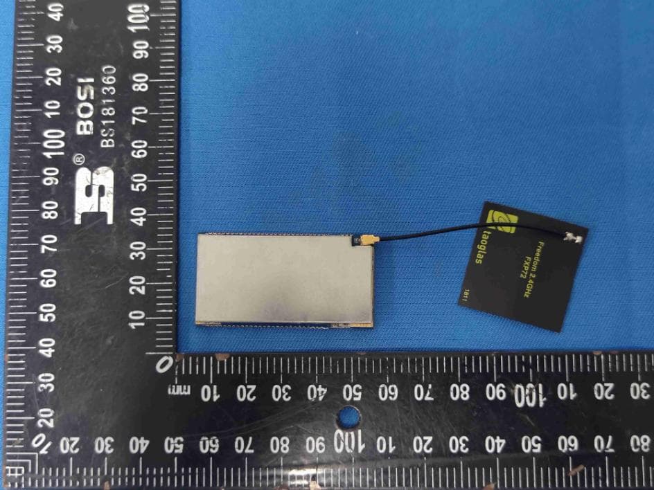
Click to zoom
Application Details
- Equipment Class
- DTS - Digital Transmission System
- Date of Grant
- May 31, 2021
- Application Purpose
- Original Equipment
- Date of Application
- May 31, 2021
- Equipment Note
- EverMesh Module
- Frequency Range
- 2412.00000000 - 2462.00000000
- Company
- EverCharge Inc.
- Country
- United States
Documents & Files
Document Text
Text extracted from the exhibit documents filed with the FCC. Open a document above to read the original.
Users Manual
Communicate with the sincere and open world!! GainStrong Industry Co.,Ltd. http://www.gainstrong.cn Tell:+86-755-81720165 [email protected] 1 EverMesh Module Specification Version 1.0.0 Author:WSY March 31, 2021 Communicate with the sincere and open world!! GainStrong Industry Co.,Ltd. http://www.gainstrong.cn Tell:+86-755-81720165 [email protected] 2 Rev. Date Contents of Revision Change Remark 1.0.0 2020-3-31 release WSY FCC Radiation Exposure Statement FCC standards: FCC CFR Title 47 Part 15 Subpart C Section 15.247 External Antenna with gain ANT: 5dBi FCC Regulatory Compliance: This device complies with Part 15 of the FCC Rules. Operation is subject to the following two conditions: (1) this device may not cause harmful interference, and (2) this device must accept any interference received, including interference that may cause undesired operation. Note: This equipment has been tested and found to comply with the limits for a Class B digital device, pursuant to Part 15 of the FCC Rules. These limits are designed to provide reasonable protection against harmful interference in a residential installation. This equipment generates, uses and can radiate radio frequency energy and, if not installed and used in accordance with the instructions, may cause harmful interference to radio communications. However, there is no guarantee that interference will not occur in a particular installation. If this equipment does cause harmful interference to radio or television reception, which can be determined by turning the equipment off and on, the user is encouraged to try to correct the interference by one or more of the following measures: -- Reorient or relocate the receiving antenna. -- Increase the separation between the equipment and receiver. -- Connect the equipment into an outlet on a circuit different from that to which the receiver is connected. -- Consult the dealer or an experienced radio/TV technician for help. If power exceeds the limit and the distance(Over 20cm distance in actual use between the device and user) is compliance with the requirement Warning: changes or modifications not expressly approved by the party responsible for compliance could void the user’s authority to operate the equipment. RF Exposure Compliance: This equipment complies with FCC radiation exposure limits set forth for an uncontrolled environment. This equipment should be installed and operated with a minimum distance of 20cm between the radiator and any part of your body. Notice to OEM integrator If the FCC ID is not visible when the module is installed inside another device, then the outside of the device into which the module is installed must also display a label referring to the enclosed module. The end product shall haves the words “Contains Transmitter Module FCC ID: 2AZCME380-0001”. The device must be professionally installed. The intended use is generally not for the general public. It is generally for industry/commercial use. The connector is within the transmitter enclosure and can only be accessed by disassembly of the transmitter that is not normally required. The user has no access to the connector. Installation must be controlled. Installation requires special training. Any company of the host device which installs this modular with unlimited modular approval should perform the test of radiated & conducted emission and spurious emission, etc. according to FCC part 15C: 15.247 and15.207, 15B Class B requirement, only if the tests result comply with FCC part 15C: 15.247 and15.207, 15B Class B requirement, then the host can be sole legally. When the module is installed inside another device, the user manual of the hose contain below 1) This device may not cause harmful interference. 2) This device must accept any interference received, including interference that may cause undesired operation Communicate with the sincere and open world!! GainStrong Industry Co.,Ltd. http://www.gainstrong.cn Tell:+86-755-81720165 [email protected] 3 1.INTRODUCTION EverMesh is a highly integrated and cost effective IEEE 802.11n 1x1 2.4 GHz Systemon-a- Chip(SoC) for wireless local area network(WLAN) AP and router module. EverMesh includes a MIPS 24K processor and integrated serial Flash, DDR2, two-port IEEE 802.3 Ethernet Switch with MAC/PHY, one USB 2.0 interface , I2S/SPDIF-Out audio interface, SLIC VOIP/PCM interface, UART, and GPIOs that can be used for LED controls or other general purpose interface configurations. EverMesh is designed for smart home deice, wifi hard disk, WiFi router board, remote monitoring, remote video, Industrial control DIY and so on EverMesh power consumption is very low,usually no more than 0.4W, suitable for battery products, it has a 150M wireless transmission rate, up to 21 gpios. All can be defined for input or output. Communicate with the sincere and open world!! GainStrong Industry Co.,Ltd. http://www.gainstrong.cn Tell:+86-755-81720165 [email protected] 4 2.CHARACTERISTICS ◆CPU: AR9331 400Mhz MIPS core ◆RAM: 64M DDR2 RAM ◆Flash: 16M SPI flash (4/8/32m option) ◆Wireless speed: 150Mbps ◆General GPIO: 21 (except TX, RX) ◆USB: Usb 2.0 master interface, support USB hub extension ◆Power supply voltage: 3.3V. ◆Port: 1WAN and 1LAN 10/100Mbps network interface ◆Antenna: the built-in PCB /IPX external antenna. ◆Debug: serial debugging interface has been out. ◆Board Power: 0.5W ◆Product size: 27.5 * 51.4MM +- 0.1mm Communicate with the sincere and open world!! GainStrong Industry Co.,Ltd. http://www.gainstrong.cn Tell:+86-755-81720165 [email protected] 5 3.PINS Communicate with the sincere and open world!! GainStrong Industry Co.,Ltd. http://www.gainstrong.cn Tell:+86-755-81720165 [email protected] 6 Pin No Name GPIO state spec 1 GND GROUND 2 EX_ANT disconnected Extenal Antenna reserved 3 GND GROUND 4 GPIO12 10K GND I/O I2S_MICIN/UART_CTS 5 GND GROUND 6 GPIO26 Floating ouput I/O 7 GPIO27/SYS_LED 3K led 3.3v output I/O 8 GPIO11 1K 100PF GND input I/O Reset button I2S_…
Text truncated - open the document above for the full version.
Attestation Statements
Compliance list INTEGRATION INSTRUCTIONS for 996369 D03 OEM the and 996369 D03 OEM by Sections 2.2 through 2.10. Requirement Yes N/A Comment 2.2 List of applicable FCC rules List the FCC rules that are applicable to the modular transmitter. These are the rules that specifically establish the bands of operation, the power, spurious emissions, and operating fundamental frequencies. DO NOT list compliance to unintentional-radiator rules (Part 15 Subpart B) since that is not a condition of a module grant that is extended to a host manufacturer. See also Section 2.10 below concerning the need to notify host manufacturers that further testing is required.3 YES Refer to instruction FCC standards: FCC CFR Title 47 Part 15 Subpart C Section 15.247 2.3 Summarize the specific operational use conditions Describe use conditions that are applicable to the modular transmitter, including for example any limits on antennas, etc. For example, if point-to-point antennas are used that require reduction in power or compensation for cable loss, then this information must be in the instructions. If the use condition limitations extend to professional users, then instructions must state that this information also extends to the host manufacturer’s instruction manual. In addition, certain information may also be needed, such as peak gain per frequency band and minimum gain, specifically for master devices in 5 GHz DFS bands. YES Refer to instruction The module is limited to the following antenna: Antenna Type: External Antenna Antenna Gain: 5dBi 2.4 Limited module procedures If a modular transmitter is approved as a “limited module,” then the module manufacturer is responsible for approving the host environment that the limited module is used with. The manufacturer of a limited module must describe, both in the filing and in the installation instructions, the alternative means that the limited module manufacturer uses to verify that the host meets the necessary requirements to satisfy the module limiting conditions. A limited module manufacturer has the flexibility to define its alternative method to address the conditions that limit the initial approval, such as: shielding, minimum NO signaling amplitude, buffered modulation/data inputs, or power supply regulation. The alternative method could include that the limited module manufacturer reviews detailed test data or host designs prior to giving the host manufacturer approval. This limited module procedure is also applicable for RF exposure evaluation when it is necessary to demonstrate compliance in a specific host. The module manufacturer must state how control of the product into which the modular transmitter will be installed will be maintained such that full compliance of the product is always ensured. For additional hosts other than the specific host originally granted with a limited module, a Class II permissive change is required on the module grant to register the additional host as a specific host also approved with the module. 2.5 Trace antenna designs For a modular transmitter with trace antenna designs, see the guidance in Question 11 of KDB Publication 996369 D02 FAQ – Modules for Micro-Strip Antennas and traces. The integration information shall include for the TCB review the integration instructions for the following aspects: layout of trace design, parts list (BOM), antenna, connectors, and isolation requirements.4 a) Information that includes permitted variances (e.g., trace boundary limits, thickness, length, width, shape(s), dielectric constant, and impedance as applicable for each type of antenna); b) Each design shall be considered a different type (e.g., antenna length in multiple(s) of frequency, the wavelength, and antenna shape (traces in phase) can affect antenna gain and must be considered); c) The parameters shall be provided in a manner permitting host manufacturers to design the printed circuit (PC) board layout; d) Appropriate parts by manufacturer and specifications; e) Test procedures for design verification; and No f) Production test procedures for ensuring compliance. The module grantee shall provide a notice that any deviation(s) from the defined parameters of the antenna trace, as described by the instructions, require that the host product manufacturer must notify the module grantee that they wish to change the antenna trace design. In this case, a Class II permissive change application is required to be filed by the grantee, or the host manufacturer can take responsibility through the change in FCC ID (new application) procedure followed by a Class II permissive change application. 2.6 RF exposure considerations It is essential for module grantees to clearly and explicitly state the RF exposure conditions that permit a host product manufacturer to use the module. Two types of instructions are required for RF exposure information: (1) to the host product manufacturer, to define the application conditions (mobile, portable – xx cm from a person’s body); and (2) additional text needed for the host product manufacturer to provide to end users in their end-product manuals. If RF exposure statements and use conditions are not provided, then the host product manufacturer is required to take responsibility of the module through a change in FCC ID (new application). YES Refer to instruction The modular can be installed or integrated in mobile or fix devices only. This modular cannot be installed in any portable device. This modular complies with FCC RF radiation exposure limits set forth for an uncontrolled environment. This transmitter must not be co-located oroperating in conjunction with any other antenna or transmitter. This modular must be installed and operated with a minimum distance of 20 cm betweenthe radiator and user body. 2.7 Antennas A list of antennas included in the application for certification must be provided in the instructions. For modular transmitters approved as limited modules, all applicable professional in…
Text truncated - open the document above for the full version.
Cover Letter(s)
EverChargeInc. Office of EngineeringTechnology FederalCommunicationsCommission 7435 OaklandMills Road Columbia,MD 21046 USA Date: 2021-05-26 Subject;Requestfor Long Term Confidentiality FCC ID: 2AZCME380-0001 To WhomIt May Concern, Pursuantto the provisionsof the Commission’s rules Title 47 Sections§0.457 and §0.459,we are requestingthe Commissionto withholdthe followingattachment(s)as confidential documentsfrom public disclosureindefinitely. Thesedocumentscontaindetailedsystemand equipmentdescriptionsand are consideredas proprietaryinformationin operationof the equipment.The public disclosureof these documents might be harmfulto our companyand would give competitorsan unfair advantagein the market. SchematicDiagram Block Diagram Parts List OperationalDescription Tune-upProcedure It is our understandingthat all measurementtest reports,FCC ID label formatand correspondenceduringthe certificationreviewprocesscannotbe grantedas confidential documentsand this informationwill be availablefor public reviewonce the grant of equipment authorizationis issued. Sincerely, Signature: Name:JasonAppelbaum Title: Compliance
Cover Letter(s)
EverChargeInc. 548MarketSt#31647SanFrancisco,CA94104UnitedStates AgentAuthorization Company:EverChargeInc. Address:548MarketSt#31647SanFrancisco,CA94104UnitedStates ProductName:EverMeshModule ModelNumber(s):E380-0001 ProductDescription:EverMeshModule WeauthorizeMiCOMLabsInc.,575BoulderCourt,Pleasanton,California94566,USA, toactonourbehalfonallmattersconcerningthecertificationofabovenamed equipment. WedeclarethatMiCOMLabsInc.isallowedtoforwardallinformationrelatedtothe approvalandcertificationofequipmenttotheregulatoryagenciesasrequiredandto discussanyissuesconcerningtheapprovalapplication.Anyandallactscarriedoutby MiCOMLabsonourbehalfshallhavethesameeffectasactsofourown. Signature:Date:2021-05-26 Name:JasonAppelbaum Title:Compliance Company:EverChargeInc.
Cover Letter(s)
EverCharge Inc. FCC Modular Approval Request Rev 3.0 Federal Communications Commission Equipment Authorization Division 7435 Oakland Mills Road Columbia, MD 21046 USA Date: 2021-05-26 Subject: EverMesh Module Company name: EverCharge Inc. FCC ID: 2AZCME380-0001 Dear Sir/Madam, This letter includes the FCC application requirements for Modular Transmitter Approv al Request for;- FCC KDB 996369 D01 ‘Module Certification Guide v02; and FCC KDB 996369 D03 OEM Manual v01 In accordance with 47CFR 15.212 Modular Transmitters and KDB 996369 D01 ‘Module Equip Auth Guide v02’. FCC ID: 2AZCME380-0001 has been examined against the following requirements. Requir ement per 15.212 and KDB 996369 D01 Explanation from Grantee (do not write y es/no, but explain why product complies/ how it is achieved) The radi o elements must have the radio frequency circuitry shielded. Physical components and tuning capacitor(s) may be located external to the shield, but must be on the module assembly. The modular have RF own shielding The modu le must have buffered modulation/data inputs to ensure that the device will comply with Part 15 requirements with any type of input signal. The modular transmitter have buffered modulation/data inputs The modu le must contain power supply regulation on the module. The modular transmitter have its own power supply regulation. The modu le must contain a permanently attached antenna, or contain a unique antenna connector, and be marketed and operated only with specific antenna(s), per §§ 15.203, 15.204(b), 15.204(c), 15.212(a), 2.929(b). The modular has a External Antenna, which has a unique antenna connector. T h e mod u le must demonstrate compliance in a stand-alone configuration. The module compliance in a stand-alone configuration. The modu le must be labeled with its permanently affixed FCC ID label, or use an electronic display (see KDB Publication 784748). The FCC identification number can put on the modular with either a permanently affixed label The module m ust comply with all specific rules applicable to the transmitter, including all the conditions provided in the integration instructions by the grantee. The instructions will be provided and apply to a complete transmitter and comply with specific rule. The module must comply with RF exposure requirements The total power density of modular transmitter final configuration comply with FCC RF Exposure FCC Modular Approval Request Rev 3.0 Date: 2021-05-26 Name: Jason Appelbaum Title: Compliance Signature of applicant
External Photos
Page 1 of 1 Appendix B: Photographs of EUT Product: EverMesh Module Model: E380-0001 External Photos Antenna
ID Label/Location Info
LabelArtworkandLocation Model:E380-0001 Label: Size:L*W=52*26mm Location
Internal Photos
Page 1 of 2 Appendix B: Photographs of EUT Product: EverMesh Module Model: E380-0001 Internal Photos Page 2 of 2
RF Exposure Info
Maximum Permissible Exposure Applicable Standard According to §1.1307(b), systems operating under the provisions of this section shall be operated in a manner that ensure that the public is not exposed to radio frequency energy level in excess of the Commission’s guideline. Remark: 1) The maximum output power for antenna is 17.41dBm (55.08mW) at 2437MHz, 5dBi antenna gain(with 3.16 numeric antenna gain.) 2) For mobile or fixed location transmitters, no SAR consideration applied. The minimum separation generally be used is at least 20cm, even if the calculation indicate that the MPE distance would be lesser. Maximum Permissible Exposure output power= 55.08mW Numeric Antenna gain= 3.16 Substituting the MPE safe distance using d=20cm into above equation. Yields: S=0.000199*P*G Where P=Power in mW G=Numeric antenna gain S=Power density in mW/cm 2 Power density= 0.034637mW/cm 2 (For mobile or fixed location transmitters, the maximum power density is 1.0 mW/cm 2 even if the calculation indicates that the power density would be larger.)
Test Report
Hotline: 400-6611-140 Tel: 86-755-27673339 Fax: 86-755-27673332 http://www.tct-lab.com TEST REPORT FCC ID: 2AZCME380-0001 Product: EverMesh Module Model No.: E380-0001 Additional Model No.: N/A Trade Mark: N/A Report No.: TCT210326E022 Issued Date: May 21, 2021 Issued for: EverCharge Inc. 548 Market St #31647 San Francisco, CA 94104 United States Issued By: Shenzhen Tongce Testing Lab TCT Testing Industrial Park, Fuqiao 5th Industrial Zone, Fuhai Street, Bao'an District, Shenzhen, Guangdong, 518103, People's Republic of China TEL: +86-755-27673339 FAX: +86-755-27673332 Note: This report shall not be reproduced except in full, without the written approval of Shenzhen Tongce Testing Lab This document may be altered or revised by Shenzhen Tongce Testing Lab personnel only, and shall be noted in the revision section of the document. The test results in the report only apply to the tested sample. Report No.: TCT210326E022 Page 2 of 88 Hotline: 400-6611-140 Tel: 86-755-27673339 Fax: 86-755-27673332 http://www.tct-lab.com TABLE OF CONTENTS 1. Test Certification ..................................................................................... 3 2. Test Result Summary .............................................................................. 4 3. EUT Description ....................................................................................... 5 4. General Information ................................................................................. 7 4.1. Test environment and mode ................................................................................. 7 4.2. Description of Support Units ................................................................................ 7 5. Facilities and Accreditations .................................................................. 9 5.1. Facilities ................................................................................................................. 9 5.2. Location ................................................................................................................. 9 5.3. Measurement Uncertainty ..................................................................................... 9 6. Test Results and Measurement Data ................................................... 10 6.1. Antenna requirement .......................................................................................... 10 6.2. Conducted Emission ........................................................................................... 11 6.3. Maximum Conducted (Average) Output Power ................................................ 15 6.4. Emission Bandwidth ........................................................................................... 16 6.5. Power Spectral Density ....................................................................................... 17 6.6. Conducted Band Edge and Spurious Emission Measurement ....................... 18 6.7. Radiated Spurious Emission Measurement ...................................................... 20 Appendix A: Test Result of Conducted Test Appendix B: Photographs of Test Setup Appendix C: Photographs of EUT Report No.: TCT210326E022 Page 3 of 88 Hotline: 400-6611-140 Tel: 86-755-27673339 Fax: 86-755-27673332 http://www.tct-lab.com 1. Test Certification Product: EverMesh Module Model No.: E380-0001 Additional Model No.: N/A Trade Mark: N/A Applicant: EverCharge Inc. Address: 548 Market St #31647 San Francisco, CA 94104 United States Manufacturer: Shenzhen Gainstrong Technology Co., Ltd. Address: 4/F, Building B, Hengmingzhu Industrial Park, Qian Jin Road 2, Baoan District, Shenzhen, Guangdong, China Date of Test: Mar. 29, 2021 – May 20, 2021 Applicable Standards: FCC CFR Title 47 Part 15 Subpart C Section 15.247 FCC KDB 558074 D01 15.247 Meas Guidance v05r02 ANSI C63.10:2013 The above equipment has been tested by Shenzhen Tongce Testing Lab and found compliance with the requirements set forth in the technical standards mentioned above. The results of testing in this report apply only to the product/system, which was tested. Other similar equipment will not necessarily produce the same results due to production tolerance and measurement uncertainties. Tested By: Date: May 20, 2021 Aaron Mo Reviewed By: Date: May 21, 2021 Beryl Zhao Approved By: Date: May 21, 2021 Tomsin Report No.: TCT210326E022 Page 4 of 88 Hotline: 400-6611-140 Tel: 86-755-27673339 Fax: 86-755-27673332 http://www.tct-lab.com 2. Test Result Summary Requirement CFR 47 Section Result Antenna requirement §15.203/§15.247 (c) PASS AC Power Line Conducted Emission §15.207 PASS Conducted Peak Output Power §15.247 (b)(3) PASS 6dB Emission Bandwidth §15.247 (a)(2) PASS Power Spectral Density §15.247 (e) PASS Band Edge §15.247(d) PASS Spurious Emission §15.205/§15.209 PASS Note: 1. PASS: Test item meets the requirement. 2. Fail: Test item does not meet the requirement. 3. N/A: Test case does not apply to the test object. 4. The test result judgment is decided by the limit of test standard. Report No.: TCT210326E022 Page 5 of 88 Hotline: 400-6611-140 Tel: 86-755-27673339 Fax: 86-755-27673332 http://www.tct-lab.com 3. EUT Description Product: EverMesh Module Model No.: E380-0001 Additional Model No.: N/A Trade Mark: N/A Operation Frequency: 2412MHz~2462MHz (802.11b/802.11g/802.11n(HT20)) 2422MHz~2452MHz (802.11n(HT40)) Channel Separation: 5MHz Number of Channel: 11 for 802.11b/802.11g/802.11n(HT20) 7 for 802.11n(HT40) Modulation Technology (IEEE 802.11b): Direct Sequence Spread Spectrum (DSSS) Modulation Technology (IEEE 802.11g/802.11n): Orthogonal Frequency Division Multiplexing(OFDM) Data speed (IEEE 802.11b): 1Mbps, 2Mbps, 5.5Mbps, 11Mbps Data speed (IEEE 802.11g): 6Mbps, 9Mbps, 12Mbps, 18Mbps, 24Mbps, 36Mbps, 48Mbps, 54Mbps Data speed (IEEE 802.11n): Up to 150Mbps Antenna Type: External Antenna Antenna Gain: 5dBi Power Supply: DC 3.3V Note: The antenna gain listed in this report is provided by applicant, and the test laboratory is not r…
Text truncated - open the document above for the full version.
Test Setup Photos
Page 1 of 2 Appendix A: Photographs of Test Setup Product: EverMesh Module Model: E380-0001 Radiated Emission Page 2 of 2 Conducted Emission
Contact Information
Applicant
Jason Appelbaum
Technical Contact
Test Firm
SHENZHEN TONGCE TESTING LABBeryl Zhao
[email protected]+8675527208735
Technical Specifications
| # | Rule Parts | Frequency Range | Power Output |
|---|---|---|---|
| 1 | 15C | 2.41 GHz - 2.46 GHz | 55.10 mW |