2AZCX-SLEEPHALOSleepHalo
Angel Electronics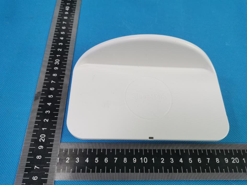
Click to zoom
Application Details
- Equipment Class
- DCD - Part 15 Low Power Transmitter Below 1705 kHz
- Date of Grant
- Apr 26, 2021
- Application Purpose
- Original Equipment
- Date of Application
- Apr 26, 2021
- Equipment Note
- SleepHalo
- Frequency Range
- 0.11100000 - 0.17500000
- Company
- Angel Electronics
- Country
- United Kingdom
Documents & Files
Document Text
Text extracted from the exhibit documents filed with the FCC. Open a document above to read the original.
Users Manual
Before using your SleepHalo™ we recommend reading this guide to prevent any damage that could occur due to misuse. We also recommend registering your product on our website to activate your 2 year warranty. Visit: www.sleephalo.com/register Package Contents Compatibility for Wireless Charging SleepHalo™ has been designed to be compatible with Qi enabled phones. A list can be found on our website. If your phone is not wireless compatible it can still be used with your existing wired charger by placing the plugged-in phone onto SleepHalo™. You will then benefit from the radiation protection offered by SleepHalo™. SleepHalo™ Charger Base Radiation Shield LED Indicator Power Adapter (UK) 1M Cable SleepHalo™ User Manual V1.1 E&OE P a g e 1 o f 6 Connecting your SleepHalo™ Decide which side of the bed you wish to place your SleepHalo™, noting that the raised protection shield should be between you and the phone. On the underside of the product you can route the power cable in 2 directions. Choose which route is best, plug in the connector to the power port and clip the cable through the rebated area. Connect SleepHalo™ USB connector into the power adapter. Plug SleepHalo™ power adapter into a wall socket. Power Port Cable clipped into rebate in base. Non-slip feet avoid SleepHalo™ slipping or scratching the surface it is placed on. SleepHalo™ User Manual V1.1 E&OE P a g e 2 o f 6 Using your SleepHalo™ To charge wirelessly, the phone must be placed onto SleepHalo™ with the screen facing up. The indicator LED on the side will change from red to blue once phone is correctly placed. Place the phone on the centre of SleepHalo™. If the red LED flashes, this indicates the phone is not aligned correctly. Fully remove and then replace. Correct charging can also be confirmed by checking the screen of your phone for the charge icon. LED Colour SleepHalo™ Status Red Standby Blue Charging Green Fully Charged (dependent on phone) Flashing Phone not aligned correctly Or foreign object detected LED Indicator Outline of phone Use logo for alignment SleepHalo™ User Manual V1.1 E&OE P a g e 3 o f 6 SleepHalo™ has rubber feet attached to the bottom to prevent it slipping. If you have a phone with a magnetic back, then sticky feet can be purchased from our website to hold SleepHalo™ down. How to position SleepHalo™ on bedside table For further set-up information and Troubleshooting please visit our support page at www.sleephalo.com or email us at [email protected] Sticky Feet can be applied here Radiation Shield When positioning SleepHalo™, position it so that when you are laying down you cannot see the screen of your phone. SleepHalo™ User Manual V1.1 E&OE P a g e 4 o f 6 Safety Information Specification • Using a different power adapter other than the one supplied with SleepHalo™ is at your own risk. • Do not disassemble SleepHalo™, it is a sealed device. • Whilst the phone is charging do not cover. • Do not place anything other than your phone onto SleepHalo™. • Do not use outdoors or in damp conditions. • Unplug if SleepHalo™ is not used for extended periods of time. • If you can see damage to SleepHalo™ do not use. • To clean SleepHalo™ unplug and use a soft damp cloth. • Depending on your phone, you might hear faint noises while you phone charges. • Do not place anything between your phone and SleepHalo™. Remove anything (credit cards) that are stored in the back of your phone case. Power Adapter SleepHalo™ • AC Adapter : 100-240V, 50/60 Hz 0.3A • Output : 5V 1A • Input: 5V 1A • Output: 5W SleepHalo™ is a trade mark is a trade mark of Angel Electronics Ltd © Angel Electronics Silverstone Technology Park, Silverstone, NN12 8GX [email protected] SleepHalo™ User Manual V1.1 E&OE • Wireless Range : 5mm P a g e 5 o f 6 SleepHalo™ is a trade mark is a trade mark of Angel Electronics Ltd © Angel Electronics Silverstone Technology Park, Silverstone, NN12 8GX [email protected] SleepHalo™ User Manual V1.1 E&OE Declaration of Conformity (FCC) Warning: Changes or modifications to this unit not expressly approved by the party responsible for compliance could void the user’s authority to operate the equipment. This device complies with Part 15 of the FCC Rules. Operation is subject to the following two conditions: (1)this device may not cause harmful interference (2) this device must accept any interference received, including interference that may cause undesired operation. NOTE: This equipment has been tested and found to comply with the limits for a Class B digital device, pursuant to Part 15 of the FCC Rules. These limits are designed to provide reasonable protection against harmful interference in a residential installation. This equipment generates, uses and can radiate radio frequency energy and, if not installed and used in accordance with the instructions, may cause harmful interference to radio communications. However, there is no guarantee that interference will not occur in a particular installation. If this equipment does cause harmful interference to radio or television reception, which can be determined by turning the equipment off and on, the user is encouraged to try to correct the interference by one or more of the following measures: - Reorient or relocate the receiving antenna. - Increase the separation between the equipment and receiver. - Connect the equipment into an outlet on a circuit different from that to which the receiver is connected. - Consult the dealer or an experienced radio/TV technician for help. P a ge6 o f 6
External Photos
Page 1 of5 TestmodelPhotographs ProductDesignation:SleepHalo Trademark:SleepHalo ModelName:SleepHalo FamilyModel:N/A Applicant:AngelElectronics DateofIssue:06Apr.2021 Preparedfor AngelElectronics InnovationCentre,SilverstoneTechnologyPark, Silverstone,Northants,NN128GX,UK Preparedby ShenzhenNTEKTestingTechnologyCo.,Ltd. 1/F,BuildingE,FendaSciencePark,SanweiCommunity,XixiangStreet, Bao’anDistrict,ShenzhenP.R.China Tel:400-800-6106,0755-3699-5508 Website:www.ntek.org.cn Page 2 of5 PHOTOGRAPHSOFEUT ALLVIEWOFEUT BOTTOMVIEWOFEUT Page 3 of5 TOPVIEWOFEUT FRONTVIEWOFEUT Page 4 of5 BACKVIEWOFEUT LEFTVIEWOFEUT Page 5 of5 RIGHTVIEWOFEUT ----ENDOFREPORT----
Internal Photos
Page 1 of4 TestmodelPhotographs ProductDesignation:SleepHalo Trademark:SleepHalo ModelName:SleepHalo FamilyModel:N/A Applicant:AngelElectronics DateofIssue:06Apr.2021 Preparedfor AngelElectronics InnovationCentre,SilverstoneTechnologyPark, Silverstone,Northants,NN128GX,UK Preparedby ShenzhenNTEKTestingTechnologyCo.,Ltd. 1/F,BuildingE,FendaSciencePark,SanweiCommunity,XixiangStreet, Bao’anDistrict,ShenzhenP.R.China Tel:400-800-6106,0755-3699-5508 Website:www.ntek.org.cn Page 2 of4 PHOTOGRAPHSOFEUT OPENVIEWOFEUT-1 INTERNALVIEW-1OFEUT Page 3 of4 INTERNALVIEW-2OFEUT INTERNALVIEW-3OFEUT Page 4 of4 INTERNALVIEW-4OFEUT ----ENDOFREPORT---- inductioncoil
Operational Description
version01 AngelElectronics DeclarationconcerningAntennaSpecification Itisherebydeclaredthattheproduct ModelNo.:SleepHalo FCCID:2AZCX-SLEEPHALO fulfillstherequirementinFCCtestrelatingtotheantennatype. ThedevicespecifiedaboveconfirmstotheFCCrecommendationsfor internal antennatype(s) describedbelow: ModelNo.ofantenna:N/A Typeofantenna:Inductioncoil Gainoftheantenna:0dBi Frequencyrange:111KHz~175KHz Themountingoftheantennaisfixedtotheradiomoduleandnootherantennashouldbeused. Companyname:AngelElectronics Address:InnovationCentre,SilverstoneTechnologyPark,Silverstone, Northants,NN128GX,UK City:Northants ZIP/Postalcode:NN128GX Country: UK Place:TechnicalDirectorDate:2021.3.30 Signature:StuartBowden-Rooke
RF Exposure Info
FCCID:2AZCX-SLEEPHALO 1.MeasuringStandard FCCPart1(1.1310)andPart2(2.1091),KDB680106D01RFExposureWirelessCharging Appv03 1.2.Requiments ThreedifferentcategoriesoftransmittersaredefinedbytheFCCinOETBulletin65.These categoriesarefixedinstallation,mobile,andportableandaredefinedasfollows:oFixed Installations:fixedlocationmeansthatthedevice,includingitsantenna,isphysicallysecuredata permanentlocationandisnotabletobeeasilymovedtoanotherlocation.Additionally,distance tohumansfromtheantennaismaintainedtoatleast2meters.oMobileDevices:amobiledevice isdefinedasatransmittingdevicedesignedtobeusedinotherthanfixedlocationsandtobe generallyusedinsuchawaythataseparationdistanceofatleast20centimetersisnormally maintainedbetweenthetransmitter'sradiatingstructuresandthebodyoftheuserornearby persons.Transmittersdesignedtobeusedbyconsumersorworkersthatcanbeeasilyre-located, suchasawirelessmodemoperatinginalaptopcomputer,are consideredmobiledevicesiftheymeetthe20centimeterseparationrequirement.TheFCCrules forevaluatingmobiledevicesforRFcompliancearefoundin47CFR§2.1091.oPortable Devices:aportabledeviceisdefinedasatransmittingdevicedesignedtobeusedsothatthe radiatingstructure(s)ofthedeviceis/arewithin20centimetersofthebodyoftheuser.Portable devicerequirementsarefoundinSection2.1093oftheFCC'sRules(47CFR§2.1093).TheFCC alsocategorizestheuseofthedeviceasbasedupontheuser’sawarenessandabilitytoexercise controloverhisorherexposure. ThetwocategoriesdefinedareOccupational/ControlledExposureandGeneral Population/UncontrolledExposure.Thesetwocategoriesaredefinedasfollows: Occupational/ControlledExposure:Ingeneral,occupational/controlledexposurelimitsare applicabletosituationsinwhichpersonsareexposedasaconsequenceoftheiremployment, whohavebeenmadefullyawareofthepotentialforexposureandcanexercisecontrolovertheir exposure.Thisexposurecategoryisalsoapplicablewhentheexposureisofatransientnature duetoincidentalpassagethroughalocationwheretheexposurelevelsmaybehigherthanthe generalpopulation/uncontrolledlimits,buttheexposedpersonisfullyawareofthepotentialfor exposureandcanexercisecontroloverhisorherexposurebyleavingtheareaorbysomeother appropriatemeans.AwarenessofthepotentialforRFexposureinaworkplaceorsimilar environmentcanbeprovidedthroughspecifictrainingaspartofaRFsafetyprogram.If appropriate,warningsignsandlabelscanalsobeusedtoestablishsuchawareness byprovidingprominentinformationontheriskofpotentialexposureandinstructionsonmethods tominimizesuchexposurerisks.GeneralPopulation/UncontrolledExposure:Thegeneral population/uncontrolledexposurelimitsareapplicabletosituationsinwhichthegeneralpublic maybeexposedorinwhichpersonswhoareexposedasaconsequenceoftheiremployment maynotbemadefullyawareofthepotentialforexposureorcannotexercisecontrolovertheir exposure.Membersofthegeneralpublicwouldcomeunderthiscategorywhenexposureisnot employment-related;forexample,inthecaseofawirelesstransmitterthatexposespersonsinits vicinity.Warninglabelsplacedonlow-powerconsumerdevicessuchascellulartelephonesare notconsideredsufficienttoallowthedevicetobeconsideredundertheoccupational/controlled category,andthegeneralpopulation/uncontrolledexposurelimitsapplytothesedevices. 1.3Testconfiguration 1,ThefieldstrengthofbothE-fieldandH-fieldwasmeasuredat15cmusingtheequipmentlist abovefordeterminingcompliancewiththeMPErequirementsofFCCPart1.1310. 2,TheRFpowerdensitywasmeasuredatUndermaximumloadtest 3,MaximumE-fieldandH-fieldmeasurementsweremade15cmfromeachsideoftheEUT. AlongthesideoftheEUTandstill15cmawayfromtheedgeoftheEUT,thefieldprobes werepositionedatthelocationwherethereismaximumfieldstrength.ThemaximumE-field andH-fieldisreportedbelow. 4,Thisdeviceusesawirelesschargingcircuitforpowertransferoperatingatthefrequencyof 111–175kHz.Thus,the300kHzlimitswereused:E-fieldLimit=614(V/m);H-fieldlimit=1.63 (A/m). 1.4TestSetup 2.Limits 3.MEASURINGDEVICEANDTESTEQUIPMENT 2.1ForMPEMeasurement Equipment Manuf acturer ModelNo.SerialNo. Last calibration CalibrateduntilCal.Interval E-Field Probe(100kHz-3GHz) NardaEF0391Q15221May16,2020May15,20211Year H-Field Probe(300KHz-30MHz) NardaHF3061Q15835May16,2020May15,20211Year BroadbandFieldMeterNardaNBM-550Q201455May16,2020May15,20211Year LoadN/AN/AN/AN/AN/AN/A 4.MeasuringResults EUT:SleepHaloModelName.:SleepHalo Temperature:26°C Relative Humidity: 54% Pressure:1010hPaTestDate:2021-03-29 TestVoltage:DC5VfromadapterAC120V/60Hz TestMode:MaxLoad Lowfrequency: Table1.H-FieldMPEData-Top EUT Side Top(A/m) Limits (A/m) Max load 0.0331.63 Table2.H-FieldMPEData-Surrounding EUT Side Left(A/m)Right(A/m) Bottom (A/m) Z- Axis(above) (A/m) Limits (A/m) Max load 0.0130.0420.0510.0421.63 Table3.E-FieldMPE E-FieldMeasurement(15cm) EUT Side Left(V/m)Right(V/m)Top(V/m) Bottom (V/m) Z- Axis(above) (V/m) Limits (V/m) Max load 2.161.831.861.241.31614 Middlefrequency: Table1.H-FieldMPEData-Top EUT Side Top(A/m) Limits (A/m) Max load 0.0371.63 Table2.H-FieldMPEData-Surrounding EUT Side Left(A/m)Right(A/m) Bottom (A/m) Z- Axis(above) (A/m) Limits (A/m) Max load 0.0410.0360.0280.0611.63 Table3.E-FieldMPE E-FieldMeasurement(15cm) EUT Side Left(V/m)Right(V/m)Top(V/m) Bottom (V/m) Z- Axis(above) (V/m) Limits (V/m) Max load 3.112.431.531.391.64614 Highfrequency: Table1.H-FieldMPEData-Top EUT Side Top(A/m) Limits (A/m) Max load 0.0191.23 Table2.H-FieldMPEData-Surrounding EUT Side Left(A/m)Right(A/m) Bottom (A/m) Z- Axis(above) (A/m) Limits (A/m) Max load 0.00390.0320.0780.0151.63 Table3.E-FieldMPE E-FieldMeasurement(15cm) EUT Side Left(V/m)Right(V/m)Top(V/m) Bottom (V/m) Z- Axis(above) (V/m) Limits (V/m) Max load 1.331.311.241.231.52614 Remark:AccordingKDB680106D01RFExposureWirelessChargingAppv03, section5,b).TheaggregateH-fieldstrengthsat15cmsurroundingthedevice and20cmabovethetopsurfacefromallsimultaneoustransmittingcoilsare demonstratedtobelessthan50%oftheMPElimit.TheE-fieldevaluation conductedassumingauserseparationdistanceof15cmaccordingtotheKDB 680106D01RFExposureWirelessChargingAppv03section3,c). Note:TheEUTsupportsonevoltageinputandoutput.TheEUTperform…
Text truncated - open the document above for the full version.
Test Report
ReportNo.:S21031805102001 Version.1.1Page 1 of 25 FCCTestReport FCCID:2AZCX-SLEEPHALO Product : SleepHalo TradeName: SleepHalo ModelNumber : SleepHalo FamilyModel: N/A ReportNo.: S21031805102001 Preparedfor AngelElectronics InnovationCentre,SilverstoneTechnologyPark, Silverstone,Northants,NN128GX,UK Preparedby ShenzhenNTEKTestingTechnologyCo.,Ltd. 1/F,BuildingE,FendaSciencePark,SanweiCommunity, XixiangStreetBao ’ anDistrict,Shenzhen518126P.R.China Tel.400-800-6106,0755-36995508 Website:http://www.ntek.org.cn ReportNo.:S21031805102001 Version.1.1Page 2 of 25 TESTRESULTCERTIFICATION Applicant’sname .................... : AngelElectronics Address ...................................... : InnovationCentre,SilverstoneTechnologyPark,Silverstone,Northants, NN128GX,UK Manufacturer'sName.............:AngelElectronics Address ...................................... : InnovationCentre,SilverstoneTechnologyPark,Silverstone,Northants, NN128GX,UK Factory'sName.......................: AristaElectronicsSystemsLtd Address......................................: KnavesBeechBusinessCentre,UnitB,DaviesWay,Loudwater, WooburnGreen,HighWycombeHP109FF,UK Productdescription Productname...............................: SleepHalo Modeland/ortypereference . : SleepHalo Standards .................................. : FCCpart15C ANSIC63.10:2013 KDB680106D01RFExposureWirelessChargingAppv03 ThisdevicedescribedabovehasbeentestedbyShenzhenNTEKTestingTechnologyCo.,Ltd.,andthetest resultsshowthattheequipmentundertest(EUT)isincompliancewiththeFCCrequirements.Anditis applicableonlytothetestedsampleidentifiedinthereport. Thisreportshallnotbereproducedexceptinfull,withoutthewrittenapprovalofShenzhenNTEKTesting TechnologyCo.,Ltd.,thisdocumentmaybealteredorrevisedbyShenzhenNTEKTestingTechnologyCo., Ltd.,personnelonly,andshallbenotedintherevisionofthedocument. Thetestresultsofthisreportrelateonlytothetestedsampleidentifiedinthisreport. DateofTest...............................................: Date(s)ofperformanceoftests...............: 18Mar.2021~06Apr.2021 DateofIssue .............................................. : 07Apr.2021 TestResult..................................................:Pass TestingEngineer: (MaryHu) TechnicalManager: (JasonChen) AuthorizedSignatory: (SamChen) ReportNo.:S21031805102001 Version.1.1Page 3 of 25 TableofContentsPage 1.TESTSUMMARY4 1.1FACILITIESANDACCREDITATIONS5 1.2LABORATORYACCREDITATIONSANDLISTINGS5 1.3MEASUREMENTUNCERTAINTY5 2.GENERALINFORMATION7 2.1GENERALDESCRIPTIONOFEUT7 2.2DESCRIPTIONOFTESTSETUP9 2.3DESCRIPTIONTESTPERIPHERALANDEUTPERIPHERAL10 2.4MEASUREMENTINSTRUMENTSLIST11 3.EMCEMISSIONTEST12 3.1CONDUCTEDEMISSIONMEASUREMENT12 3.1.1POWERLINECONDUCTEDEMISSION12 3.1.2TESTPROCEDURE13 3.1.3TESTSETUP13 3.1.4EUTOPERATINGCONDITIONS13 3.1.5TESTRESULTS14 3.2RADIATEDEMISSIONMEASUREMENT16 3.2.1LIMITSOFRADIATEDEMISSIONMEASUREMENT16 3.2.2TESTPROCEDURE17 3.2.3TESTSETUP18 3.2.4TESTRESULTS19 4.BANDWIDTHTEST24 4.1TESTPROCEDURE24 4.2TESTSETUP24 4.3TESTRESULT24 5.ANTENNAAPPLICATION25 5.1AntennaRequirement25 5.2Result25 ReportNo.:S21031805102001 Version.1.1Page 4 of 25 .TESTSUMMARY Testproceduresaccordingtothetechnicalstandards: EMCEmission StandardTestItemFCCRulesLimitJudgmentRemark FCCpart15C:2018 ANSIC63.10:2013 Conducted Emission §15.207ClassBPASS Radiated Emission §15.209ClassBPASS ANTENNA APPLICATION §15.203/PASS NOTE: (1)’N/A’denotestestisnotapplicableinthisTestReport (2)Forclient’srequestandmanualdescription,thetestwillnotbeexecuted. ReportNo.:S21031805102001 Version.1.1Page 5 of 25 1.1FACILITIESANDACCREDITATIONS Allmeasurementfacilitiesusedtocollectthemeasurementdataarelocatedat 1/F,BuildingE,FendaSciencePark,SanweiCommunity,XixiangStreet,Bao’anDistrict,Shenzhen518126 P.R.China. ThesitesareconstructedinconformancewiththerequirementsofANSIC63.7,ANSIC63.10andCISPR Publication22. 1.2LABORATORYACCREDITATIONSANDLISTINGS SiteDescription CNAS-Lab.:TheLaboratoryhasbeenassessedandprovedtobeincompliancewith CNAS-CL01:2006(identicaltoISO/IEC17025:2005) TheCertificateRegistrationNumberisL5516. IC-Registration:TheCertificateRegistrationNumberis9270A-1. FCC-Accredited:TestFirmRegistrationNumber:463705. DesignationNumber:CN1184 A2LA-Lab.:TheCertificateRegistrationNumberis4298.01 Thislaboratoryisaccreditedinaccordancewiththerecognized InternationalStandardISO/IEC17025:2005Generalrequirementsfor thecompetenceoftestingandcalibrationlaboratories. Thisaccreditationdemonstratestechnicalcompetenceforadefined scopeandtheoperationofalaboratoryqualitymanagementsystem (refertojointISO-ILAC-IAFCommuniquédated8January2009). NameofFirm:ShenzhenNTEKTestingTechnologyCo.,Ltd. SiteLocation:1/F,BuildingE,FendaSciencePark,SanweiCommunity,Xixiang Street,Bao’anDistrict,Shenzhen518126P.R.China. 1.3MEASUREMENTUNCERTAINTY Thereporteduncertaintyofmeasurementy±U,whereexpendeduncertaintyUisbasedona standarduncertaintymultipliedbyacoveragefactorofk=2 , providingalevelofconfidenceof approximately95%. A.ConductedMeasurement: TestSiteMethodMeasurementFrequencyRangeU,(dB)NOTE NTEKC01ANSI150KHz~30MHz3.2 B.RadiatedMeasurement: TestSiteMethodMeasurementFrequencyRangeU,(dB)NOTE NTEKA01ANSI30MHz~1000MHz4.7 1GHz~12.4GHz5.0 ReportNo.:S21031805102001 Version.1.1Page 6 of 25 RevisionHistory ReportNo.VersionDescriptionIssuedDate S21031805102001Rev.01Initialissueofreport 07Apr.2021 ReportNo.:S21031805102001 Version.1.1Page 7 of 25 .GENERALINFORMATION GENERALDESCRIPTIONOFEUT ProductFeatureandSpecification Equipment SleepHalo TradeName SleepHalo FCCID 2AZCX-SLEEPHALO Sampleno.S210318051002 ModelNo. SleepHalo FamilyModel N/A ModelDifference N/A Operating Frequency 111KHz~175KHz Modulation Technique Induction AntennaType Inductioncoil Powersupply DCsupply: Input:DC5V1A Adaptersupply: Output WirelessOutput:5V1A(Max) Battery N/A HWVersionN/A SWVersionN/A ReportNo.:S21031805102001 Version.1.1Page 8 of 25 DESCRIPTIONOFTESTMODES EUTConfiguration TheEUTconfigurationfortestingisinstalledonRFfieldstrengthmeasurementtomeetthe Commissionsrequirementandoperatinginamannerwhichinte…
Text truncated - open the document above for the full version.
Test Setup Photos
FCC ID:2AZCX-SLEEPHALO Radiated Measurement Photos ----ENDOFREPORT---- ACConductedMeasurementPhotos
Contact Information
Applicant
Stuart Bowden-Rooke(Technical Director)
Test Firm
Shenzhen NTEK Testing Technology Co., Ltd.Alex Li
[email protected]+86-755-6115-9384
Technical Specifications
| # | Rule Parts | Frequency Range | Power Output |
|---|---|---|---|
| 1 | 15C | 0.111 MHz - 0.175 MHz | - |