2AZEG-ZBEE3S2F8CZBEE3
Hangzhou Grom Technology Co., Ltd.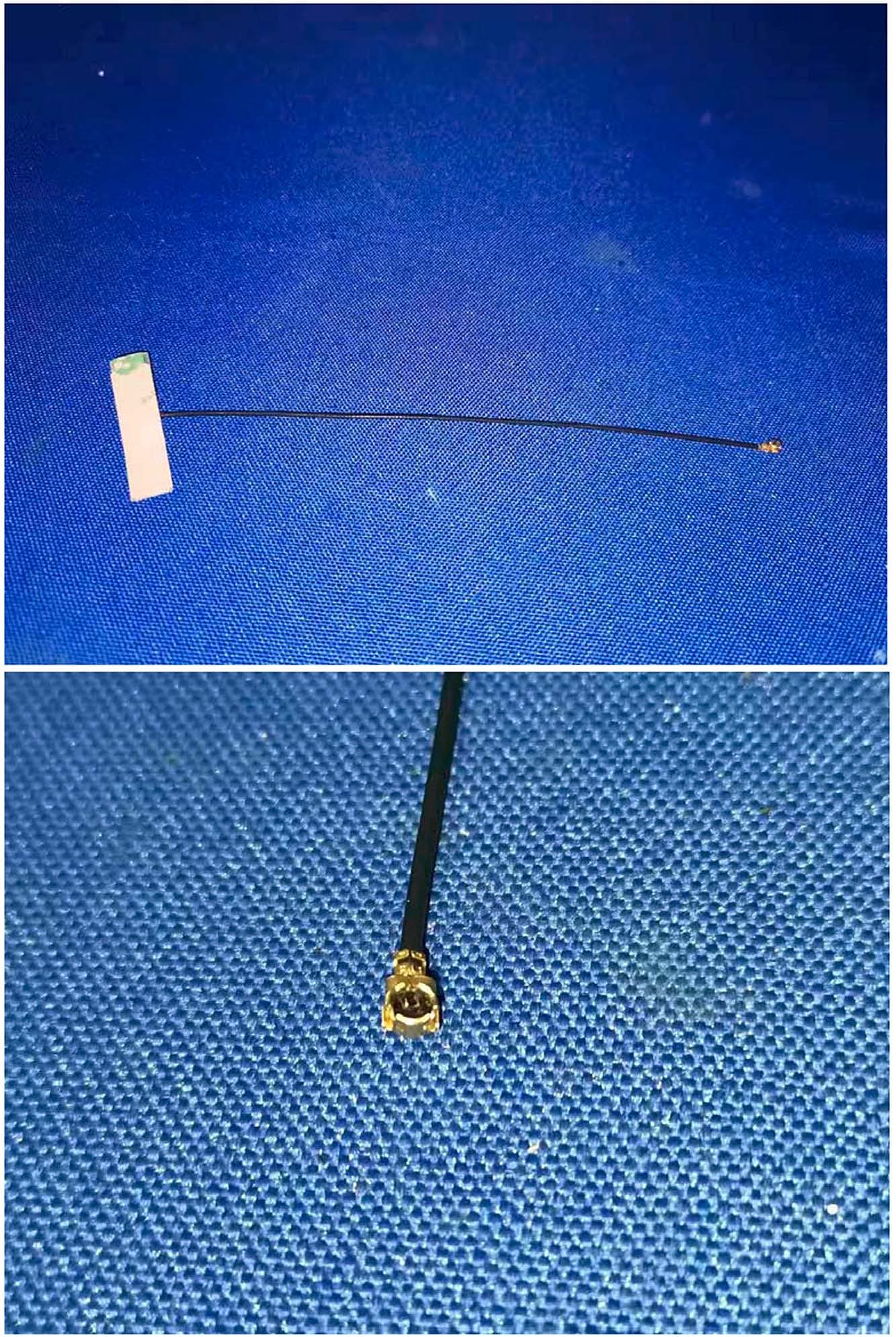
Click to zoom
Application Details
- Equipment Class
- DTS - Digital Transmission System
- Date of Grant
- May 14, 2021
- Application Purpose
- Original Equipment
- Date of Application
- May 13, 2021
- Equipment Note
- ZBEE3
- Frequency Range
- 2405.00000000 - 2480.00000000
- Country
- China
Documents & Files
Document Text
Text extracted from the exhibit documents filed with the FCC. Open a document above to read the original.
Users Manual
Hangzhou Grom Technology Co.,Ltd. ZigBee Module Datasheet ZBee3 COPYRIGHT INFO The information contained in this document is the proprietary information of Hangzhou Grom Technology Co.,Ltd. (hereinafter referred as Grom). The contents are confidential and any disclosure to persons other than the officers, employees, agents or subcontractors of the owner or licensee of this document, without the prior written consent of Grom, is strictly prohibited. Further, no portion of this document may be reproduced, stored in a retrieval system, or transmitted in any form or by any means, electronic or mechanical, including photocopying and recording, without the prior written consent of Grom, the copyright holder. Grom publishes this document without making any warranty as to the content contained herein. Further Grom reserves the right to make modifications, additions and deletions to this document due to typographical errors, inaccurate information, or improvements to products mentioned in the document at any time and without notice. Such changes will, nevertheless be incorporated into new editions of this document. VERSION HISTORY V1.0.0 2019/08/04 1st issue of preliminary document Hangzhou Grom Technology Co.,Ltd. Add: Room800,Building3#,Longtan Rd 16#,Cangqian street, Hangzhou City, China. 311121 Website:www.gromiot.com 1 Content 1. Introduction ................................................................................................................... 2 1.1. Summary ............................................................................................................. 2 1.2. Applications ......................................................................................................... 2 1.3. Key Features ....................................................................................................... 2 1.4. Advantage ........................................................................................................... 3 1.5. Abbreviations and Acronyms ............................................................................... 3 1.6. Related Documents ............................................................................................ 4 2. Specifications ................................................................................................................ 5 2.1. Electrical Characteristics ..................................................................................... 5 2.1.1. Absolute Maximum Ratings ...................................................................... 5 2.1.2. Test Conditions ......................................................................................... 5 2.1.3. RF Characteristics .................................................................................... 5 2.1.4. Microcontroller Characteristics .................................................................. 6 2.1.5. Module Interfaces characteristics ............................................................. 6 2.2. Physical/Environmental Characteristics .............................................................. 6 2.3. Pin Configuration ................................................................................................ 6 2.4. Antenna Specifications ........................................................................................ 9 3. Ordering Information ................................................................................................... 10 4. Contact Us .................................................................................................................. 10 Hangzhou Grom Technology Co.,Ltd. Add: Room800,Building3#,Longtan Rd 16#,Cangqian street, Hangzhou City, China. 311121 Website:www.gromiot.com 2 1. Introduction 1.1. Summary ZBee3 is an ultra-compact, low-power, high-sensitivity 2.4 GHz IEEE 802.15.4/ ZigBee module, which can be used for wireless sensing, control and data acquisition applications. 1.2. Applications ZBee3 module is compatible with IEEE 802.15.4/ ZigBee stack that supports a self-healing, self-organizing mesh network, while optimizing network traffic and minimizing power consumption. The applications include but not limited to: Building automation & monitoring Environmental monitoring Security Industrial monitoring Automated meter reading (AMR) 1.3. Key Features Size: 19.3 x 13.6 x 3.0mm Output power: MAX 20dBm High RX sensitivity : -102dBm Outperforming link budget : 122dB Communication distance : SMA antenna: 800~1000m (Visual distance); Ceramic antenna:200~300m (Visual distance) Low power consumption Sleep mode : <5.0μA RX mode: [email protected] GHz (250 kbps O-QPSK DSSS) TX mode: 33.8mA@10dBm;185mA@20dBm Ample memory resources: Flash: 1024K bytes;RAM: 96K bytes Hangzhou Grom Technology Co.,Ltd. Add: Room800,Building3#,Longtan Rd 16#,Cangqian street, Hangzhou City, China. 311121 Website:www.gromiot.com 3 Wide range of interfaces (both analog and digital): 20 x GPIO 12-bit 1 Msps SAR ADC 3 x USART transceiver 2 x I 2 C IEEE 802.15.4 compliant transceiver Optional antenna reference designs 1.4. Advantage Small package for small devices Leading link budget 4 PCB board, good ESD/EMC protection ability. Ample memory for software application Mesh networking capability ISM worldwide license-free operation 1.5. Abbreviations and Acronyms ADC Analog-to -Digital Converter API Application Programming Interface DC Direct Current DTR Data Terminal Ready DIP Duap In-line package EEPROM Electrically Erasable Programmable Read-Only Memory ESD Electrostatic Discharge GPIO General Purpose Input/Output HAL Hardware Abstraction Layer HVAC Heating, Ventilating and Air Conditioning HW Hardware TWI Inter-Integrated Circuit IEEE Institute of Electrical and Electrionics Engineers IRQ Interrupt Request ISM Industrial, Scientific and Medical radio band JTAG Digital interface for debugging of embedded device, also known as IEEE 1149.1 standard inter…
Text truncated - open the document above for the full version.
Attestation Statements
Declaration letter We Hangzhou Grom Technology Co.,Ltd. Hereby Declare that The product ZBEE3 models no. ZBEE3S2F8C, ZBEE3S2F8U are all identical in interior structure, electrical circuits and components, and only the antenna is different. ZBEE3S2F8C uses Chip antenna while ZBEE3S2F8U uses UFL antenna When using Chip antenna, R3 and C16 NC (not connection); When using UFL antenna, R4 and C15 NC (not connection); Your assistance on this matter is highly appreciated. Date: May 11, 2021 <Signature>: Name:Terry Tong Title:CEO Applicant Company:Hangzhou Grom Technology Co., Ltd.
Cover Letter(s)
May 11, 2021 Equipment Autorisation Division Federal Communications Commission 7435 Oakland Mills Road Columbia, MD 21046 FCC ID: 2AZEG-ZBEE3S2F8C Product Name: ZBEE3 Request for Confidentiality Pursuant to Sections 0.457 and 0.459 of the commissions rules, we hereby request that the following documents be held confidential: • Schematics • Block diagram • Operation description These materials contain trade secrets and proprietary information and are not customarily released to the public. The public disclosure of this information might be harmful to the company and provide unjustified benefits to our competitors. <Signature>: Name:Terry Tong Title:CEO Applicant Company:Hangzhou Grom Technology Co., Ltd.
Cover Letter(s)
May 11, 2021 Federal Communications Commission Authorization & Evaluation Division 7345 Oakland Mills Road Columbia, Maryland 21046 Authority to Act as Agent On our behalf, I appoint Shenzhen Timeway Testing Laboratories/ Zone C, 1st Floor, Zone C, 1st Floor, Block B, Jun Xiang Da Building, Zhongshan Park Road West, Tong Le Village, Nanshan District, Shenzhen, China (Name of Agent company name and address) to act as our agent in the preparation of this application for equipment certification. I certify that submitted documents properly describe the device or system for which equipment certification is sought. I also certify that each unit manufactured, imported or marketed, as defined in the Federal Communications Commission’s regulations will have affixed to it a label identical to that submitted for approval with this application. For instances where our authorized agent signs the application for certification on our behalf, I acknowledge that all responsibility for complying with the terms and conditions for certification, still resides with Hangzhou Grom Technology Co., Ltd. / Room815-2, Building3#, Longtan Rd 16#, Cangqian street, Yuhang District, Hangzhou, China <Signature>: Name:Terry Tong Title:CEO Applicant Company:Hangzhou Grom Technology Co., Ltd.
Cover Letter(s)
Modular approval Declaration letter We ,Hangzhou Grom Technology Co., Ltd. apply Single modular approval for Product Name: ZBEE3 Model: ZBEE3S2F8C, ZBEE3S2F8U FCC ID: 2AZEG-ZBEE3S2F8C According to 996369 D01 Module E quip Auth Guide v01r04 and 15.212 requirement: 1)The radio elements must have the radio frequency circuitry shielded. P hysical components and tuning capacitor(s) may be located external to the shield, but must be on the module assembly; Answer :Yes, shielding for both side. 2)The module must have buffered modulation/data inputs to ensure that the dev ice will comply with Part 15 requirements with any type of input signal; Answer : Yes ;All inputs to the modules are buffered through logic or microprocessor inputs. 3)The modular transmitter must have its own power supply regulation. Answer :Yes ;A low drop out regulator is used for modular power supply regulation. 4)The module must contain a per manently attached antenna, or contain a unique antenna connector, and be marketed and operated only with specific antenna(s), per Sections15.203, 15.204(b), 15.204(c), 15.212(a), 2.929(b); Answer : Yes ;Device is equipped with a chip antenna or a integral antenna with SMA antenna connector. (5)The module must demonstrate compliance in a stand-alone configuration; Answer : Yes,distance between modular and all AEs are bigger than 10cm , refer to setup photo. (6)The module must be labeled with its permanently affixed FCC ID label, or use an electronic display (See KDB Publication 784748 about labeling requirements); Answer :Yes ;The modular has a permanent fixed label, and below statement was listed in the User Manual; The host device must be labeled to display the FCC ID of the module “Contains FCC ID: 2AZEG-ZBEE3S2F8C” (7)The module must comply with all specific rules applicable to the transmitter including all the conditions provided in the integration instructions by the grantee; Answer : Yes ;The module comply with all specific rules applicable to the transmitter including all the conditions provided in the integration instructions by the grantee, Refer to test report and user manual. (8) The module must comply with RF exposure requirements Answer :Yes ;Transmitter meets MPE calculation of 47 CFR 1.1307. Refer to MPE Reports and Refer to modular installation manual Please contact me if you have any further questions. Thanks for your attention. Best Regards, <Signature> : Name:Terry Tong Title:CEO Applicant Company :Hangzhou Grom Technology Co., Ltd.
External Photos
Chip Antenna UFL antenna:
ID Label/Location Info
ZBee3 FCC ID:2AZEG-ZBEE3S2F8C
ID Label/Location Info
Label Location
RF Exposure Info
Maximum Permissible Exposure FCC ID: 2AZEG-ZBEE3S2F8C Applicable Standard Systems operating under the provisions of this section shall be operated in a manner that ensures that the public is not exposed to radio frequency energy level in excess limit for maximum permissible exposure. In accordance with 47 CFR FCC Part 2 Subpart J, section 2.1091 this device has been defined as a mobile device whereby a distance of 0.2m normally can be maintained between the user and the device. (a) Limits for Occupational / Controlled Exposure Frequency Range (MHz) Electric Field Strength (E) (V/m) Magnetic Field Strength (H) (A/m) Power Density (S) (mW/cm 2 ) Averaging Times ︱E︱ 2 , ︱H︱ 2 or S (minutes) 0.3-3.0 614 1.63 (100)* 6 3.0-30 1842/f 4.89/f (900/f)* 6 30-300 61.4 0.163 1.0 6 300-1500 F/300 6 1500-100000 5 6 (b) Limits for General Population / Uncontrolled Exposure Frequency Range (MHz) Electric Field Strength (E) (V/m) Magnetic Field Strength (H) (A/m) Power Density (S) (mW/cm 2 ) Averaging Times ︱E︱ 2 , ︱H︱ 2 or S (minutes) 0.3-1.34 614 1.63 (100)* 30 1.34-30 824/f 2.19/f (180/f)* 30 30-300 27.5 0.073 0.2 30 300-1500 F/1500 30 1500-100000 1.0 30 Note: f=frequency in MHz; *Plane-wave equivalent power density MPE Calculation Method E (V/m) = (30*P*G) 0.5 /d Power Density: Pd (W/m 2 ) = E 2 /377 E = Electric Field (V/m) P = Peak RF output Power (W) G = EUT Antenna numeric gain (numeric) d = Separation distance between radiator and human body (m) The formula can be changed to Pd = (30*P*G) / (377*d 2 ) From the peak EUT RF output power, the minimum mobile separation distance, d=0.2m, as well as the gain of the used antenna, the RF power density can be obtained. Calculated Result and Limit Antenna Gain: 2.0dBi Antenna Gain (Numeric) Output Power (dBm) Peak Output Power (mW) Power Density (S) (mW/cm 2 ) Limit of Power Density (S) (mW/cm 2 ) Test Result 1.585 17.90 61.66 0.02 1 Compiles Note: the worse case was recorded.
Test Report
Report No.: TW2103039E File reference No.: 2021-04-25 Applicant: Hangzhou Grom Technology Co.,Ltd. Product: ZBEE3 Model No.: ZBEE3S2F8C, ZBEE3S2F8U Trademark: N/A Te st Standards: FCC Part 15.247 Test result: It is herewith confirmed and found to comply with the requirements set up by ANSI C63.10, FCC Part 15.247 for the evaluation of electromagnetic compatibility Approved By Jack Chung Manager Dated: April 25, 2021 Results appearing herein r elate only to the sample tested The technical reports is issued errors and omissions exempt and is subject to withdrawal at SHENZHEN TIMEWAY TESTING LABORATORIES Zone C, 1st Floor, Block B, J un Xiang Da Building, Zhongshan Park Road West, Tong Le Village, Nanshan District, Shenzhen, China Tel (755) 83448688, Fax (755) 83442996, E-Mail:[email protected] Report No.: TW2103039E Page 2 of 60 Date: 2021-04-25 The report refers only to the sample tested and does not apply to the bulk. This report is issued in confidence to the client and it will be strictly treated as such by the SHENZHEN TIMEWAY TESTING LABORATORIES. It may not be reproduced rather in its entirety or in part and it may not be used for adverting. The client to whom the report is issued may, however, show or send it . or a certified copy there of prepared by the SHENZHEN TIMEWAY TESTING LABORATORIES. to his customer. Supplier or others persons directly concerned. SHENZHEN TIMEWAY TESTING LABORATORIES. will not, without the consent of the client enter into any discussion of correspondence with any third party concerning the contents of the report. In the event of the improper use of the report. The SHENZHEN TIMEWAY TESTING LABORATORIES. reserves the rights to withdraw it and to adopt any other remedies which may be appropriate. Special Statement: The testing quality ability of our laboratory meet with “Quality Law of People’s Republic of China” Clause 19. The testing quality system of our laboratory meet with ISO/IEC-17025 requirements, which is approved by CNAL. This approval result is accepted by MRA of APLAC. Our test facility is recognized, certified, or accredited by the following organizations: CNAL-LAB Code: L2292 The EMC Laboratory has been assessed and in compliance with CNAL/AC01:2002 accreditation criteria for testing Laboratories (identical to ISO/IEC 17025:2005 General Requirements) for the Competence of testing Laboratories. FCC-Registration No.: 744189 The EMC Laboratory has been registered and fully described in a report filed with the (FCC) Federal Communications commission. The acceptance letter from the FCC is maintained in our files. Registration No.: 744189. Industry Canada (IC) —Registration No.:5205A The EMC Laboratory has been registered by Certification and Engineering Bureau of Industry Canada for radio equipment testing with Registration No.: 5205A. A2LA (Certification Number:5013.01) The EMC Laboratory has been accredited by the American Association for Laboratory Accreditation (A2LA). Certification Number:5013.01 Report No.: TW2103039E Page 3 of 60 Date: 2021-04-25 The report refers only to the sample tested and does not apply to the bulk. This report is issued in confidence to the client and it will be strictly treated as such by the SHENZHEN TIMEWAY TESTING LABORATORIES. It may not be reproduced rather in its entirety or in part and it may not be used for adverting. The client to whom the report is issued may, however, show or send it . or a certified copy there of prepared by the SHENZHEN TIMEWAY TESTING LABORATORIES. to his customer. Supplier or others persons directly concerned. SHENZHEN TIMEWAY TESTING LABORATORIES. will not, without the consent of the client enter into any discussion of correspondence with any third party concerning the contents of the report. In the event of the improper use of the report. The SHENZHEN TIMEWAY TESTING LABORATORIES. reserves the rights to withdraw it and to adopt any other remedies which may be appropriate. Test Report Conclusion Content 1.0 General Details ................................................................................................ 4 1.1 Test Lab Details................................................................................................ 4 1.2 Applicant Details.............................................................................................. 4 1.3 Description of EUT ........................................................................................... 4 1.4 Submitted Sample.............................................................................................. 5 1.5 Test Duration................................................................................................... 5 1.6 Test Uncertainty............................................................................................... 5 1.7 Test By.......................................................................................................... 5 2.0 List of Measurement Equipment......................................................................... 6 3.0 Technical Details............................................................................................. 7 3.1 Summary of Test Results..................................................................................... 7 3.2 Test Standards.................................................................................................. 7 4.0 EUT Modification............................................................................................. 7 5.0 Power Line Conducted Emission Test...................................................................... 8 5.1 Schematics of the Test........................................................................................ 8 5.2 Test Method and Test Procedure............................................................................ 8 5.3 Configuration of the EUT.................................................................................... 8 5.4 EUT Operating Condition.............…
Text truncated - open the document above for the full version.
Test Setup Photos
Conducted Emission Test Setup: Radiated Emission Test Setup:
Contact Information
Applicant
Terry Tong(CEO)
Test Firm
Shenzhen Timeway Testing LaboratoriesTerry Tang
[email protected]+86-755-83448688
Technical Specifications
| # | Rule Parts | Frequency Range | Power Output |
|---|---|---|---|
| 1 | 15C | 2.40 GHz - 2.48 GHz | 61.66 mW |