2AZELADCP1P0BSCardio Pulmonary Management system
Analog Devices, Inc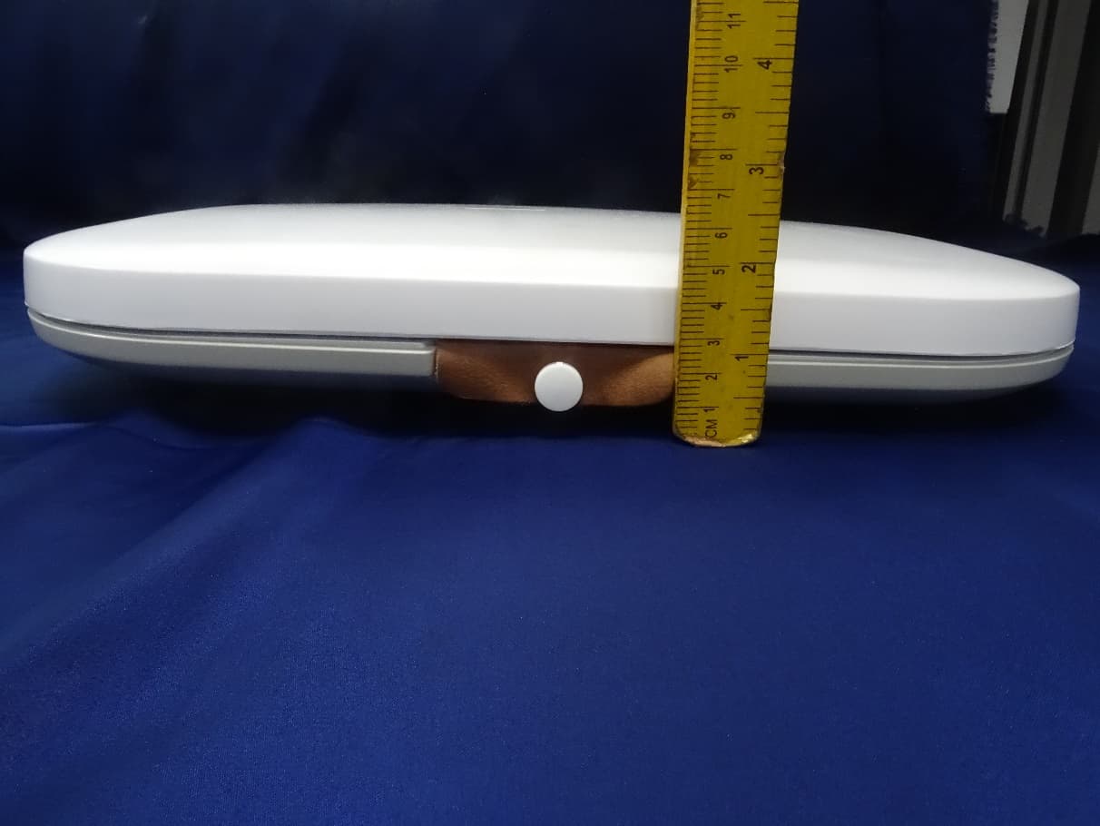
Click to zoom
Application Details
- Equipment Class
- PCB - PCS Licensed Transmitter
- Date of Grant
- Apr 27, 2021
- Application Purpose
- Original Equipment
- Date of Application
- Apr 07, 2021
- Equipment Note
- Cardio Pulmonary Management system
- Frequency Range
- 814.00000000 - 824.00000000
- Company
- Analog Devices, Inc
- Country
- United States
Documents & Files
Document Text
Text extracted from the exhibit documents filed with the FCC. Open a document above to read the original.
Users Manual
1 Version C DOC #: CFU0001 Revision C – March 2021 For assistance operating the CPM System, please contact Analog Devices: One Technology Way PO Box 9106 Norwood, MA 02062 USA (781) 329-4700 (800) 262-5643 DISCLAIMER: Information, operation, specifications, and product appearance may change without notice. SYMBOLS GLOSSARY: The symbols glossary is located at the end of this Instructions for Use guide READ ENTIRE INSTRUCTIONS FOR USE BEFORE OPERATING THE ADI CPM SYSTEM ADI CARDIOPULMONARY MANAGEMENT (CPM) SYSTEM Clinician Instructions for Use – Device and Mobile Application 2 Version C Clinician Instructions for Use – Device and Mobile Application C Contents Glossary & Acronyms ................................................................................................................................................................ 4 Part 1. General System Information ................................................................................................................................. 6 1. Introduction ........................................................................................................................................................................ 6 2. Indications and Contraindications for Use ............................................................................................................... 6 3. Warnings and Precautions ................................................................................................................................................ 7 3.1 General ...............................................................................................................................................................7 3.2 Implant Information ...........................................................................................................................................9 3.3 Blood Thinner and Steroid Precautions ..............................................................................................................9 4. Detailed Description of the System ................................................................................................................................. 10 4.1 System Components ......................................................................................................................................... 10 CPM Device ............................................................................................................................................................. 10 Adhesive Disposables .............................................................................................................................................. 11 Alignment Tool ........................................................................................................................................................ 11 Base Station ............................................................................................................................................................. 12 Mobile Application .................................................................................................................................................. 12 Cloud Software ........................................................................................................................................................ 13 4.2 How the System Works ..................................................................................................................................... 13 4.3 Measurement Parameters ................................................................................................................................ 13 4.4 Parameter Thresholds ...................................................................................................................................... 16 4.5 Device Use and Duration .................................................................................................................................. 17 4.6 Device Placement and Location ........................................................................................................................ 17 Guidance for Correct Clinician Placement............................................................................................................... 18 Incorrect CPM Device Placements .......................................................................................................................... 20 Part 2. In-Clinic Instructions For Use .............................................................................................................................. 22 5. Getting Started ........................................................................................................................................................ 22 6. Baseline Measurement Preparation and Device Setup ................................................................................................... 22 6.1 Before meeting your patient for the baseline reading ..................................................................................... 22 6.2 Preparing the skin ............................................................................................................................................. 23 6.3 Fitting and sizing the CPM Device ..................................................................................................................... 23 6.4 Pairing the CPM Device to the Mobile App ...................................................................................................... 25 7. In-Clinic Setup and Baseline ................................................................................................................................... 26 7.1 Taking a Baseline Reading using the CPM Mobile App ..................................................................................... 27 3 Version C Clinician Instructions for Use – Device and Mobil…
Text truncated - open the document above for the full version.
Users Manual
1 Version C DOC #: CFU0001 Revision C – March 2021 For assistance operating the CPM System, please contact Analog Devices: One Technology Way PO Box 9106 Norwood, MA 02062 USA (781) 329-4700 (800) 262-5643 DISCLAIMER: Information, operation, specifications, and product appearance may change without notice. SYMBOLS GLOSSARY: The symbols glossary is located at the end of this Instructions for Use guide READ ENTIRE INSTRUCTIONS FOR USE BEFORE OPERATING THE ADI CPM SYSTEM ADI CARDIOPULMONARY MANAGEMENT (CPM) SYSTEM Clinician Instructions for Use – Device and Mobile Application 2 Version C Clinician Instructions for Use – Device and Mobile Application C Contents Glossary & Acronyms ................................................................................................................................................................ 4 Part 1. General System Information ................................................................................................................................. 6 1. Introduction ........................................................................................................................................................................ 6 2. Indications and Contraindications for Use ............................................................................................................... 6 3. Warnings and Precautions ................................................................................................................................................ 7 3.1 General ...............................................................................................................................................................7 3.2 Implant Information ...........................................................................................................................................9 3.3 Blood Thinner and Steroid Precautions ..............................................................................................................9 4. Detailed Description of the System ................................................................................................................................. 10 4.1 System Components ......................................................................................................................................... 10 CPM Device ............................................................................................................................................................. 10 Adhesive Disposables .............................................................................................................................................. 11 Alignment Tool ........................................................................................................................................................ 11 Base Station ............................................................................................................................................................. 12 Mobile Application .................................................................................................................................................. 12 Cloud Software ........................................................................................................................................................ 13 4.2 How the System Works ..................................................................................................................................... 13 4.3 Measurement Parameters ................................................................................................................................ 13 4.4 Parameter Thresholds ...................................................................................................................................... 16 4.5 Device Use and Duration .................................................................................................................................. 17 4.6 Device Placement and Location ........................................................................................................................ 17 Guidance for Correct Clinician Placement............................................................................................................... 18 Incorrect CPM Device Placements .......................................................................................................................... 20 Part 2. In-Clinic Instructions For Use .............................................................................................................................. 22 5. Getting Started ........................................................................................................................................................ 22 6. Baseline Measurement Preparation and Device Setup ................................................................................................... 22 6.1 Before meeting your patient for the baseline reading ..................................................................................... 22 6.2 Preparing the skin ............................................................................................................................................. 23 6.3 Fitting and sizing the CPM Device ..................................................................................................................... 23 6.4 Pairing the CPM Device to the Mobile App ...................................................................................................... 25 7. In-Clinic Setup and Baseline ................................................................................................................................... 26 7.1 Taking a Baseline Reading using the CPM Mobile App ..................................................................................... 27 3 Version C Clinician Instructions for Use – Device and Mobil…
Text truncated - open the document above for the full version.
Cover Letter(s)
Analog Devices, Inc. | One Technology Way | P.O. Box 9106 | Norwood, MA 02062-9106 | U.S.A | Tel: 781.329.4700 Date: April 7 2021 Federal Communications Commission Authorization and Evaluation division Subject: CPM Base station NB-IOT operation (FCC ID: 2AZELADCP1P0BS) The CPM Base station uses LTE-M protocol as a mode of communication with a 2G Backup. NB-IOT is not used in this device. Sincerely, Arvind K. Venkatesh Analog Devices Inc System Designer Medical Products MS625 804 Woburn Street Wilmington Massachusetts - 01887-3462 [email protected] 781-937-1879
Cover Letter(s)
Justification for Re-use of radio test results We, Analog Devices Incorporated, believe the conducted signal test data on original reports provided by Sierra Wireless Inc. (Single Module,FCC ID: N7NWP77B) can be re-used for the following reasons: 1. Applicant has built in the radio module according to the specific radio module integration guides. 2. The applicant has not modified either hardware or software provided by the module manufacturer. Test item Rule Part Report No. Justification of re-use LTE, GSM Part 22H, Part 24E, Part 27 & Part 90 FG7D054A,FG7D054B, FG7D054C See above Arvind K. Venkatesh Ph.D. 3/30/2021 System Designer Medical Products Analog Devices 804 Woburn Street Wilmington Massachusetts - 01887-3462
External Photos
Produkte Products www.tuv.com EUT External Photos Reference Test Report No: ULR-TC568821300000017F Seite 1 von 3 Page 1 of 3 EUT External Photos EUT Top view EUT Rear View Produkte Products www.tuv.com EUT External Photos Reference Test Report No: ULR-TC568821300000017F Seite 2 von 3 Page 2 of 3 EUT Dimensional View EUT Dimensional View Produkte Products www.tuv.com EUT External Photos Reference Test Report No: ULR-TC568821300000017F Seite 3 von 3 Page 3 of 3 EUT Dimensional View
ID Label/Location Info
FCC ID: 2AZELADCP1P0BS
ID Label/Location Info
FCC ID: 2AZELADCP1P0BS
Internal Photos
Produkte Products www.tuv.com EUT Internal Photos Reference Test Report No: ULR-TC568821300000017F Seite 1 von 3 Page 1 of 3 EUT Internal Photos Internal View PCB TOP View Produkte Products www.tuv.com EUT Internal Photos Reference Test Report No: ULR-TC568821300000017F Seite 2 von 3 Page 2 of 3 PCB Rear View PCB Dimensional View Produkte Products www.tuv.com EUT Internal Photos Reference Test Report No: ULR-TC568821300000017F Seite 3 von 3 Page 3 of 3 PCB Dimensional View
RF Exposure Info
Produkte Products www.tuv.com RF Exposure Reference Test Report No: ULR-TC568821300000017F Seite 1 von 2 Page 1 of 2 1 RF Exposure Report 1.1 RF Exposure Measurement The limit for Maximum Permissible Exposure (MPE) specified in FCC 1.1310 is followed. The gain of the antennas used in the product is extracted from the Antenna data sheets provided and also the maximum total power input to the antenna is measured. Through the Friis transmission formula and the maximum gain of the antenna, we can calculate the distance, away from the product, where the limit of MPE is reached. Although the Friis Transmission formula is far field assumption, the calculated result of that is an over-prediction for near field power density. It is taken as worst case to specify the safety range. 1.2 RF Exposure Limit According to FCC 1.1310: The criteria listed in the following table shall be used to evaluate the environmental impact of the human exposure to radio-frequency (RF) radiation as specified in 1.1307 (b) showed in Table 1. F or ƒ = Frequency in MHz Produkte Products www.tuv.com RF Exposure Reference Test Report No: ULR-TC568821300000017F Seite 2 von 2 Page 2 of 2 1.2.1 Friss Formula Friss Transmission Formula: Pd = (Pout * G) / (4*pi*r²) Where Pd = power density in mW/cm² Pout = output power to antenna in mW G = gain of antenna in linear scale Pi = 3.1416 R = Distance between observation point and the center of radiator in cm If we know the maximum gain of the antenna and the total output power to the antenna, through calculation, we will know MPE value at distance 20cm. 1.2.2 Classification The antenna of this product, under normal use condition, is at least 20cm away from the body of the user. Warning statement to the user for keeping at least 20cm or more separation distance from the antenna should be included in the User manual. Note: ± 1 dB tune up value is considered for MPE calculation. Protocol: LTE & GSM Test Results Manufacturer has declared the tune-up value as ±1 dB is considered in MPE calculation. Antenna type: Wide Band Antenna(2dBi for above 1GHz Bands, -1.95dBi for below 1GHz Bands) Cellular protocol Band Cell Bandwidth (MHz) Measured Frequency (MHz) Maximum measured RF output power at antenna terminal (dBm) Tune-up tolerance (dB) Antenn a Gain in Linear Scale Power Density (mW/cm²) Limit (mW/cm²) LTE 2 10 1855 23.21 1 1.5849 0.0831 1.0 4 10 1750 22.92 1 1.5849 0.0778 1.0 12 10 711 23.88 1 0.6382 0.0391 0.474 13 5 799.5 22.96 1 0.6382 0.0316 0.533 26 10 844 23.98 1 0.6382 0.0400 0.563 Cellular protocol Band Measured Frequency (MHz) Maximum measured RF output power at antenna terminal (dBm) Tune-up tolerance (dB) Antenna Gain in Linear Scale Power Density (mW/cm²) Limit (mW/cm²) GSM 850 824.2 32.46 1 0.6382 0.3548 0.549 1900 1850.2 30.31 1 1.5849 0.33863 1.0
Test Report
SPORTON INTERNATIONAL INC. Page Number : 1 of 19 TEL : 886-3-327-3456 Report Issued Date : Apr. 24, 2018 FAX : 886-3-328-4978 Report Version : Rev. 01 FCC ID : N7NWP77B Report Template No.: BU5-FG22/24/27 Version 2.0 FCC RF Test Report Report No. : FG7D0540A FCC RF Test Report CUSTOMER : Sierra Wireless Inc. EQUIPMENT : Radio Module MODEL NAME : WP7702 FCC ID : N7NWP77B STANDARD : FCC 47 CFR Part 2, 22(H), 24(E) CLASSIFICATION : PCS Licensed Transmitter (PCB) This is a partial report. The product was received on Dec. 05, 2017 and testing was completed on Dec. 19, 2017. We, SPORTON INTERNATIONAL INC., would like to declare that the tested sample has been evaluated in accordance with the test procedures given in ANSI / TIA-603-E and has been in compliance with the applicable technical standards. The test results in this report apply exclusively to the tested model / sample. Without written approval of SPORTON INTERNATIONAL INC., the test report shall not be reproduced except in full. Reviewed by: Joseph Lin / Supervisor Approved by: Jones Tsai / Manager SPORTON INTERNATIONAL INC. No. 52, Hwa Ya 1 st Rd., Hwa Ya Technology Park, Kwei-Shan District, Tao Yuan City, Taiwan, R.O.C. SPORTON INTERNATIONAL INC. Page Number : 2 of 19 TEL : 886-3-327-3456 Report Issued Date : Apr. 24, 2018 FAX : 886-3-328-4978 Report Version : Rev. 01 FCC ID : N7NWP77B Report Template No.: BU5-FG22/24/27 Version 2.0 FCC RF Test Report Report No. : FG7D0540A TABLE OF CONTENTS REVISION HISTORY .......................................................................................................................................... 3 SUMMARY OF TEST RESULT ......................................................................................................................... 4 1 GENERAL DESCRIPTION .......................................................................................................................... 5 1.1 Customer ........................................................................................................................................... 5 1.2 Manufacturer ..................................................................................................................................... 5 1.3 Product Feature of Equipment Under Test ....................................................................................... 5 1.4 Product Specification of Equipment Under Test ............................................................................... 5 1.5 Modification of EUT ........................................................................................................................... 5 1.6 Testing Location ................................................................................................................................ 6 1.7 Applicable Standards ........................................................................................................................ 6 2 TEST CONFIGURATION OF EQUIPMENT UNDER TEST ........................................................................ 7 2.1 Test Mode.......................................................................................................................................... 7 2.2 Connection Diagram of Test System ................................................................................................ 7 2.3 Support Unit used in test configuration ............................................................................................. 8 2.4 Measurement Results Explanation Example .................................................................................... 8 2.5 Frequency List of Low/Middle/High Channels ................................................................................... 8 3 CONDUCTED TEST RESULT ..................................................................................................................... 9 3.1 Measuring Instruments ...................................................................................................................... 9 3.2 Test Setup ......................................................................................................................................... 9 3.3 Test Result of Conducted Test .......................................................................................................... 9 3.4 Conducted Output Power ................................................................................................................ 10 3.5 Peak-to-Average Ratio .................................................................................................................... 11 3.6 99% Occupied Bandwidth and 26dB Bandwidth Measurement...................................................... 12 3.7 Conducted Band Edge .................................................................................................................... 13 3.8 Conducted Spurious Emission ........................................................................................................ 14 3.9 Frequency Stability .......................................................................................................................... 15 4 RADIATED TEST ITEMS .......................................................................................................................... 16 4.1 Measuring Instruments .................................................................................................................... 16 4.2 Test Setup ....................................................................................................................................... 16 4.3 Test Result of Radiated Test ........................................................................................................... 16 4.4 Field Strength of Spurious Radiation Measurement ....................................................................... 17 5 LIST OF MEASURING EQUIPMENT .............................................................…
Text truncated - open the document above for the full version.
Test Report
SPORTON INTERNATIONAL INC. Page Number : 1 of 23 TEL : 886-3-327-3456 Report Issued Date : Apr. 24, 2018 FAX : 886-3-328-4978 Report Version : Rev. 01 FCC ID : N7NWP77B Report Template No.: BU5-FGLTE Version 2.0 FCC RF Test Report Report No. : FG7D0540B FCC LTE M1 Test Report CUSTOMER : Sierra Wireless Inc. EQUIPMENT : Radio Module MODEL NAME : WP7702 FCC ID : N7NWP77B STANDARD : 47 CFR Part 2, 22(H), 24(E), 27 CLASSIFICATION : PCS Licensed Transmitter (PCB) This is a partial report. The product was received on Dec. 05, 2017 and completely tested on Jan. 11, 2018. We, SPORTON INTERNATIONAL INC., would like to declare that the tested sample has been evaluated in accordance with the test procedures given in ANSI / TIA-603-E and the testing has shown the tested sample to be in compliance with the applicable technical standards. The test results in this report apply exclusively to the tested model / sample. Without written approval of SPORTON INTERNATIONAL INC., the test report shall not be reproduced except in full. Reviewed by: Joseph Lin / Supervisor Approved by: Jones Tsai / Manager SPORTON INTERNATIONAL INC. No. 52, Hwa Ya 1 st Rd., Hwa Ya Technology Park, Kwei-Shan District, Tao Yuan City, Taiwan, R.O.C. SPORTON INTERNATIONAL INC. Page Number : 2 of 23 TEL : 886-3-327-3456 Report Issued Date : Apr. 24, 2018 FAX : 886-3-328-4978 Report Version : Rev. 01 FCC ID : N7NWP77B Report Template No.: BU5-FGLTE Version 2.0 FCC RF Test Report Report No. : FG7D0540B TABLE OF CONTENTS REVISION HISTORY .......................................................................................................................................... 3 SUMMARY OF TEST RESULT ......................................................................................................................... 4 1 GENERAL DESCRIPTION .......................................................................................................................... 5 1.1 Customer ........................................................................................................................................... 5 1.2 Manufacturer ...................................................................................................................................... 5 1.3 Product Feature of Equipment Under Test ........................................................................................ 5 1.4 Product Specification of Equipment Under Test ................................................................................ 5 1.5 Modification of EUT ........................................................................................................................... 5 1.6 Testing Location ................................................................................................................................ 6 1.7 Applicable Standards ......................................................................................................................... 6 2 TEST CONFIGURATION OF EQUIPMENT UNDER TEST ........................................................................ 7 2.1 Test Mode .......................................................................................................................................... 7 2.2 Connection Diagram of Test System ................................................................................................. 8 2.3 Support Unit used in test configuration and system .......................................................................... 9 2.4 Measurement Results Explanation Example ..................................................................................... 9 2.5 Frequency List of Low/Middle/High Channels ................................................................................. 10 3 CONDUCTED TEST ITEMS ...................................................................................................................... 12 3.1 Measuring Instruments .................................................................................................................... 12 3.2 Test Setup ....................................................................................................................................... 12 3.3 Conducted Output Power ................................................................................................................ 13 3.4 Peak-to-Average Ratio .................................................................................................................... 14 3.5 Occupied Bandwidth ........................................................................................................................ 15 3.6 Conducted Band Edge .................................................................................................................... 16 3.7 Conducted Spurious Emission ........................................................................................................ 18 3.8 Frequency Stability .......................................................................................................................... 19 4 RADIATED TEST ITEMS .......................................................................................................................... 20 4.1 Measuring Instruments .................................................................................................................... 20 4.2 Test Setup ....................................................................................................................................... 20 4.3 Test Result of Radiated Test ........................................................................................................... 20 4.4 Radiated Spurious Emission ........................................................................................................... 21 5 LIST OF MEASURING EQUIPMENT ........................................................................................................ 22 6 UNCERTAINTY OF EVALUATIO…
Text truncated - open the document above for the full version.
Test Report
Report No. : FG7D0540B LMH 101000722.5122.8622.58 101500722.4922.8522.56 106000721.5621.4221.63 101000723.1022.6523.25 101500723.0922.6223.23 106000721.3721.5522.30 51000322.6322.8922.73 51500322.3922.6122.95 56000321.3821.4521.56 51000322.9122.3522.39 51500322.9722.4322.55 56000321.8821.5521.26 31000122.0922.5922.36 31500122.1222.6422.39 36000120.3920.5220.61 31000121.6421.1521.76 31500121.6221.1321.75 36000120.2919.5620.07 1.41000022.0322.4622.55 1.41500022.0422.4122.56 1.46000020.3120.4120.49 1.41000021.8920.9821.05 1.41500021.8621.0821.15 1.46000020.2620.9619.99 FCC RF Test Report LTE Band 12 Maximum Average Power [dBm] RB SizeRB Offset Index LowestMiddleHighest QPSK 16-QAM QPSK 16-QAM QPSK 16-QAM QPSK 16-QAM BW [MHz]Mod A1-3 of 5 Report No. : FG7D0540B LMH 1010007-22.80- 1015007-22.71- 1060007-21.84- 1010007-23.31- 1015007-23.36- 1060007-22.43- 51000323.5422.8823.2…
Text truncated - open the document above for the full version.
Contact Information
Applicant
Arvind K Venkatesh(System Designer)
Technical Contact
Test Firm
TUV Rheinland (India) Pvt. Ltd.B R Guruprasad
[email protected]+91 8046498000
Technical Specifications
| # | Rule Parts | Frequency Range | Power Output | Emission | Tolerance |
|---|---|---|---|---|---|
| 14 | 9 | 814 MHz - 824 MHz | 93.00 mW | 1M11W7D | 2.5 ppm |
Other Applications from Analog Devices, Inc
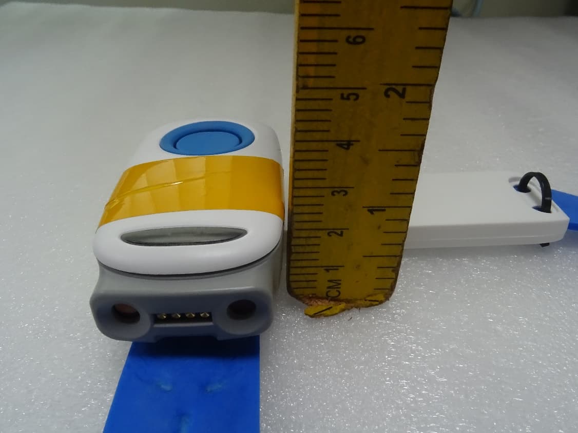
2AZELADCP1P0WB
Apr 13, 2021Cardio Pulmonary Management system
Equipment Class
DTS - Digital Transmission System