2AZIR52840BG95NNBeWhere Asset Tracker
BeWhere Inc.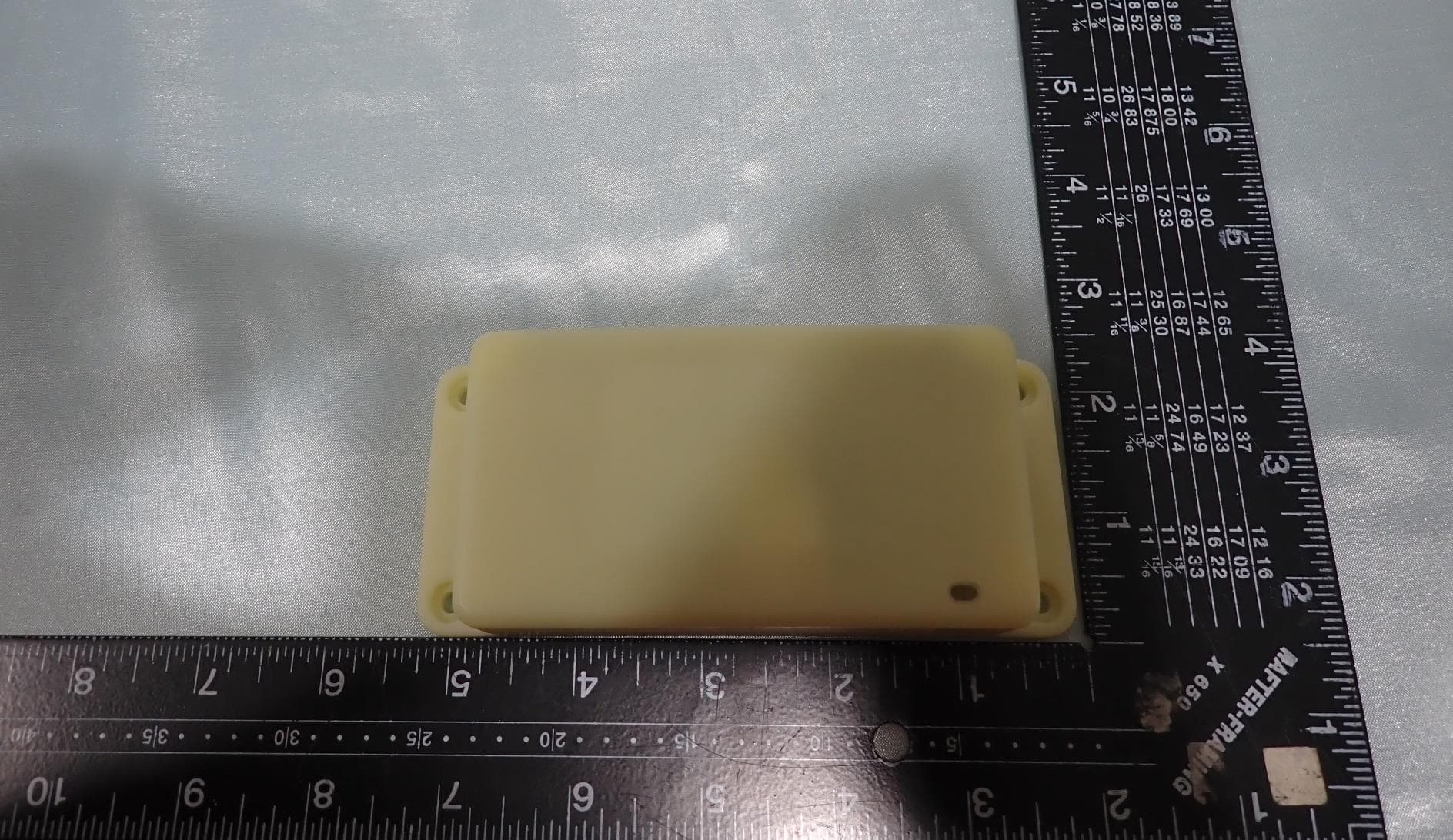
Click to zoom
Application Details
- Equipment Class
- DTS - Digital Transmission System
- Date of Grant
- Apr 09, 2023
- Application Purpose
- Original Equipment
- Date of Application
- Apr 09, 2023
- Equipment Note
- BeWhere Asset Tracker
- Frequency Range
- 2402.00000000 - 2480.00000000
- Company
- BeWhere Inc.
- Country
- Canada
Documents & Files
Document Text
Text extracted from the exhibit documents filed with the FCC. Open a document above to read the original.
Users Manual
Installation Instructions BeSol+ BeWhere, Last updated: October 26th, 2022 BeWhere – Installation Instructions 1 BeWhere – Installation Instructions 2 Installer Qualifications The BeWhere device should be installed properly by a qualified mechanic, after they have reviewed the installation manual. Hardware Included Welcome To BeWhere BeSol •Sun powered rechargeable battery •Mounting Screws •GPS, Temp, Light, Air Pressure, Humidity Sensor IP67/ 100.6 x 56.6 x 33.7 mm / 4x 2.2 x 1.3” Tools and Material Required •BeWhere installation document •Acetone-based cleaner •Clean, absorbent rags and/or towels •Materials for your chosen mounting method (screw, magnet, or VHB tape) shown below For screw mounting •Self-tapping sheet metal screw •Phillips pan head •Zinc plated sheet •Max head diameter 6mm •Bit Size – 4x5/8-inch length Purchase upfront For VHB tape mounting •Cutting tool (scissors, side cutters, or knife) •Double-sided Very High Bond (VHB) tape •Butane torch to heat surface For magnet mounting •Magnet mounting kit •Phillips screwdriver •8-mm wrench or socket Warning Information WARNING: Do not mount any device with antenna side against metal (antenna location shown on page 3) WARNING: Please follow safety precautions for operating and servicing the installation on BeWhere devices CAUTION: Re-Tighten any screws loosen during work period CAUTION: Monitor devices frequently CAUTION: Clean solar panel after use, this allows the device to fully recharge BeSol BeWhere – Installation Instructions 3 STEP 1 Determine the best location on the asset to install the tracker •Choose a location where the top surface of the tracker (Antenna) will have a clear view of the sky (as shown below) •Horizontal mounting is ideal but vertical mounting is acceptable, provided that the top of the tracker has a clear view of the sky •Choose a location where the tracker is unlikely to be damaged or knocked off during normal operation of the asset •If you use screws to mount the tracker, choose a location that is not backed by any element that the screws could be damaged Antenna location STEP 2 Clean the selected location •Use acetone-based cleaner to remove oil, grease, and dirt from the mounting location •Wipe down area with an absorbent rag or towel. •Ensure area in dry before mounting device STEP 3 Mount the tracker on the asset Follow the instructions below , depending on your preferred mounting method IMPORTANT: Do not drive screws into coolant lines, radiators, electrical wiring, fluid tanks, or moving components. Using self-tapping mounting screws supplied: You can use the provided screws to mount the tracker on steel that is up to 1/8inch thick. For thicker steel, use machine screws, magnets, or VHB tape. 1.Place the tracker in the desired location on the asset 2.Using a Phillips Pan Head driver, screw the provided stainless steel self- tapping screws through the mounting holes of the tracker into the asset. Ensure that each screw is seated securely. Top of BeSol Do not overtighten the self-tapping screws as they will crack the base. Insure both sides are equal in tightness. Antenna and GPS Importance BeWhere – Installation Instructions 4 Antenna location It is important not to mount the devices Antenna against metal. If Antenna is mounted against metal, this will block the ability to find the satellite. This will create inaccurate device location and the information being reported. B2 GPS UP Part Numbers B2 – BeSol (BTS) BeSol needs to be mounted with the solar panel facing up. It must be in direct view of the sky. GPS On B2 generation devices, the GPS is located on the top of the PCB board (e.g. under the solar panel). Only B2 BeTen, BeSol, BeWired and BeMini are sold onward. Mounting the devices with GPS directed towards the sky will give the best results. Covered GPS main bounce and be inaccurate. Alternate Mounting Options BeWhere – Installation Instructions 5 IMPORTANT: The setting temperature must be above 0 °C to ensure proper stick. Recommended for lower temperature to heat mounting surface before applying tape. 1.Turn the tracker upside down to expose the underside. 2.Measure the VHB mounting tape to cover the entire bottom of the mounting surface. Cut the tap to fit so that it does not extend beyond the ends of the trackers. 3.Remove the backing from the VHB tape. 4.Following the tape manufacturer’s recommendations, adhere the tracker to the clean, dry surface of the asset. VHB Tape Double-sided tape (VHB) would be placed on the bottom of device Double Sided Tape Double Sided Tape Using Bracket 1.Locate area on asset you would like to install the bracket and device 2.Determine the way you would like your device to sit on the bracket 3.Attach your device to the bracket and then install the bracket to the asset 4.Bracket can either be mounted vertical or horizontal – as long as the GPS/Antenna are away from metal and facing the sky Using VHB Tape– Must be purchased up front at time of order (ie. 3M™ VHB™ Tape is a high-strength, double-sided acrylic adhesive tape) Must be purchased up front at time of order Alternate Mounting Option BeWhere – Installation Instructions 6 Using Magnets Industrial strength magnets are a useful mounting option if the equipment might be re-purposed in the future. 1.Locate area on asset that device will be mounted to with magnetic mount. 2.The magnet bolt is wider than the mounting tab hole on the device. This will need to be drilled out for magnet bolt to fit. | D (mm)| M(mm) | H(mm) | h (mm) | G | KG | Magnet Mount DY32MM Sizing needed shown below: Strong magnetic grip connects to any metal for reliable stability and support Must be purchased up front at time of order Installation Do’s BeWhere – Installation Instructions 7 GPS pointing to the sky, antenna away from the metal, asset in an outdoor location= correct installation which offers the best data. Therefore we recommend using BeSol for outdoor assets management Installation Don’ts BeWhere – Installation Instructi…
Text truncated - open the document above for the full version.
Users Manual
Installation Instructions BeTen+ BeWhere, Last updated: October 26, 2022 BeWhere - Installation Instructions 1 BeWhere – Installation Instructions 2 Installer Qualifications The BeWhere device should be installed properly by a qualified mechanic, after they have reviewed the installation manual. Hardware Included Welcome To BeWhere IP67/ 100.6 x 56.6 x 33.7 mm / 4x 2.2 x 1.3” Tools and Material Required •BeWhere installation document •Acetone-based cleaner •Clean, absorbent rags and/or towels •Materials for your chosen mounting method (screw, magnet, or VHB tape) shown below For screw mounting •Self-tapping sheet metal screw •Phillips pan head •Zinc plated sheet •Max head diameter 6mm •Bit Size – 4x5/8-inch length Purchase upfront For VHB tape mounting •Cutting tool (scissors, side cutters, or knife) •Double-sided Very High Bond (VHB) tape •Butane torch to heat surface For magnet mounting •Magnet mounting kit •Phillips screwdriver •8-mm wrench or socket Warning Information WARNING: Do not mount any device with antenna side against metal (antenna location shown on page 3) WARNING: Please follow safety precautions for operating and servicing the installation on BeWhere devices CAUTION: Re-Tighten any screws loosen during work period CAUTION: Monitor devices frequently BeTen •2AA batteries (replaceable with verified batteries) Purchase battery through BeWhere •GPS, Temp, Light, Air Pressure, Humidity Sensor BeTen BeWhere – Installation Instructions 3 STEP 1 Determine the best location on the asset to install the tracker •Choose a location where the top surface of the tracker (Antenna) will have a clear view of the sky (as shown below) •Horizontal mounting is ideal but vertical mounting is acceptable, provided that the top of the tracker has a clear view of the sky •Choose a location where the tracker is unlikely to be damaged or knocked off during normal operation of the asset •If you use screws to mount the tracker, choose a location that is not backed by any element that the screws could be damaged Antenna location STEP 2 Clean the selected location •Use acetone-based cleaner to remove oil, grease, and dirt from the mounting location •Wipe down area with an absorbent rag or towel. •Ensure area in dry before mounting device STEP 3 Mount the tracker on the asset Follow the instructions below , depending on your preferred mounting method IMPORTANT: Do not drive screws into coolant lines, radiators, electrical wiring, fluid tanks, or moving components. Using self-tapping mounting screws supplied: You can use the provided screws to mount the tracker on steel that is up to 1/8inch thick. For thicker steel, use machine screws, magnets, or VHB tape. 1.Place the tracker in the desired location on the asset 2.Using a Phillips Pan Head driver, screw the provided stainless steel self-tapping screws through the mounting holes of the tracker into the asset. Ensure that each screw is seated securely Top of BeTen Do not overtighten the self-tapping screws as they will crack the base. Insure both sides are equal in tightness. Antenna and GPS Importance BeWhere – Installation Instructions 4 Antenna location It is important not to mount the devices Antenna against metal. If Antenna is mounted against metal, this will block the ability to find the satellite. This will create inaccurate device location and the information being reported. Part Numbers B2 – BeTen (BTB) UP GPS On B2 generation devices, the GPS is located on the top of the PCB board (e.g. under the solar panel). Only B2 BeTen, BeSol, BeWired and BeMini are sold onward. Mounting the devices with GPS directed towards the sky will give the best results. Covered GPS main bounce and be inaccurate. BeTen can be mounted GPS up, or sideways. The device needs an unobstructed view of the sky for accurate GPS and optimal network. B2 GPS Alternate Mounting Options BeWhere – Installation Instructions 5 IMPORTANT: The setting temperature must be above 0 °C to ensure proper stick. Recommended for lower temperature to heat mounting surface before applying tape. 1.Turn the tracker upside down to expose the underside. 2.Measure the VHB mounting tape to cover the entire bottom of the mounting surface. Cut the tap to fit so that it does not extend beyond the ends of the trackers. 3.Remove the backing from the VHB tape. 4.Following the tape manufacturer’s recommendations, adhere the tracker to the clean, dry surface of the asset. VHB Tape Double-sided tape (VHB) would be placed on the bottom of device Double Sided Tape Double Sided Tape Using Bracket 1.Locate area on asset you would like to install the bracket and device 2.Determine the way you would like your device to sit on the bracket 3.Attach your device to the bracket and then install the bracket to the asset 4.Bracket can either be mounted vertical or horizontal – as long as the GPS/Antenna are away from metal and facing the sky Using VHB Tape– Must be purchased up front at time of order (ie. 3M™ VHB™ Tape is a high-strength, double-sided acrylic adhesive tape) Must be purchased up front at time of order Alternate Mounting Option BeWhere – Installation Instructions 6 Using Magnets Industrial strength magnets are a useful mounting option if the equipment might be re-purposed in the future. 1.Locate area on asset that device will be mounted to with magnetic mount. 2.The magnet bolt is wider than the mounting tab hole on the device. This will need to be drilled out for magnet bolt to fit. | D (mm)| M(mm) | H(mm) | h (mm) | G | KG | Magnet Mount DY32MM Sizing needed shown below: Strong magnetic grip connects to any metal for reliable stability and support Must be purchased up front at time of order Battery Slide BeWhere – Installation Instructions 7 Installation Do’s BeWhere – Installation Instructions 8 Antenna facing AWAY from metal Installation Don’ts BeWhere – Installation Instructions 9 -GPS is covered -Cell antenna is up against metal and/or covered -Limited sun exposure Antenna This will relate to poor netw…
Text truncated - open the document above for the full version.
Users Manual
Installation Instructions BeWired BeWhere, Last updated: October 26 2022 BeWired wiring installation •Disregard Sensor Cable unless you purchased a specific BeWhere Solution. •Ensure the device is in view of the sky after wiring for GPS and Network optimization Connections Information Screw Cable Gland Compliant to IP67 Cable (L) Red or pink IMPORTANT: If you do not require the additional wires make sure you cut or discard them. Also make sure the metal wiring is not exposed or touching each other Additional Wires Welcome To BeWhere Thank you for choosing BeWhere! BeWhere - Installation Instructions 3 Installer Qualifications The BeWhere device should be installed properly by a qualified 12V technician, after they have reviewed the installation manual. Tools and Material Required •BeWhere installation document •Materials for your chosen mounting method (screw, magnet, or tape) shown below •Multimeter •Drill •Wire cutters •Wire strippers •Heat gun •Crimper •(2) Self-tapping sheet metal screw •(use provided screws) Hardware Included BeWired •Ignition powered rechargeable battery •GPS, Temp, Light, Air Pressure, Humidity Sensor IP67/ 100.6 x 56.6 x 33.7 mm / 4x 2.2 x 1.3” Warning Information For screw mounting For tape mounting •Double-sided Very High Bond (VHB) tape •Rubbing alcohol / alcohol wipes •(2) 5mm diameter zip ties Additional Mounting Options Additional Parts (not supplied) -(2) ATC fuse holders (18 Gauge) -(2) 3-AMP ATC fuses -Heat shrink Butt connectors (assorted) -Heat shrink Ring terminals (assorted) WARNING: Do not mount any device with antenna side against metal WARNING: Please follow safety precautions for operating and servicing the installation on BeWhere devices TIP: Inspect device frequently Tip: Re-Tighten any screws that loosened during the work period Cable Tie or Zip Tie Multimeter If you are using a Multimeter: •Set the meter to read DC volts (200 volt range or auto) •Ensure that the probes are plugged into the ground and voltage-measuring sockets, not into the current-measuring socket (marked A for amps).Double-check the meter setup before you make any test connections. •Ensure that the meter’s ground lead is securely connected to the chassis of the asset BeWhere - Sales 4 Measure voltages only at the connection terminals. Never poke into existing wires for testing as this damages the insulation. Step 1 BeWhere - Sales 5 5. Install ring terminal connectors on constant, ignition, and ground leads Note: Heat shrink all ring terminal connections after ring terminals have been crimped 6. Connect the black wire (with ring terminal attached) to the asset’s alternator ground connection. 7. Connect the red wire (with ring terminal attached) to asset’s constant power terminal on the alternator. 8. Connect the grey wire (with ring terminal attached) to asset’s ignition power source. 9. If ring terminals are not able to be used for connections wires must be cut and spliced with heat shrink butt connectors How to find a continuous power source Using a DC voltage multimeter probe, measure voltage on all three terminals of the alternator (Main power is usually the largest post to the alternator): 1.For the power source: Locate a 6.5V-40V(DC) source of continuous power 2. When assets ignition is off, verify that voltage is still present in the constant power source DC 6.5V-40V Continuous Power Source 3. Plan the cable routing path(see step 4 for additional information) 4. Prepare the tracker’s power cables (red is constant and black is ground) and ignition cable (grey) Recommended: Install fuse holders with 3-AMP fuses on constant and ignition power leads Example: A. Tracker power cable (black wire) connected to the alternator's ground connection. B. Tracker’s power cable (red wire) connected to positive alternator terminal. Step 2 BeWhere - Sales 6 How to find an ignition source 1.Ensure that the equipment ignition is in the OFF position. 2.Connect the negative lead of a Multimeter to the asset’s ground connection which you plan to attach the ground wire on the tracker 3.Use a multimeter to check the voltage. Verify that the voltage is zero. 4.Turn on the ignition and start the equipment. 5. With the multimeter, verify that the ignition source voltage is at least between 5.5V-40V 6. Turn the ignition to the OFF position and verify that the voltage returned to zero. •If the voltage did not drop to zero after you switched off the ignition, that connection is not an ignition-signal source. Find a suitable ignition source. 7.If the voltage at this point cycles on and off with the ignition switch, you have found a suitable ignition- signal source. BeWhere - Sales 7 Secure the cables 1.Inspect the wire connections to ensure safe conditions: •All wires are connected correctly. •All connections are watertight. 2.Inspect the routing for the tracker’s power, ignition, breakout, and tracker cables to ensure safe conditions: •Cables are not pinched. •Cables are no exposed to sharp edges. •Cables are not near a heat source. •Cables are not near moving parts. •Cables are not swinging or dangling. •There are no long, unsecured runs. Ground Source Ignition Source Device Wire Constant Power Source Note: The red wire may appear as pink Additional Wires IMPORTANT: If you do not require the additional wires make sure you cut or discard them. Also make sure the metal wiring is not exposed or touching each other Step 3 BeWhere - Sales 8 •If you must enclose the tracker, use a nonmetallic housing and ensure that the tracker has good visibility to the sky through enclosure. •The tracker will not function well when placed in an area where the GPS or cellular antenna is facing metal such as inside a metal cabinet or case, or on the underside of the equipment. •If you use screws to mount the tracker, choose a location that is not backed by any component that the screws could damage, such a coolant lines, radiators, electrical wiring fluid tanks, or moving components. •You must be able…
Text truncated - open the document above for the full version.
Attestation Statements
DocuSign Envelope ID: BD3A77B3-DB2C-4B96-B343-2B4F37230646 BeWhere Inc. 3264 Lake Shore Blvd W, Etobicoke, Canada M8V 1M4 Tel: 8442294373; Fax: 2898007135 Federal Communications Commission 7435 Oakland Mills Road Columbia MD 21046 Subject: Certification designating a U.S. agent for service of process pursuant to Part 2.911(d)(7) To whom it may concern, [ BeWhere Inc., Grantee Code 2AZIR] (“the applicant”) certifies that, as of the date of the filing of application, [BEWHERE INC.] (“the agent”) is designated as the U.S. agent for the purpose of accepting service of process on behalf of the applicant. The physical U.S. address and email for the designated agent are: Physical U.S. address: [1958 BUTLER PIKE #506 CONSHOHOCKEN, PA 19428] USA FRN: 0033556101 Email: [[email protected]] The applicant accepts to maintain an agent for service of process in the United States for no less than one year after either the grantee has permanently terminated all marketing and importation of the applicable equipment within the U.S., or the conclusion of any Commission-related administrative or judicial proceeding involving the equipment, whichever is later. The agent accepts the designation by (the applicant) as the U.S. agent to accept service of process includes, but is not limited to, delivery of any correspondence, notices, orders, decisions, and requirements of administrative, legal, or judicial process related to Commission proceedings. Signed by the Applicant Signed by the Agent (if different from the Applicant) Name: Owen Moore Name: Chris Panczuk Title: CEO Title:COO Email: [email protected] Email: [email protected] Date: March 20, 2023 Date: March 20, 2023
Attestation Statements
BeWhere Inc. 3264 Lake Shore Blvd W, Etobicoke, Canada M8V 1M4 Tel: 8442294373 ; Fax: 2898007135 Federal Communications Commission 7435 Oakland Mills Road Columbia MD 21046 Date: February 7, 2023 Subject: Certifications concerning “covered” equipment pursuant to Part 2.911(d)(5)(i) and (ii) To whom it may concern, [BeWhere Inc.] (“the applicant”) certifies that the equipment [FCC ID: 2AZIR52840BG95NN] for which authorization is sought is not “covered” equipment prohibited from receiving an equipment authorization pursuant to section 2.903 of the FCC rules. [BeWhere Inc.] (“the applicant”) certifies that, as of the date of the filing of the application, the applicant [is not] identified on the Covered List as an entity producing “covered” equipment. Sincerely, ________________________ Owen Moore [email protected] DocuSign Envelope ID: F5F7C9DB-CBD2-42F8-B019-D4A9F944A97F
Cover Letter(s)
BeWhere Inc. 2475 Skymark Ave Unit, Mississauga, ON L4W 4Y6 Tel: 8442294373 ; Fax: 2898007135 Date: November 15, 2022 FCC Laboratory 7435 Oakland Mills Rd Columbia MD 21046 Subject: Request for Confidentiality FCC ID: 2AZIR52840BG95NN To Whom It May Concern, Pursuant to the provisions of Sections 0.457 and 0.459 of Commission’s rules (47CFR§§0.457, 0.459), we are requesting the Commission to withhold the following documents from public disclosure indefinitely. Schematic Diagram Block Diagram Part List Operational Description Above mentioned documents which contain detailed system and equipment description are considered as proprietary information in operation of the equipment. The public disclosure of above documents might be harmful to our company and would give competitor an unfair advantage in the market. In additional to above mentioned documents, pursuant to Public Notice DA 04-1705 of the Commission’ s policy, in order to comply with the marketing regulations in 47 CFR §2.803 and the importation rules in 47 CFR §2.1204, while ensuring that business sensitive information remains confidential until the actual marketing of newly authorized devices, we are requesting the Commission to withhold the following documents for 180 days after the grant of equipment authorization is issued: External Photos Internal Photos Test Setup Photos User Manual It is our understanding that all measurement test reports, FCC ID label format cannot be granted as confidential documents and those information will be available for public review once the grant of equipment authorization is issued. Best Regards, _______________________ Owen Moore [email protected] DocuSign Envelope ID: B06469B6-31E1-4E7D-AB5B-3F96799DE288
Cover Letter(s)
BeWhere Inc. 2475 Skymark Ave Unit, Mississauga, ON L4W 4Y6 Tel: 8442294373 ; Fax: 2898007135 FCC Agent Authorization Date: November 15, 2022 To whom it may concern, BeWhere Inc. hereby authorize Sporton International Inc. to act on our behalf in all matters relating to applications for FCC equipment authorization, including the signing of all documents relating to these matters. Any and all acts carried out by Sporton International Inc. on our behalf shall have the same effect as acts of our own. We also hereby certify that neither the applicant nor any party to the application is subject to a denial of Federal benefits that includes FCC benefits pursuant to section 5301 of the Anti-Drug Abuse Act of 1988. 21 U.S.C. 862. This authorization is limited to the product of as following: FCC ID: 2AZIR52840BG95NN This authorization is valid until further written notice from BeWhere Inc. Sincerely, ________________________ Owen Moore [email protected] DocuSign Envelope ID: 8409C450-EC92-496D-B2EC-84C94FB2B271
External Photos
PHOTOGRAPHS OF EUT Report No.: EP221102001 TEL : 408 9043300 Page Number : 1 of 61 Issue Date : Mar. 27, 2023 Report Version : 03 1. External Photograph of EUT Brand Name: BeWhere Model Name: B4-MIOT-MR BSP B4-MIOT-MR BTP B4-MIOT-MR BTW Sample 1 PHOTOGRAPHS OF EUT Report No.: EP221102001 TEL : 408 9043300 Page Number : 2 of 61 Issue Date : Mar. 27, 2023 Report Version : 03 PHOTOGRAPHS OF EUT Report No.: EP221102001 TEL : 408 9043300 Page Number : 3 of 61 Issue Date : Mar. 27, 2023 Report Version : 03 PHOTOGRAPHS OF EUT Report No.: EP221102001 TEL : 408 9043300 Page Number : 4 of 61 Issue Date : Mar. 27, 2023 Report Version : 03 PHOTOGRAPHS OF EUT Report No.: EP221102001 TEL : 408 9043300 Page Number : 5 of 61 Issue Date : Mar. 27, 2023 Report Version : 03 PHOTOGRAPHS OF EUT Report No.: EP221102001 TEL : 408 9043300 Page Number : 6 of 61 Issue Date : Mar. 27, 2023 Report Version : 03 PHOTOGRAPHS OF EUT Report No.: EP221102001 TEL : 408 9043300 Page Number : 7 of 61 Issue Date : Mar. 27, 2023 Report Version : 03 Sample 2 PHOTOGRAPHS OF EUT Report No.: EP221102001 TEL : 408 9043300 Page Number : 8 of 61 Issue Date : Mar. 27, 2023 Report Version : 03 PHOTOGRAPHS OF EUT Report No.: EP221102001 TEL : 408 9043300 Page Number : 9 of 61 Issue Date : Mar. 27, 2023 Report Version : 03 PHOTOGRAPHS OF EUT Report No.: EP221102001 TEL : 408 9043300 Page Number : 10 of 61 Issue Date : Mar. 27, 2023 Report Version : 03 PHOTOGRAPHS OF EUT Report No.: EP221102001 TEL : 408 9043300 Page Number : 11 of 61 Issue Date : Mar. 27, 2023 Report Version : 03 PHOTOGRAPHS OF EUT Report No.: EP221102001 TEL : 408 9043300 Page Number : 12 of 61 Issue Date : Mar. 27, 2023 Report Version : 03 PHOTOGRAPHS OF EUT Report No.: EP221102001 TEL : 408 9043300 Page Number : 13 of 61 Issue Date : Mar. 27, 2023 Report Version : 03 Sample 3 PHOTOGRAPHS OF EUT Report No.: EP221102001 TEL : 408 9043300 Page Number : 14 of 61 Issue Date : Mar. 27, 2023 Report Version : 03 PHOTOGRAPHS OF EUT Report No.: EP221102001 TEL : 408 9043300 Page Number : 15 of 61 Issue Date : Mar. 27, 2023 Report Version : 03 PHOTOGRAPHS OF EUT Report No.: EP221102001 TEL : 408 9043300 Page Number : 16 of 61 Issue Date : Mar. 27, 2023 Report Version : 03 PHOTOGRAPHS OF EUT Report No.: EP221102001 TEL : 408 9043300 Page Number : 17 of 61 Issue Date : Mar. 27, 2023 Report Version : 03 PHOTOGRAPHS OF EUT Report No.: EP221102001 TEL : 408 9043300 Page Number : 18 of 61 Issue Date : Mar. 27, 2023 Report Version : 03 PHOTOGRAPHS OF EUT Report No.: EP221102001 TEL : 408 9043300 Page Number : 19 of 61 Issue Date : Mar. 27, 2023 Report Version : 03 PHOTOGRAPHS OF EUT Report No.: EP221102001 TEL : 408 9043300 Page Number : 20 of 61 Issue Date : Mar. 27, 2023 Report Version : 03 2. Photograph of Accessory Brand Name: BeWhere Model Name: B4-MIOT-MR BSP B4-MIOT-MR BTP B4-MIOT-MR BTW Specification of Accessory Battery 1 for B4-BeSol + Brand Name Bewhere Model Name XM1138114 Battery 2 for B4-BeTen + Brand Name Bewhere Model Name ER17505M-2 Battery 3 for B4-Bewired Brand Name Bewhere Model Name HWE103662 M8 Cable for B4-Bewired Brand Name Bewhere Model Name N/A Remark: For accessories equipped with this EUT, please refer to the following photos. PHOTOGRAPHS OF EUT Report No.: EP221102001 TEL : 408 9043300 Page Number : 21 of 61 Issue Date : Mar. 27, 2023 Report Version : 03 Battery 1 for B4-BeSol + PHOTOGRAPHS OF EUT Report No.: EP221102001 TEL : 408 9043300 Page Number : 22 of 61 Issue Date : Mar. 27, 2023 Report Version : 03 Battery 2 for B4-BeTen + PHOTOGRAPHS OF EUT Report No.: EP221102001 TEL : 408 9043300 Page Number : 23 of 61 Issue Date : Mar. 27, 2023 Report Version : 03 PHOTOGRAPHS OF EUT Report No.: EP221102001 TEL : 408 9043300 Page Number : 24 of 61 Issue Date : Mar. 27, 2023 Report Version : 03 PHOTOGRAPHS OF EUT Report No.: EP221102001 TEL : 408 9043300 Page Number : 25 of 61 Issue Date : Mar. 27, 2023 Report Version : 03 Battery 3 for B4-Bewired PHOTOGRAPHS OF EUT Report No.: EP221102001 TEL : 408 9043300 Page Number : 26 of 61 Issue Date : Mar. 27, 2023 Report Version : 03 M8 Cable for B4-Bewired PHOTOGRAPHS OF EUT Report No.: EP221102001 TEL : 408 9043300 Page Number : 27 of 61 Issue Date : Mar. 27, 2023 Report Version : 03 PHOTOGRAPHS OF EUT Report No.: EP221102001 TEL : 408 9043300 Page Number : 28 of 61 Issue Date : Mar. 27, 2023 Report Version : 03
ID Label/Location Info
Bottom of the device Label Location
Internal Photos
PHOTOGRAPHS OF EUT Report No.: EP221102001 TEL : 408 9043300 Page Number : 29 of 61 Issue Date : Mar. 27, 2023 Report Version : 03 3. Internal Photograph of EUT Brand Name: BeWhere Model Name: B4-MIOT-MR BSP B4-MIOT-MR BTP B4-MIOT-MR BTW Sample 1 PHOTOGRAPHS OF EUT Report No.: EP221102001 TEL : 408 9043300 Page Number : 30 of 61 Issue Date : Mar. 27, 2023 Report Version : 03 PHOTOGRAPHS OF EUT Report No.: EP221102001 TEL : 408 9043300 Page Number : 31 of 61 Issue Date : Mar. 27, 2023 Report Version : 03 Sample 2 PHOTOGRAPHS OF EUT Report No.: EP221102001 TEL : 408 9043300 Page Number : 32 of 61 Issue Date : Mar. 27, 2023 Report Version : 03 Sample 3 PHOTOGRAPHS OF EUT Report No.: EP221102001 TEL : 408 9043300 Page Number : 33 of 61 Issue Date : Mar. 27, 2023 Report Version : 03 PHOTOGRAPHS OF EUT Report No.: EP221102001 TEL : 408 9043300 Page Number : 34 of 61 Issue Date : Mar. 27, 2023 Report Version : 03 PHOTOGRAPHS OF EUT Report No.: EP221102001 TEL : 408 9043300 Page Number : 35 of 61 Issue Date : Mar. 27, 2023 Report Version : 03 Sample 1 PHOTOGRAPHS OF EUT Report No.: EP221102001 TEL : 408 9043300 Page Number : 36 of 61 Issue Date : Mar. 27, 2023 Report Version : 03 PHOTOGRAPHS OF EUT Report No.: EP221102001 TEL : 408 9043300 Page Number : 37 of 61 Issue Date : Mar. 27, 2023 Report Version : 03 PHOTOGRAPHS OF EUT Report No.: EP221102001 TEL : 408 9043300 Page Number : 38 of 61 Issue Date : Mar. 27, 2023 Report Version : 03 PHOTOGRAPHS OF EUT Report No.: EP221102001 TEL : 408 9043300 Page Number : 39 of 61 Issue Date : Mar. 27, 2023 Report Version : 03 PHOTOGRAPHS OF EUT Report No.: EP221102001 TEL : 408 9043300 Page Number : 40 of 61 Issue Date : Mar. 27, 2023 Report Version : 03 PHOTOGRAPHS OF EUT Report No.: EP221102001 TEL : 408 9043300 Page Number : 41 of 61 Issue Date : Mar. 27, 2023 Report Version : 03 Sample 2 PHOTOGRAPHS OF EUT Report No.: EP221102001 TEL : 408 9043300 Page Number : 42 of 61 Issue Date : Mar. 27, 2023 Report Version : 03 PHOTOGRAPHS OF EUT Report No.: EP221102001 TEL : 408 9043300 Page Number : 43 of 61 Issue Date : Mar. 27, 2023 Report Version : 03 PHOTOGRAPHS OF EUT Report No.: EP221102001 TEL : 408 9043300 Page Number : 44 of 61 Issue Date : Mar. 27, 2023 Report Version : 03 PHOTOGRAPHS OF EUT Report No…
Text truncated - open the document above for the full version.
Contact Information
Applicant
Owen Moore(CEO)
Test Firm
Sporton International (USA) IncKevin Lu
[email protected]16692729004
Technical Specifications
| # | Rule Parts | Frequency Range | Power Output |
|---|---|---|---|
| 1 | 15C | 2.40 GHz - 2.48 GHz | 2.10 mW |