Text extracted from the exhibit documents filed with the FCC. Open a document above to read the original.
1 | P a g e D-001518 rev 00 . 1.1 The case is made of a recyclable ABS-PC blended material for high strength. 1.2 The instrument, including the USB port, is rated to IP65 for Ingress Protection from dust and water. This device complies with part 15 of the FCC Rules. Operation is subject to the following two conditions: (1) This device may not cause harmful interference, and (2) this device must accept any interference received, including interference that may cause undesired operation. Changes or modifications not expressly approved by Alcotek, Inc. for compliance could void the user's authority to operate the equipment. NOTE: This equipment has been tested and found to comply with the limits for a Class B digital device, pursuant to part 15 of the FCC Rules. These limits are designed to pro-vide reasonable protection against harmful interference in a residential installation. This equipment generates, uses and can radiate radio frequency energy and, if not in-stalled and used in accordance with the instructions, may cause harmful interference to radio communications. However, there is no guarantee that interference will not occur in a particular installation. If this equipment does cause harmful interference to radio or television reception, which can be determined by turning the equipment off and on, the user is encouraged to try to correct the interference by one or more of the following measures: —Reorient or relocate the receiving antenna. —Increase the separation between the equipment and receiver. —Connect the equipment into an outlet on a circuit different from that to which the receiver is connected. —Consult the dealer or an experienced radio/ TV technician for help. FCC Radiation Exposure Statement “This equipment complies with FCC radiation exposure limits set forth for an uncontrolled environment. This equipment is in direct contact with the body of the user under normal operating conditions. This transmitter must not be co-located or operating in conjunction with any other antenna or transmitter.” 2 | P a g e D-001518 rev 00 1.3 The case includes a breathable membrane to avoid any pressurization or condensation within the case while maintaining IP65 protection. 1.4 The instrument is equipped with an internal Lithium-ion rechargeable battery. The battery may be charged through the USB port. 1.5 The instrument may communicate with other devices through the USB port. 1.6 The instrument is equipped with a wireless (BLE) transmit and receive capability, including a built-in antenna. 3.1 TURN ON: Hold down momentarily, then release switch. 3.2 The following screen will appear for approximately one second: 3.3 Followed by the Data Mode screen: Red Alarm LED OLED Display (128 x 64) (4) Function Switches Red Alarm LED Enter (Select) Alcotek Inc Ver.0.7.3 67% -- 3 | P a g e D-001518 rev 00 3.4 TURN OFF: 3.5 ALTERNATE TURN OFF: Starting with the Data Mode screen mentioned in 3.3 above: Menu item “POWER DOWN” is highlighted. Press momentarily to accept and unit will turn off. 4.1 Use to scroll down to the lower part of this menu: 4.2 Press momentarily to return to Data Mode, as shown below. Use to navigate up and down the menu. Enter (Select) Main Menu Commands General Setup Main Screen Setup Power Down Use to select a highlighted menu item. 67% -- Battery Indicator No Tilt Data Indicator Exit (Cancel) Enter (Select) 67% -- Enter (Cancel) Exit (Cancel) --- 67% -- Enter (Cancel) Exit (Cancel) --- --- 1. Hold down Exit switch until a single bar displays above. 2. Continue to hold down Exit switch until a second bar displays above. Now release switch; unit will power down. 67% -- Enter (Cancel) Exit (Cancel) --- 1. Hold down Exit switch until a single bar displays above. Main Menu Commands General Setup Main Screen Setup Power Down 2. Release Exit switch and the screen will change to the Menu Mode screen. The white portion of the menu bar indicates how much of the current menu is being displayed Main Menu Warnings Voltages Exit Menu Main Screen Setup 4 | P a g e D-001518 rev 00 5.1 Turn Sensing Unit ON to get a slowly flashing green LED. See Operating Manual for Sensing Unit for more details. 5.2 Turn Operator Interface ON as in 3.1 above. 5.3 On Sensing Unit, hold down until the red LED flashes once. This turns on BLE advertising from the Sensing Unit. 5.4 Press on Operator Interface until one line appears above that switch on the display, then release. 5.5 Angles should begin appearing on the Operator Interface that represent the position of the Sensing Unit in real time as shown here. 5.6 The Menu Mode may be used to change the characteristics of the display screen i.e. what is displayed and where. An example is shown here: 6.1 Power Down 6.2 Commands 6.2.1 Scanning 6.2.2 Disconnect 6.2.3 Start Filing 6.2.4 Stop Filing 6.2.5 Tare 6.2.6 Save Calibration 6.2.7 Back Tilt Data Data Type Enter (Select) 67% 15º 0º - PITCH - ROLL UFC NOTE: “U” in the left upper corner of the display indicates the sensor unit is connected as a USB drive to PC. “F” in upper left corner of the display indicates that the BLE linked Sensing Unit is currently saving data to a file in the Sensing Unit. “C” in the upper left corner indicates the Sensing Unit is charging. 67% 91% Sensing Unit battery indicator 67% 24% 91% GRADE 5 | P a g e D-001518 rev 00 6.3 General Setup 6.3.1 Power Up Scan 6.3.2 Positive Display 6.3.3 Back 6.4 Main Screen Setup 6.4.1 Number of Items 6.4.2 Right 6.4.2.1 Items 6.4.2.2 Units of Measure 6.4.2.3 Use sign 6.4.2.4 Digits 6.4.3 Left 6.4.3.1 Items 6.4.3.2 Units of Measure 6.4.3.3 Use sign 6.4.3.4 Digits 6.4.4 Back 6.5 Warnings 6.6 Voltages 6.7 Exit Menu 7.0 7.1 Power Down – Turns the Operator Interface off. 7.2 Commands – Brings up the following sub-menu. 7.2.1 Scanning – Starts a scan for a Sensing Unit ready to be paired. Displays “Scanning Started.” then returns to the previous menu. If pairing is successful, data will be displayed in the Data Mode. 7.2.2 Disconnect – Disconnects the Ope…
Text truncated - open the document above for the full version.
150 Hanley Industrial Court, Saint Louis, Missouri 63144 phone 314.644.3244 fax 314.644.4308 www.alcotek.com ® Authority to Act as Agent Date: March 28, 2021 American Certification Body, Inc. 6731 Whittier Avenue Suite C110 McLean, VA 22101 To Whom It May Concern: D.L.S. Electronic Systems, Inc is authorized to act on our behalf, until otherwise notified, for applications to American Certification Body, Inc. (ACB). We certify that we are not subject to denial of federal benefits, that includes FCC benefits, pursuant to Section 5301 of the Anti-Drug Abuse Act of 1988, 21 U.S.C. 862. Further, no party, as defined in 47 CFR 1.2002 (b), to the application is subject to denial of federal benefits, that includes FCC benefits. We also declare that the information provided to the FCC is true and correct to the best of our knowledge (47 CFR 2.911(d)) and we have been informed of the grantee responsibilities (47 CFR 2.909) with regard to certified equipment. Thank you, Agency Agreement Expiration Date: ___March 28, 2022__ By: __________________________ KARL R WOLF (Signature) (Print name) Title: PRESIDENT On behalf of: ALCOTEK, INC. (Company Name) Telephone: 314-644-3244
150 Hanley Industrial Court, Saint Louis, Missouri 63144 phone 314.644.3244 fax 314.644.4308 www.alcotek.com ® Request for Confidentiality Date: April 16, 2021 Subject: Confidentiality Request for: FCC ID: 2AZIU21-1374 Pursuant to FCC 47 CFR 0.457(d) and 0.459 the applicant requests that a part of the subject FCC application be held confidential. Type of Confidentiality Requested Exhibit ☐ Short Term ☒ Permanent Block Diagrams ☒ Short Term External Photos ☒ Short Term ☐ Permanent Internal Photos ☐ Short Term ☒ Permanent Operation Description/Theory of Operation ☐ Short Term ☐ Permanent Parts List & Placement/BOM ☐ Short Term ☐ Permanent Tune-Up Procedure ☐ Short Term ☒ Permanent Schematics ☒ Short Term Test Setup Photos ☒ Short Term ☐ Permanent User’s Manual Alcotek, Inc. has spent substantial effort in developing this product and it is one of the first of its kind in industry. Having the subject information easily available to "competition" would negate the advantage they have achieved by developing this product. Not protecting the details of the design will result in financial hardship. Permanent Confidentiality: The applicant requests the exhibits listed above as permanently confidential be permanently withheld from public review due to materials that contain trade secrets and proprietary information not customarily released to the public. Short-Term Confidentiality: The applicant requests the exhibits selected above as short term confidential be withheld from public view for a period of 180 days from the date of the Grant of Equipment Authorization and prior to marketing. This is to avoid premature release of sensitive information prior to marketing or release of the product to the public. Applicant is also aware that they are responsible to notify ACB in the event information regarding the product or the product is made available to the public before the requested period has expired. ACB will then release the documents listed above for public disclosure pursuant to FCC Public Notice DA 04-1705. Sincerely, By: __________________________ ________________________ (Signature/Title) (Print name)
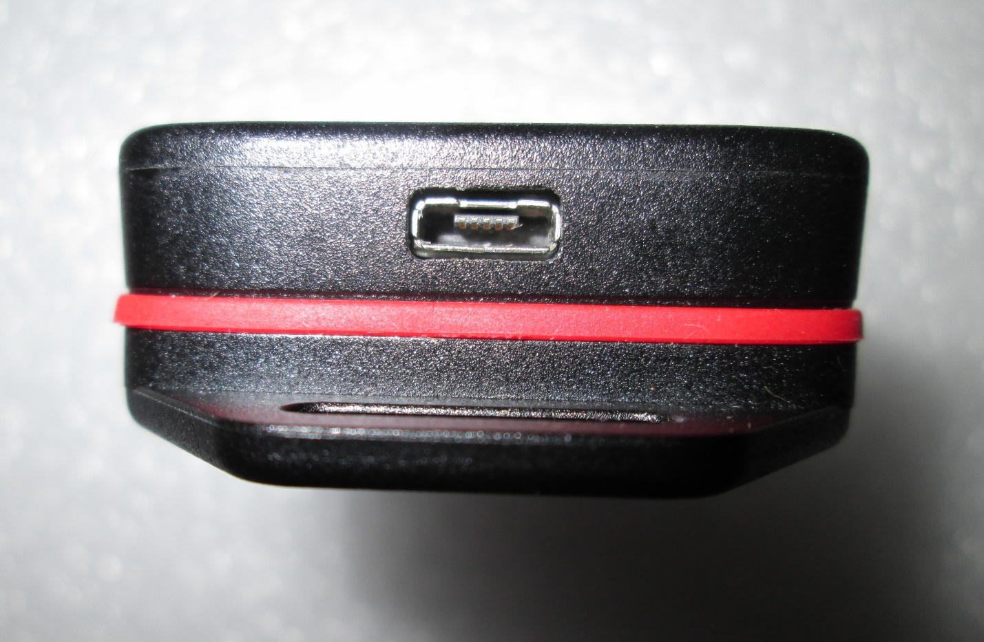
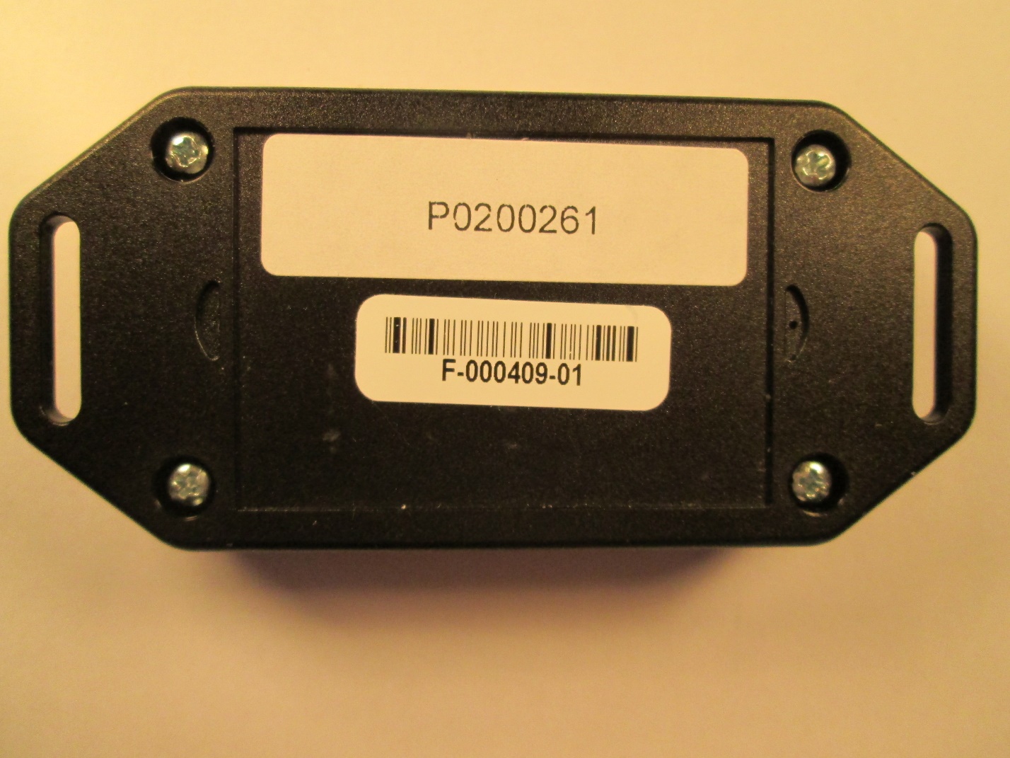
External Photographs Alcotek, Inc. TILT Angle Sensor Model F-000409-01 Operator Interface Top (Face) of EUT External Photographs Alcotek, Inc. TILT Angle Sensor Model F-000409-01 Operator Interface Bottom (Back) of EUT External Photographs Alcotek, Inc. TILT Angle Sensor Model F-000409-01 Operator Interface Side of EUT Side of EUT (USB Port)
Tilt 1 OF 3 SIL 5/06/2020 1:1 .007 Clear Marnot XL Advanced PETAdhesive: 3M #7956 Title: Date: Originator: Sheet: Scale: Tolerance: Material: Size: First Used: Part: A ECN: Init: Date: Rev: Description: ALCOTEK, INC. 1. “Wireless Connectivity” Font: Arial 5pt2. “FCC ID: 2AZIU21-1374” Font: Arial 5pt3. “Operator Interface” Font: Arial 5pt4. “Exit ” “ Enter ” Font: Arial 10pt 5. “ (Cancel) ” “ (Select) ” Font: Arial Italic 6pt 6. Background: PANTONE SIGNAL RED 485 C7. Fonts and borders: PANTONE BLACK8. Void areas are clear membrane9. Copy and Background printed Subsurface 10. UV Texture applied overall surface side (Except clear windows) A 5/6/2020 Release 2261 SL Wireless Connectivity FCC ID: 2AZIU21-1374 SW00037-01 Membrane, Tilt, Display (Select) (Cancel) Enter Exit Operator Interface B 4/9/2021 2394 SL Updtd inst,mtl, added FCC #, switch position (Select) (Cancel) Enter Exit Operator Interface Wireless Connectivity FCC ID: 2AZIU21-1374 Sheet 3 of 3 LABEL, MEMBRANESWITCH ASSEMBLY RECESS IN CASE TOP CASE TOP HALF CASE BOTTOM HALF NOTE: LABEL ATTACHED TO CASE WITH PERMANENT ADHESIVE 3M#7956 POSITION LABEL ASSEMBLY
Internal Photographs Alcotek, Inc. TILT Angle Sensor Model F-000409-01 Operator Interface Inside Bottom of EUT Internal Photographs Alcotek, Inc. TILT Angle Sensor Model F-000409-01 Operator Interface Inside Assembly Internal Photographs Alcotek, Inc. TILT Angle Sensor Model F-000409-01 Operator Interface Bottom of PBC Board with battery Internal Photographs Alcotek, Inc. TILT Angle Sensor Model F-000409-01 Operator Interface Bottom of PC Board with Battery Removed Internal Photographs Alcotek, Inc. TILT Angle Sensor Model F-000409-01 Operator Interface Top of PC Board Internal Photographs Alcotek, Inc. TILT Angle Sensor Model F-000409-01 Operator Interface Side of PC Board