2AZJ2-A17True Wireless Sports Earbuds
Dongguan Yinwo Electronic Technology Co., Ltd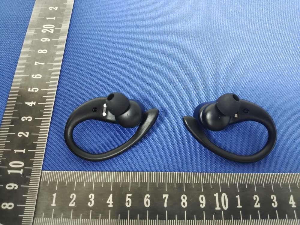
Click to zoom
Application Details
- Equipment Class
- DSS - Part 15 Spread Spectrum Transmitter
- Date of Grant
- May 08, 2023
- Application Purpose
- Original Equipment
- Date of Application
- May 08, 2023
- Equipment Note
- True Wireless Sports Earbuds
- Frequency Range
- 2402.00000000 - 2480.00000000
- Country
- China
Documents & Files
Document Text
Text extracted from the exhibit documents filed with the FCC. Open a document above to read the original.
Users Manual
曰口L口X口 A17 _User Manual True Wireless S p orts Earbuds _ d t 戏。。 b WWw b e w m dIt a x5 07 4 。 b0 @49 3 t 2 。 9 p p 3 SU n 6 8 . + a E( 5 E ep A s t sa a eh w ft A 曰回 User Manual• 1 piece Wireless Earbud• 1 pair Charging Case• 1 piece S oft Ear Tips• 3 pairs(M size on Earbud) Ty pe-C Charging Cable• 1 piece _ Model NO.: A17 Charging Time: about 2Hrs Input: 5V= 1A Support: MC/A2DP/HFP/HSP/AVRCP Capacity: 3.7V 600mAh, 2.22Wh Charging Supported: Yes Charging Port: Type-C (chargi叨pad not included) FCC ID: 2AZJ2-A17 Transmission Rang: 33 feet(w1tholl'I obstacle) _ 01 Multi-function Button (MFB) Battery庄D Dispeiy of Charging Case Cha『gingPins on Charg, ng Case Ear tips Charging Case Power Status 02 Secure Ear-hook LED Indicator d心1nq Po 呻&Rig 1. Please remove the protective film before use, otherwise the he的phone will not be able to charge Tear off the protective film 2. Choose suitable ear tips & Wear correctly to enhance sound quality c- f-t 3, Please clean the protective grille of both earbuds if the sound becomes low, Protective Grille • To make sound louder 03 4. Please clean the magnet charging dot on earbud and charging pin on the charging case with alcohol wipes if the headphones can't be charged. Charging Dots � • To fix charging issue ar o m a 0 _ 日PowerOn/Off 酌[ 。 。 二 r�s n s L a n d R 2 s 琶 二二 :L a n d R5 s •or Pick u p Al? from charging c as e • Or Put them back into ch a rging c as e 04 团MusicPla yback 灼 :::: s 0�:: u ::nce 梵 ;,::� T � a t:,ce 梵 PreviousTrack press L twice 困IncomingCall 灼 :: s s:•:。�•�once�:。二二 1 LorR2s 旬 竺 press Lor R once II Voice Assistant 梵丫 。 。 二二 s R 梵了二�e�sL 曼 : �.:�� •��; d � 勹: e (* Must in non-music mode or standby mode) 05 _ • Make sure A17 earbuds and charging case have power, 1.Both earbuds will automatically power on and enter pairing statu when you take th em out of the charging case. 2.For first time pairing: activate the Bluetooth of your device and search for "A17" to connect.(For non-first connection: when taken out from the charging case, the earbud will connect wrth your device automabcall y within 10s.) Mono Mode 厂 You cen use one earbud alone, leave another ea『凶din the charging cese. When in Dual mode, put one earbud i叩the charging case ; Or only take one earbud out of the charging case, then search & connect "Al7" on yourdev岱. 06 Pai『withOther Device A17 sports earbuds have memory connect function, they usually auto-connect with the la st paired device. Thus, if you want to connect them with other devices, you should disconnect•i11r from the last paired d的ce,then search and connect it on your anotr-er device. _ Insert A17 Earbuds into the charging case properly, they will power off and get charged automatically : • I When being charged, the display icons 1 I 1 will flash up and down, and the earbud's LED 1 1 light will flash red; 1 I I I I When fully charged, the display icons and the 1 I , earbuds'LED red light will turn off. 1 \ -------------------� When the battery is less tha n 10%, a prompt voice "Low baterry please charge" will be advised, announce once every 5 minutes and 5 times in total. 07 _ T ype - C Charging Use the prov1d的Type-Ccable(plac的1n the black accesso「y box) to charge the charging c as e. 令、 . ,、 ; . D unng charging, the charging case I , power display will show the batte「y 1 ,n real time. The number will be , ' 'displayed as "100" when fully charged. : - - - - - - - - - - - - - - - - - - - - _/ \ • This device complies with Part 15 of the FCC Rules. Operation is subject to the following two conditions (1) This df!Vice may not cause harmful interfe『ence,and (2) this device must accept any interference received, including interference that may cause undesired operation. 08 NOTE I·This equipment has been tested and found to comply with the limits for a Class B digital device, pu『suanttopa『t15 of the FCC Rules These limits are designed to provide reasonable protection against harmful interference ,n a residential lnstallat,on This equipment generates, uses and can radiate radio frequency energy and, if not installed and used in acco『dance with the instructions, may cause harmful interference to radio communications. However, there 1s no guarantee that interference will not occu门na particula「installation.If this equipment does cause ha『mful Interference to radio or television reception, which can be determined by turn吨the equipment off and on, the user is encouraged to try to correct the Interference切one or more of the following measures: - Reorient or relocate the receiving antenna. - Increase the separation between the equipment and receiver. -Connect the equipment into an outlet on a circuit different from that to which the receiver is connected -Consult the dealer or an experienced radio/TV technician for help. NOTE 2. Any changes or modifications to this unit not expressly approved by the party responsible for compliance could void the user's authority to operate the equipment. The device has been evaluated to meet general RF exposure requirement The device can be used in portable exposure condition without rest『ictlon 09 10 _ "This device complies with Industry Canacta's license-exempt RSSs Operation is subject to the following two conditions (l)lhis ctevice may not cause interference; and (2)This device must accept any interference, including interfe『encethat may cause undesired operation of the device." «Le pr仑sentappareil est conforme aux CNR cl 'ln dustrie Canacla applicables aux appa『eilsradio exempts de licence L'exploitation est autorisee aux deux conctitions suivantes: (1) l'appareil ne dolt pas produlre de broulllage, et (2) l'utlllsateur de l'apparell dolt accepter tout brouillage radioelectrique subi, meme site饮ouillageest susceptibled'en compromettre le fonctionnement. » The device has been evaluated to meet general RF exposure requirement. The device can be used 1n portable exposure condition without restriction. L.:appareil a ete evalue pour repondre aux exigences generates en matiere d'exposition aux R…
Text truncated - open the document above for the full version.
Attestation Statements
Dongguan Yinwo Electronic Technology Co., Ltd 2.911 (d)(5)(i) Equipment Type Attestation v1.2 Section 2.911(d)(5)(i) Certification – Equipment Type Company name: Dongguan Yinwo Electronic Technology Co., Ltd Address: Building 1, No. 18 Jiaoping Road, Tangxia Town, Dongguan, Guangdong, China Product Name: True Wireless Sports Earbuds FCC ID: 2AZJ2-A17 Model(s): A17 2.911(d)(5)(i) Equipment Type We, [Dongguan Yinwo Electronic Technology Co., Ltd] (“the applicant”) certify that the equipment for which authorization is sought through certification is not: • Prohibited from receiving an equipment authorization pursuant to § 2.903; of the FCC rules. • Identified as an equipment type in the “Covered List” NOTE 1 Yours sincerely, Name: Jessie Li Date: 2023.05.04 Title and Company name: Saler / Dongguan Yinwo Electronic Technology Co., Ltd NOTE 1 “Covered List”; is the List of Equipment and Services Covered By Section 2 of The Secure Networks Act, available at https://www.fcc.gov/supplychain/coveredlist References; 1) 986446 D01 Covered Equipment v01 https://apps.fcc.gov/oetcf/kdb/forms/FTSSearchResultPage.cfm?switch=P&id=325672 2) Federal Register document 2022-28263 published on 02/06/23 https://www.federalregister.gov/documents/2023/02/06/2022-28263/protecting-against-national-security-threats-to-the-com munications-supply-chain-through-the
Attestation Statements
Dongguan Yinwo Electronic Technology Co., Ltd 2.911 (d)(5)(ii) Applicant Attestation v1.2 Section 2.911(d)(5)(ii) Certification – Applicant (Covered List ) Company name: Dongguan Yinwo Electronic Technology Co., Ltd Address: Building 1, No. 18 Jiaoping Road, Tangxia Town, Dongguan, Guangdong, China Product Name: True Wireless Sports Earbuds FCC ID: 2AZJ2-A17 Model(s): A17 2.911(d)(5)(ii) Applicant filing We, [Dongguan Yinwo Electronic Technology Co., Ltd] (“the applicant”) certify that, as of the date of the filing of the application, the applicant is not identified NOTE 1 on the “Covered List” NOTE 2 , established pursuant to § 1.50002 of this chapter, as an entity producing covered communications equipment. Yours sincerely, Name: Jessie Li Date: 2023.05.04 Title and Company name: Saler / Dongguan Yinwo Electronic Technology Co., Ltd NOTE 1 Delete option not applicable to this application. NOTE 2 “Covered List”; is the List of Equipment and Services Covered By Section 2 of The Secure Networks Act, available at https://www.fcc.gov/supplychain/coveredlist References; 1) 986446 D01 Covered Equipment v01 https://apps.fcc.gov/oetcf/kdb/forms/FTSSearchResultPage.cfm?switch=P&id=325672 2) Federal Register document 2022-28263 published on 02/06/23 https://www.federalregister.gov/documents/2023/02/06/2022-28263/protecting-against-national-security-threats-to-the-com munications-supply-chain-through-the
Attestation Statements
Dongguan Yinwo Electronic Technology Co., Ltd U.S. Agent Letter of Attestation To: Federal Communications Commission 7435 Oakland Mills Road, Columbia, MD 21046, USA Date: 05-04-2023 Ref: Attestation Statement – Part 2.911(d)(7) filing FCC ID: 2AZJ2-A17 Dongguan Yinwo Electronic Technology Co., Ltd (“the applicant”) certifies that, as of the date of the filing of the application, CLF Import and Export Limited (“the agent”) is our designated U.S. agent for service of process for the above reference FCC ID. The applicant accepts to maintain an agent for service of process in the United States for no less than one year after either the grantee has permanently terminated all marketing and importation of the applicable equipment within the U.S., or the conclusion of any Commission-related administrative or judicial proceeding involving the equipment, whichever is later. The applicant further acknowledges it is our responsibility to inform the FCC whenever the agent information changes. CLF Import and Export Limited ("the agent) understand it is the agent's obligation to accept service of process in the United States for matters related to the applicable equipment, and at the physical U.S. address and email address. Designated U.S. Agent Company Name: CLF Import and Export Limited FRN: 0033489683 Address: 1312 17th Street #692, Denver, CO 80202, United States Signature: Contact Person: David Chen Tel: +1 949 254 2565 Email: [email protected] Applicant Company Name: Dongguan Yinwo Electronic Technology Co., Ltd Address: Building 1, No. 18 Jiaoping Road, Tangxia Town, Dongguan, Guangdong, China Signature: Contact Person: Jessie Li Tel: +86-13418616528 Email: [email protected]
Cover Letter(s)
Dongguan Yinwo Electronic Technology Co., Ltd Agent Authorization Company: Dongguan Yinwo Electronic Technology Co., Ltd Address: Building 1, No. 18 Jiaoping Road, Tangxia Town, Dongguan, Guangdong, China Product Name: True Wireless Sports Earbuds Model Number(s): A17 Product Description: True Wireless Sports Earbuds We authorize MiCOM Labs Inc., 575 Boulder Court, Pleasanton, California 94566, USA, to act on our behalf on all matters concerning the certification of above named equipment. We declare that MiCOM Labs Inc. is allowed to forward all information related to the approval and certification of equipment to the regulatory agencies as required and to discuss any issues concerning the approval application. Any and all acts carried out by MiCOM Labs on our behalf shall have the same effect as acts of our own. Signature: Date: 2023.05.04 Name: Jessie Li Title: Saler Company: Dongguan Yinwo Electronic Technology Co., Ltd
Cover Letter(s)
Dongguan Yinwo Electronic Technology Co., Ltd Office of Engineering Technology Federal Communications Commission 7435 Oakland Mills Road Columbia, MD 21046 USA Date: May 04, 2023 Subject; Request for Confidentiality FCC ID: 2AZJ2-A17 To Whom It May Concern, Pursuant to the provisions of the Commission’s rules Title 47 Sections §0.457 and §0.459, we are requesting the Commission to withhold the following attachment(s) as confidential documents from public disclosure indefinitely. These documents contain detailed system and equipment descriptions and are considered as proprietary information in operation of the equipment. The public disclosure of these documents might be harmful to our company and would give competitors an unfair advantage in the market. Schematic Diagram Block Diagram Parts List Operational Description Tune-up Procedure In additional to above mentioned documents, in order to comply with the marketing regulations in Title 47 CFR §2.803 and the importation rules in Title 47 CFR §2.1204, while ensuring that business sensitive information remains confidential until the actual marketing of newly authorized devices, we request Short Term Confidentiality of the following attachment(s); External Photos Test Setup Photos Internal Photos User Manual For 45 days, pursuant to Public Notice DA 04-1705. OR For 180 days pursuant to KDB 726920 D01. It is our understanding that all measurement test reports, FCC ID label format and correspondence during the certification review process cannot be granted as confidential documents and this information will be available for public review once the grant of equipment authorization is issued. Sincerely, Signature: Name: Jessie Li Title: Saler
External Photos
FCC ID: 2AZJ2-A17 EUT PHOTO(External Photos) 、
ID Label/Location Info
Page 1 of 1 Label and Information FCC Label Sample FCC Label Specifications Text is Black in color and is justified. Labels are printed in indelible ink on permanent adhesive backing or silk-screened onto the EUT or shall be affixed at a conspicuous location on the EUT. Where the EUT is constructed in two or more sections connected by wires and marketed together, the above statement is required to be affixed only to the main control unit. When the EUT is so small or for such use that it is not practicable to place the statement on it, the above information shall be placed in a prominent location in the instruction manual or pamphlet supplied to the user or, alternatively, shall be placed on the container in which the device is marketed. FCC Label Location
Internal Photos
FCC ID: 2AZJ2-A17 EUT PHOTO(Internal Photos) BT Antenna
RF Exposure Info
FCC ID: 2AZJ2-A17 RF Exposure Evaluation According to KDB 447498 D01 General RF Exposure Guidance v06 and part 2.1093, Unless specifically required by the published RF exposure KDB procedures, standalone 1-g head or body and 10-g extremity SAR evaluation for general population exposure conditions, by measurement or numerical simulation, is not required when the corresponding SAR Test Exclusion Threshold condition(s), listed below, is (are) satisfied. For 100 MHz to 6 GHz and test separation distances ≤ 50 mm, the 1-g and 10-g SAR test exclusion thresholds are determined by the following: [(max. power of channel, including tune-up tolerance, mW) / (min. test separation distance, mm)] · [√f (GHz) ] ≤ 3.0 for 1-g SAR, and ≤ 7.5 for 10-g extremity SAR, where f (GHz) is the RF channel transmit frequency in GHz Power and distance are rounded to the nearest mW and mm before calculation The result is rounded to one decimal place for comparison Here, The device has been evaluated to meet general RF exposure requirement. The device can be used in portable exposure condition without restriction. For BR+EDR Max Conducted Power(dBm) Tune-up Power(dBm) Max Tune-up Power(dBm) Max Power(mW) Frequency(MHz) Min. distance(mm) Calc. thresholds limit 1.48 2(±1) 3 1.995 2480 5 0.628345 3.0 So a SAR test is not required
Test Report
2.4GHz 3216 Chip Antenna: RANT3216F245C07 Application: WLAN, 802.11b/g, Bluetooth, WLAN, etc... Features SMD, high reliability, ultra Impact, Omni-directional... Part number Information Electrical Specification The specification is defined on EVB. Dimension and Terminal Configuration RANT (A) 3216 (B) F (C) 245 (D) C (E) 07 (F) Working Frequency Range 2400 ~2500 MHz Bandwidth 120 MHz (Min.) Peak Gain 1.24 dBi (Typ.) Impedance 50 Ohm Return loss 10 dB ( Min) Polarization Linear Azimuth Beamwidth Omni-directional Operation Temperature(°C) -40 ~85°C Resistance to Soldering Heats 10sec. ( @ 280°C) Termination Ni / Au (Leadless) 咏成國際科技有限公司 電話: 13530576606 RAIN International Technology Co., Ltd. TEL: 13530576606 Dimension (mm) L 3.20 ± 0.20 W 1.60 ± 0.20 T 0.85 ± 0.20 No. Terminal Name 1 Feeding/GNG 2 GND/Feeding (A)Product Type Chip Antenna (B) Size Code 3.2x1.6mm(±0.2mm) (C) Material High K material (D) Frequency 2.4 ~ 2.5GHz (E) Feeding mode PIFA & Single Feeding (F) Antenna type Type=07 2.4GHz 3216 Chip Antenna: RANT3216F245C07 Evaluation Board Reference PCB Dimension Antenna Layout Reference Unit :mm Electrical Characteristics Return Loss Return Loss & Radiation 1 Radiation 2400MHz 2450MHz 2500MHz Z X Y 2400MHz 2450MHz 2500MHz Efficiency 82.52% 85.26% 83.01% Peak Gain 1.15 dBi 1.24 dBi 1.19 dBi Directivity 1.89 dBi 1.97 dBi 1.91 dBi Frequency(MHz) S11 (dB) 2400 -10.50 2450 -30.62 2500 -11.47 2.4GHz 3216 Chip Antenna: RANT3216F245C07 Taping Specifications Reel and Taping Specification Reel Specification TYPE SIZE A B C D 3216 7” 4K/Reel 9.0±0.5 60±2 13.5±0.5 178±2 Tapping Specification Packaging Type A B W E F G H T ψD P Paper Type 3216 1.90±0.20 3.50±0.20 8.0±0.20 1.75±0.10 3.5±0.05 4.0±0.10 2.0±0.05 0.75±0.10 1.50±0.10 4.0±0.1 2.4GHz 3216 Chip Antenna: RANT3216F245C07 Reliability Table Test Item Procedure Requirements Ceramic Type Remark (Reference) Electrical Characterization Fulfill the electrical specification User Spec. Thermal Shock 1. Preconditioning: 50 ± 10°C / 1 hr , then keep for 24 ± 1 hrs at room temp. 2. Initial measure: Spec: refer Initial spec. 3. Rapid change of temperature test: -30°C to +85°C; 100 cycles; 15 minutes at Lower category temperature; 15 minutes at Upper category temperature. No Visible Damage. Fulfill the electrical specification. MIL-STD-202 107 Temperature Cycling 1. Initial measure: Spec: refer Initial spec. 2. 100 Cycles (-30°C to +85°C), Soak Mode=1 (2 Cycle/hours). 3. Measurement at 24 ± 2Hours after test condition. No Visible Damage. Fulfill the electrical specification. JESD22 JA104 High Temperature Exposure 1. Initial measure: Spec: refer Initial spec. 2. Unpowered; 500hours @ T=+85°C. 3. Measurement at 24 ± 2 hours after test. No Visible Damage. Fulfill the electrical specification. MIL-STD-202 108 Low Temperature Storage 1. Initial measure: Spec: refer Initial spec. 2. Unpowered: 500hours @ T= -30°C. 3. Measurement at 24 ± 2 hours after test. No Visible Damage. Fulfill the electrical specification. MIL-STD-202 108 Solderability (SMD Bottom Side) Dipping method: a. Temperature: 235 ± 5°C b. Dipping time: 3 ± 0.5s The solder should cover over 95% of the critical area of bottom side. IEC 60384-21/22 4.10 Soldering Heat Resistance (RSH) Preheating temperature: 150 ± 10°C. Preheating time: 1~2 min. Solder temperature: 260 ± 5°C. Dipping time: 5 ± 0.5s No Visible Damage. IEC 60384-21/22 4.10 Vibration 5g's for 20 min., 12 cycles each of 3 orientations Note: Use 8"X5" PCB .031" thick 7 secure points on, one long side and 2 secure points at corners of opposite sides. Parts mounted within 2" from any secure point. Test from 10-2000 Hz. No Visible Damage. MIL-STD-202 Method 204 Mechanical Shock Three shocks in each direction shall be applied along the three mutually perpendicular axes of the test specimen (18 shocks) Peak value: 1,500g’s Duration: 0.5ms Velocity change: 15.4 ft/s Waveform: Half-sine No Visible Damage. MIL-STD-202 Method 213 Humidity Bias 1. Humidity: 85% R.H., Temperature: 85 ± 2 °C. 2. Time: 500 ± 24 hours. 3. Measurement at 24 ± 2hrs after test condition. No Visible Damage. Fulfill the electrical specification. MIL-STD-202 Method 106 2.4GHz 3216 Chip Antenna: RANT3216F245C07 _ Board Flex (SMD) 1. Mounting method: IR-Reflow. PCB Size (L:100 × W:40 × T:1.6mm) 2. Apply the load in direction of the arrow until bending reaches 2 mm. No Visible Damage. AEC-Q200 005 Adhesion Force of 1.8Kg for 60 seconds. No Visible Damage Magnification of 20X or greater may be employed for inspection of the mechanical integrity of the device body terminals and body/terminal junction. AEC-Q200 006 Physical Dimension Any applicable method using x10 magnification, micrometers, calipers, gauges, contour projectors, or other measuring equipment, capable of determining the actual specimen dimensions. In accordance with specification. JESD22 JB100 Revision History Revision Date Content 1 2019/03/01 New Datasheet 2 2020/02/22 Add 2D radiation characteristic
Test Report
Project No.: ZKT-230423L2971E Page 1 of 74 FCC TEST REPORT FCC ID: 2AZJ2-A17 Report Number. .............................. : ZKT-230423L2971E Date of Test ..................................................:April 10 2023 to April 23, 2023 Date of issue ..................................... : April 23, 2023 Total number of pages ....................... 74 Test Result ...................................... : PASS Testing Laboratory......................... : Shenzhen ZKT Technology Co., Ltd. Address ........................................... : 1/F, No. 101, Building B, No. 6, Tangwei Community Industrial Avenue, Fuhai Street, Bao'an District, Shenzhen, China Applicant's name ......................... : Dongguan Yinwo Electronic Technology Co., Ltd Address ........................................... : Building 1, No. 18 Jiaoping Road, Tangxia Town, Dongguan, Guangdong, China Manufacturer's name ................... : Dongguan Yinwo Electronic Technology Co., Ltd Address ........................................... : Building 1, No. 18 Jiaoping Road, Tangxia Town, Dongguan, Guangdong, China Test specification: Standard ........................................... : FCC CFR Title 47 Part 15 Subpart C Section 15.247 ANSI C63.10:2013 Test procedure ................................. : / Non-standard test method .............. : N/A Test Report Form No. .................... : TRF-EL-112_V0 Test Report Form(s) Originator .... : ZKT Testing Master TRF ................................... : Dated: 2021-07-06 This device described above has been tested by ZKT, and the test results show that the equipment under test (EUT) is in compliance with the FCC requirements. And it is applicable only to the tested sample identified in the report. This report shall not be reproduced except in full, without the written approval of ZKT, this document may be altered or revised by ZKT, personal only, and shall be noted in the revision of the document. Product name ................................. : True Wireless Sports Earbuds Trademark ....................................... : N/A Model/Type reference ....................... : A17 Ratings.............................................. : DC 3.7V by battery, USB 5V charging Te sting proce dure and testing location: Testing Laboratory ..................................... :Shenzhen ZK T Technology Co., Ltd. Address ...................................................... :1/F, No. 101, Building B, No. 6, Tangwei Community Industrial Avenue, Fuhai Street, Bao'an District, Shenzhen, China Jim Liu Te sted by (name + si gnature) .................... : Jackso n Fang Reviewer (name + signature) ..................... : Lake Xie Approved (name + signature) .................... : Project No.: ZKT-230423L2971E Page 2 of 74 Project No.: ZKT-230423L2971E Page 3 of 74 Table of Contents Page 1. VERSION .............................................................. 5 2. TEST SUMMARY ........................................................ 6 2.1 TEST FACILITY ......................................................... 7 2.2 MEASUREMENT UNCERTAINTY.......................................... 7 3. GENERAL INFORMATION ............................................... 8 3.1 GENERAL DESCRIPTION OF EUT ........................................ 8 3.2 Test Setup Configuration .................................................. 9 3.3 Support Equipment ....................................................... 9 3.4 Test Mode ............................................................. 10 3.5 EQUIPMENTS LIST FOR ALL TEST ITEMS ................................ 11 4. EMC EMISSION TEST .................................................. 13 4.1 Conducted emissions .................................................... 13 4.1.1 POWER LINE CONDUCTED EMISSION Limits ........................... 13 4.1.2 TEST PROCEDURE ................................................... 13 4.1.3 DEVIATION FROM TEST STANDARD ................................... 13 4.1.4 TEST SETUP ......................................................... 13 4.1.5 EUT OPERATING CONDITIONS ........................................ 14 4.1.6 Test Result ........................................................... 15 4.2 Radiated emissions ..................................................... 17 4.2.1 Radiated Emission Limits ............................................... 17 4.2.2 TEST PROCEDURE ................................................... 17 4.2.3 DEVIATION FROM TEST STANDARD ................................... 18 4.2.4 TEST SETUP ......................................................... 18 4.2.5 EUT OPERATING CONDITIONS ........................................ 19 4.2.6 TEST RESULTS ...................................................... 20 5. RADIATED BAND EMISSION MEASUREMENT ............................ 29 5.1 Test Requirement: ...................................................... 29 5.2 TEST PROCEDURE .................................................... 29 5.3 DEVIATION FROM TEST STANDARD .................................... 30 5.4 TEST SETUP .......................................................... 30 5.5 EUT OPERATING CONDITIONS ......................................... 30 5.6 TEST RESULT ......................................................... 31 6. CONDUCTED BAND EDGE AND SPURIOUS EMISSION .................... 32 6.1 Limit ................................................................... 32 6.2 Test Setup ............................................................. 32 6.3 Test procedure ......................................................... 32 6.4 DEVIATION FROM STANDARD .......................................... 32 6.5 CSE Test Result ........................................................ 33 7. 20DB&99% BANDWIDTH ............................................... 44 7.1 Test Setup ............................................................. 44 7.2 Limit ................................................................... 44 7.3 Test proce…
Text truncated - open the document above for the full version.
Test Setup Photos
EUT TEST PHOTO FCC ID: 2AZJ2-A17 Left ear Radiated band emission (30MHz-1GHz): Conducted emission: Left ear Radiated band emission (Above 1GHz):
Contact Information
Applicant
Jessie Li(Saler)
Technical Contact
Test Firm
Shenzhen ZKT Technology Co., Ltd.Lake Xie
[email protected]0086-13620010775
Technical Specifications
| # | Rule Parts | Frequency Range | Power Output |
|---|---|---|---|
| 1 | 15C | 2.40 GHz - 2.48 GHz | 1.40 mW |
Other Applications from Dongguan Yinwo Electronic Technology Co., Ltd
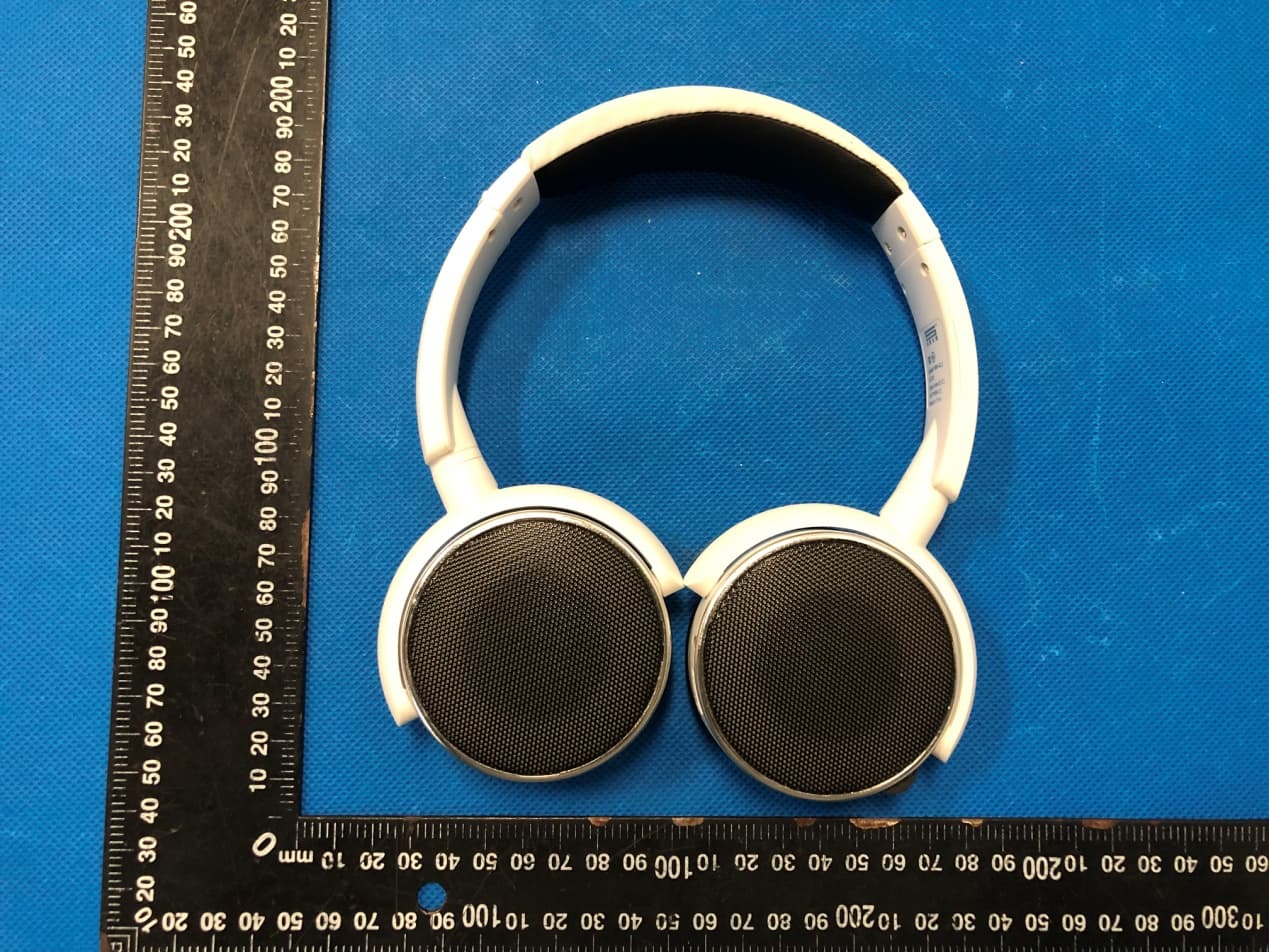
2AZJ2-WM-422
Apr 28, 2022WIRELESS HEADPHONE
Equipment Class
DSS - Part 15 Spread Spectrum Transmitter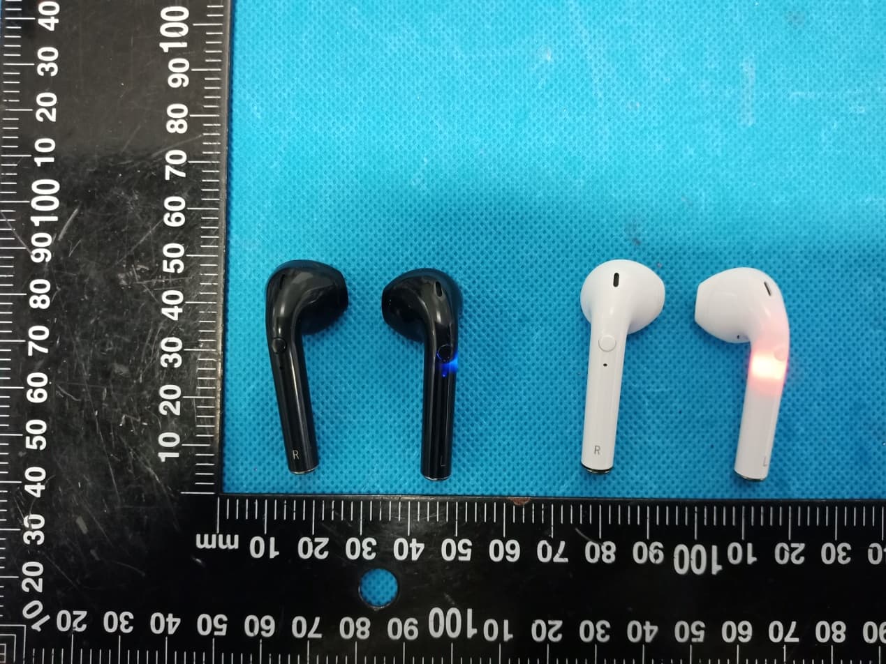
2AZJ2TW004
Jan 19, 2022TWS EARBUDS
Equipment Class
DSS - Part 15 Spread Spectrum Transmitter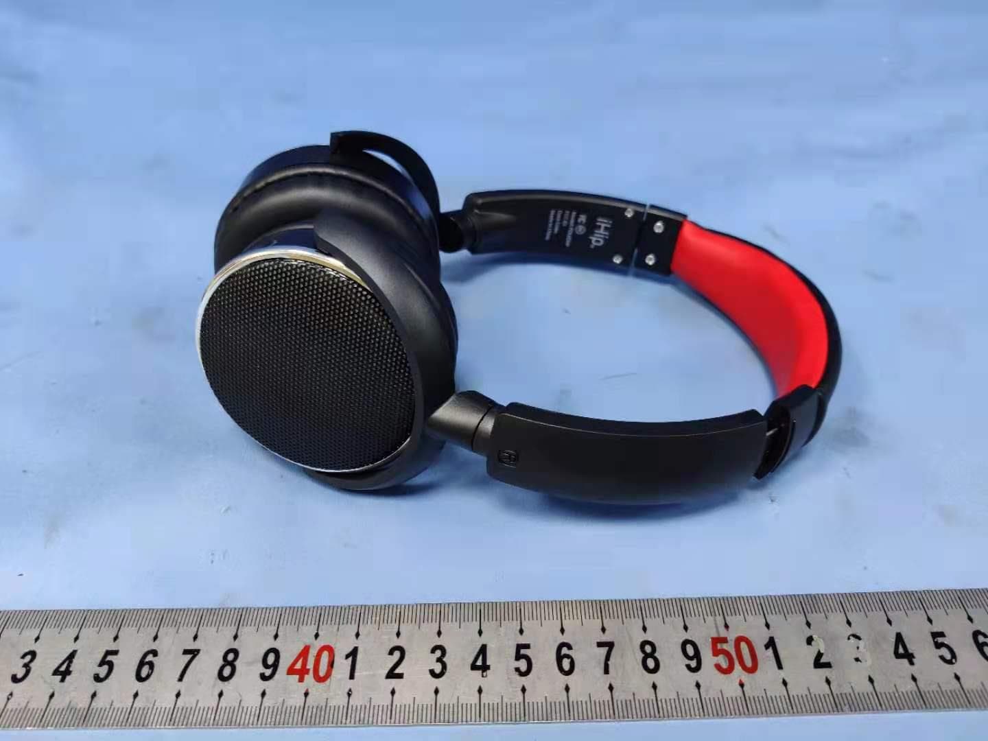
2AZJ2CK105
Jun 05, 2021WIRELESS HEADPHONE
Equipment Class
DSS - Part 15 Spread Spectrum Transmitter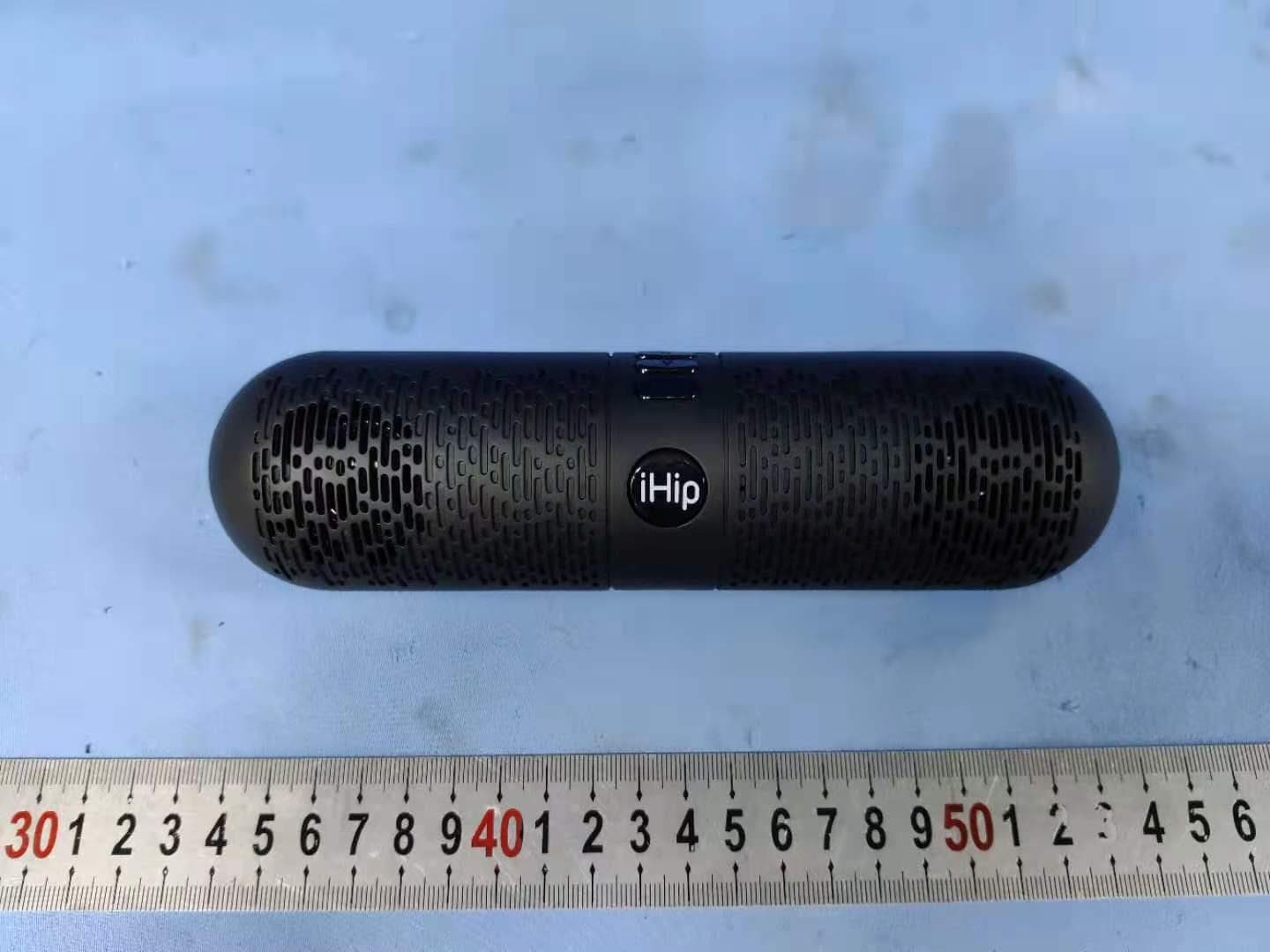
2AZJ2805
May 31, 2021WIRELESS SPEAKER
Equipment Class
DSS - Part 15 Spread Spectrum Transmitter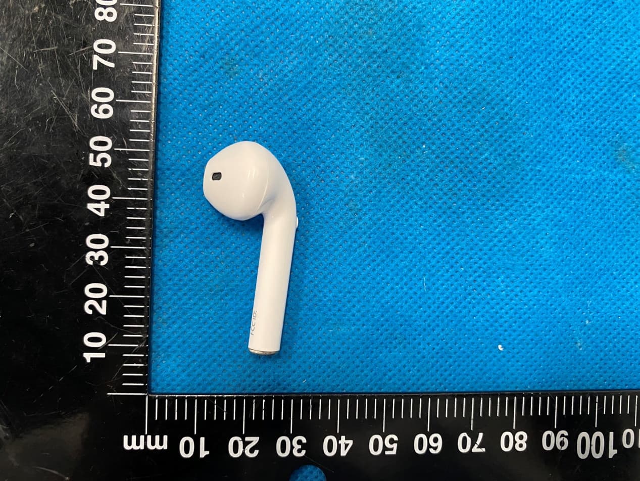
2AZJ2I9S
Apr 14, 2021SoundPods
Equipment Class
DSS - Part 15 Spread Spectrum Transmitter