2AZJC-FARALLONFarallon Smart Buoy
Blue Ocean Gear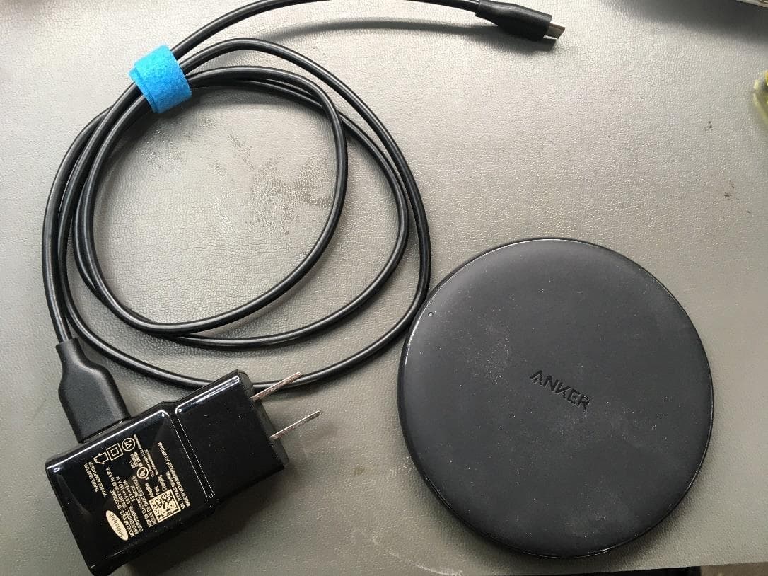
Click to zoom
Application Details
- Equipment Class
- DTS - Digital Transmission System
- Date of Grant
- Aug 25, 2021
- Application Purpose
- Original Equipment
- Date of Application
- Aug 25, 2021
- Equipment Note
- Farallon Smart Buoy
- Frequency Range
- 915.00000000 - 915.00000000
- Company
- Blue Ocean Gear
- Country
- United States
Documents & Files
Document Text
Text extracted from the exhibit documents filed with the FCC. Open a document above to read the original.
Users Manual
©2021 Blue Ocean Gear, Inc. Rev 0.24 – April 2021 FARALLON SMART BUOY SYSTEM™ MANUAL Blue Ocean Gear, Inc. Proprietary ©2021 Blue Ocean Gear, Inc. Page 2 of 15 Farallon Smart Buoy System™ Manual Rev 0.24 – April 2021 Table of Contents DIAGRAM OF A FARALLON SMART BUOY™ .....................................................................................................3 FARALLON SMART BUOY STORAGE.................................................................................................................4 FARALLON SMART BUOY DEPLOYMENT ..........................................................................................................4 BUOY TO GEAR ATTACHMENT ...............................................................................................................................4 FIRST TIME USE .................................................................................................................................................5 FARALLON SMART BUOY COMPONENTS .........................................................................................................5 SENSORS ..........................................................................................................................................................5 GPS ..............................................................................................................................................................................5 DEPTH SENSOR ...............................................................................................................................................................5 SALTWATER SENSOR ........................................................................................................................................................5 COMMUNICATIONS .........................................................................................................................................................5 BASIC FUNCTIONALITY AND PERFORMANCE ..............................................................................................................5 BUOY LOCATOR MAPS AND DATA ..................................................................................................................7 WEBSITE ..........................................................................................................................................................7 BUOY IDENTIFIERS: .............................................................................................................................................7 MAP DISPLAY ...................................................................................................................................................7 CHARTS ...........................................................................................................................................................9 MOBILE APPLICATION FOR IPHONE DEVICES: .......................................................................................................... 10 BLUE OCEAN GEAR CONTACT INFORMATION .......................................................................................................... 14 FCC: ............................................................................................................................................................. 14 ISED: ............................................................................................................................................................ 15 ©2021 Blue Ocean Gear, Inc. Page 3 of 15 Farallon Smart Buoy System™ Manual Rev 0.24 – April 2021 Diagram of a Farallon Smart Buoy™ Top Half of Smart Buoy Bottom Half of Smart Buoy Buoy Parts: 1. Marine seal covering * 2. Attachment ring(s) 3. Vacuum port 4. Depth sensor port 5. Saltwater sensor probes 6. Buoy ID *WARNING: Do not attempt to open the buoy or damage or remove the marine seal covering or seal material between the two halves of the buoy. This will compromise the integrity of the water-tight seal. Do not remove the vacuum port screw or the saltwater sensor probe screws. 3 4 2 1 5 ©2021 Blue Ocean Gear, Inc. Page 4 of 15 Farallon Smart Buoy System™ Manual Rev 0.24 – April 2021 Farallon Smart Buoy Storage Indoor storage of Smart Buoys is recommended prior to deployment, as low temperatures outside may discharge the battery prematurely. Farallon Smart Buoy Deployment Buoy to Gear Attachment The Smart Buoy should be attached as kicker (trailer) buoy to the main buoy of the gear using 2-3 meters of 5/16” line. Tie off the line with your preferred knot to ensure secure attachment (see figures below). IMPORTANT: The line should be threaded through BOTH attachment rings, with the knot positioned to the lower edge of the black tape, as shown in the image below. This ensures the buoy floats upright in the current. Attaching to only a single ring will cause the buoy to tip off-center, preventing optimal sensing and reducing communication capability. It is also possible to loop and splice line through each ring and knot together, as opposed to running around the full circumference of the buoy. Knot/harness below the black centerline of buoy ©2021 Blue Ocean Gear, Inc. Page 5 of 15 Farallon Smart Buoy System™ Manual Rev 0.24 – April 2021 First Time Use The Smart Buoy may be shipped with the saltwater sensor covered with tape. Remove the tape before deploying the buoy. Do not remove the screws underneath. Farallon Smart Buoy Components Sensors GPS The Smart Buoy is equipped with an internal GPS receiver to provide location information. Depth Sensor The Smart Buoy is equipped with a depth sensor to provide information regarding buoy submergence. Saltwater Sensor The saltwater sensor allows the buoy to turn on when it detects that it is in salt water. The buoy will turn on when it has been in water for at least 15 minutes and will turn itself off when it has been out of the water for at least 5 minutes. To avoid activating the …
Text truncated - open the document above for the full version.
Cover Letter(s)
QA-FR-172-A FCC Confidential Authorization 2021-07-29 FEDERAL COMMUNICATIONS COMMISSIONS Authorization and Evaluation Division 7435 Oakland Mills Road Columbia, MD 21046 Subject: Confidentiality Request regarding application for certification of FCC ID: 2AZJC-FARALLON In accordance with Sections 0.457 and 0.459 of the Commission’s Rules, Blue Ocean Gear hereby requests long-term confidential treatment of information accompanying this application as outlined below: •Block Diagram •Schematics •Operation Description •Internal Photos As well as short-term confidential treatment of information accompanying this application as outlined below: •User’s Manual •External Photos •Test Set-up Photos The above materials contain proprietary and confidential information not customarily released to the public. The public disclosure of these materials provides unjustified benefits to its competitors in the market. Sincerely, Kortney Opshaug, CEO (650) 823-1704 [email protected] 914 Edgecliff Way Redwood City, CA 94061-1160
Cover Letter(s)
QA-FR-170-B 7/29/2014 Declaration Letter 2021-07-29 To: FEDERAL COMMUNICATIONS COMMISSIONS Authorization and Evaluation Division 7435 Oakland Mills Road Columbia, MD 21046 Dear Sir or Madam: We, Blue Ocean Gear, hereby confirmed the product: Farallon Smart Buoy, Model: Farallon, FCC ID: 2AZJC-FARALLON, due to proprietary design and patentable rights granted, we request to list internal photographs under long-term confidential treatment, and not to be public. Shall you have any question or concern, please contact in with me directly. Sincerely Yours, Kortney Opshaug, CEO (650) 823-1704 [email protected] 914 Edgecliff Way Redwood City, CA 94061-1160
Cover Letter(s)
1 MUTUAL NONDISCLOSURE AGREEMENT THIS MUTUAL NONDISCLOSURE AGREEMENT (the "Agreement") is entered into as of _______________ (the “Effective Date”) between Blue Ocean Gear Inc, a California company with its principal offices at 914 Edgecliff Way, Redwood City, CA, USA 94061, and ________________________. (Individual/Company) IT IS AGREED, in consideration of the covenants contained herein, as follows: 1. Each party (the "Disclosing Party," as applicable) will disclose to the other party (the "Recipient," as applicable) certain of the Disclosing Party’s confidential and proprietary information, software, hardware, equipment, or other materials (collectively, "Confidential Information", regardless of whether marked as “Confidential”), which Confidential Information may include, without limitation, marketing plans, research and development memoranda, data, prototypes, designs, software, technical information and other information containing trade secrets and know-how, intellectual property and financial and business information, and which Confidential Information may be disclosed in writing, verbally, electronically, graphically, or by inspection of tangible objects. The Disclosing Party’s Confidential Information will also include: (i) any and all information disclosed hereunder that, under the circumstances, a person exercising reasonable business judgment would deem it to be confidential or proprietary and (ii) all discoveries, experimental results, data, reports, papers, notebook entries, and memoranda comprising or incorporating, in whole or in part, its Confidential Information or items derived therefrom or based thereon. 2. Recipient will maintain all Confidential Information disclosed hereunder by the Disclosing Party in confidence and will not use, publish, describe or exploit such Information or disclose such Information to any third party other than those of its employees, contractors, consultants, or advisors with a demonstrable need to know such Information; provided that each such employee must execute or have executed an agreement under which he or she is fully bound by the obligations of Recipient hereunder. For the avoidance of doubt, Recipient will not disclose the Disclosing Party’s Confidential Information to its parent, its subsidiaries or any other affiliates. Recipient will use the same degree of care to protect the Disclosing Party’s Confidential Information as Recipient uses to protect its own most highly confidential information. Recipient will be liable and responsible for any breach of this Agreement by any of its employees. Recipient will not use or exploit the Confidential Information except as necessary to explore a potential business relationship with the Disclosing Party or, if entered into by the parties, to engage in that business relationship with the Disclosing Party. Except as expressly permitted by the Disclosing Party in writing, Recipient will not (i) reverse engineer, disassemble, or decompile any software, equipment, or other tangible or intangible objects that embody or incorporate the Disclosing Party’s Confidential Information or (ii) make any copies of the Disclosing Party’s Confidential Information. Recipient will not incorporate or otherwise use the Disclosing Party’s Confidential Information in connection with any patent application. Recipient will mark any and all approved copies as Confidential Information and retain the Disclosing Party’s proprietary notices, and immediately notify the Disclosing Party of any unauthorized use, loss, or disclosure of the Disclosing Party’s Confidential Information. 3. This Agreement will not apply to any Confidential Information that (i) is already lawfully in Recipient's possession, (ii) becomes generally available to the public through no fault or breach of Recipient or breach by a third party of any obligation of confidentiality owed to the Disclosing Party, (iii) is disclosed to Recipient by a third party who may transfer or disclose such Information without restriction of any kind, (iv) is required to be disclosed by Recipient as a matter of law or judicial or governmental mandate; provided that 2 Recipient will use all reasonable efforts to provide the Disclosing Party with an opportunity to appear and object to such disclosure, (v) is disclosed by Recipient with the Disclosing Party's approval or (vi) is independently developed by Recipient without any use of the Disclosing Party’s Confidential Information as evidenced by the Recipient’s records. 4. The Disclosing Party warrants that it has the right to disclose the Confidential Information to Recipient. The Confidential Information disclosed hereunder remains the property of the Disclosing Party and no license or other rights in or to such Information, expressly including rights or licenses in or to any of the Disclosing Party’s trade secrets, copyrights or patents, is granted to Recipient hereby. THE CONFIDENTIAL INFORMATION DISCLOSED HEREUNDER IS PROVIDED "AS IS" AND THE DISCLOSING PARTY MAKES NO REPRESENTATION OR WARRANTY AS TO THE ACCURACY OR COMPLETENESS THEREOF. 5. Recipient acknowledges that the Disclosing Party will suffer irreparable harm on any unauthorized disclosure of Confidential Information by Recipient. Accordingly, on any breach hereof by Recipient, the Disclosing Party will be entitled to immediately obtain equitable relief, including injunctive relief, in addition to any other remedies it may have by law or in equity. 6. The parties are entering into this Agreement as independent parties and nothing herein will be deemed to create any employer/employee, principal/agent, joint venture or other relationship between the parties hereto. 7. This Agreement is effective as of the Effective Date and will continue until the earlier of: (i) such time as all Confidential Information disclosed under this agreement becomes publicly known and is made generally available through no action or inaction of the Receiving Party or (ii) the first ann…
Text truncated - open the document above for the full version.
External Photos
Blue Ocean Gear FCC ID: 2AZJC-FARALLON; IC: 27151-FARALLON Annex B (Normative) - EUT External Photographs 1.1 EUT Top View 1.2 EUT Bottom View Blue Ocean Gear FCC ID: 2AZJC-FARALLON; IC: 27151-FARALLON 1.3 EUT Front View 1.4 EUT Rear View Blue Ocean Gear FCC ID: 2AZJC-FARALLON; IC: 27151-FARALLON 1.5 EUT Support Equipment (Charger)
ID Label/Location Info
Label & Label Location
RF Exposure Info
Blue Ocean Gear FCC ID: 2AZJC-FARALLON; IC: 27151-FARALLON Report Number: R2103262-247 Page 13 of 38 FCC Part 15C/ISEDC RSS-247 Test Report 5 FCC §2.1091, §15.247(i) & ISEDC RSS-102 - RF Exposure 5.1 Applicable Standards According to FCC §15.247(i) and §1.1307(b)(1), systems operating under the provisions of this section shall be operated in a manner that ensures that the public is not exposed to radio frequency energy level in excess of the Commission’s guidelines. Limits for General Population/Uncontrolled Exposure Frequency Range (MHz) Electric Field Strength (V/m) Magnetic Field Strength (A/m) Power Density (mW/cm 2 ) Averaging Time (minutes) Limits for General Population/Uncontrolled Exposure 0.3-1.34 614 1.63 * (100) 30 1.34-30 824/f 2.19/f * (180/f 2 ) 30 30-300 27.5 0.073 0.2 30 300-1500 / / f/1500 30 1500-100,000 / / 1.0 30 f = frequency in MHz * = Plane-wave equivalent power density According to ISED RSS-102 Issue 5: Blue Ocean Gear FCC ID: 2AZJC-FARALLON; IC: 27151-FARALLON Report Number: R2103262-247 Page 14 of 38 FCC Part 15C/ISEDC RSS-247 Test Report 5.2 MPE Prediction Predication of MPE limit at a given distance, Equation from OET Bulletin 65, Edition 97-01 S = PG/4SR² Where: S = power density P = power input to antenna G = power gain of the antenna in the direction of interest relative to an isotropic radiator R = distance to the center of radiation of the antenna 5.3 MPE Results Maximum output power at antenna input terminal (dBm): 17.81 Maximum output power at antenna input terminal (mW): 60.39 Prediction distance (cm): 20 Prediction frequency (MHz): 915 Maximum Antenna Gain, typical (dBi): 2.4 Maximum Antenna Gain (numeric): 1.74 Power density of prediction frequency at 20.0 cm (mW/cm 2 ): 0.021 FCC MPE limit for uncontrolled exposure at prediction frequency (mW/cm 2 ): 0.61 The device is compliant with the requirement MPE limit for uncontrolled exposure. The maximum power density at the distance of 20 cm is 0.021 mW/cm 2 . Limit is 0.61 mW/cm 2 . 5.4 RF exposure evaluation exemption for IC Maximum EIRP power = 17.81 dBm + 2.4 dBi = 20.21 dBm which is lesser than 1.31×10 -2 f 0.6834 = 1.3839 W = 31.41 dBm. Therefore, the RF exposure Evaluation is exempt. Note: Device also has approved radio module operating in 1626.5 MHz frequency range. However, the two radios cannot co-locate.
Test Report
Note: This test report is prepared for the customer shown above and for the device described herein. It may not be duplicated or used in part without prior written consent from Bay Area Compliance Laboratories Corp. This report must not be used by the customer to claim product certification, approval, or endorsement by A2LA*, NIST, or any agency of the Federal Government. * This report may contain data that are not covered by the A2LA accreditation and are marked with an asterisk “*” (Rev.2) FCC PART 15, SUBPART C ISEDC RSS-247, ISSUE 2, FEBRUARY 2017 TEST AND MEASUREMENT REPORT For Blue Ocean Gear 914 Edgecliff Way, Redwood City, CA 94061, USA FCC ID: 2AZJC-FARALLON IC: 27151-FARALLON R e p o r t T y p e : O r i gi n a l R e p o r t P r o d u c t T y p e: S ma r t B u oy Prepared By: Christian McCaig RF Project Engineer Report Number: R2103262-247 Report Date: 2021-08-26 Reviewed By: Simon Ma RF Supervisor Bay Area Compliance Laboratories Corp. 1274 Anvilwood Avenue, Sunnyvale, CA 94089, USA Tel: +1 (408) 732-9162, Fax: +1 (408) 732-9164 Blue Ocean Gear FCC ID: 2AZJC-FARALLON; IC: 27151-FARALLON Report Number: R2103262-247 Page 2 of 38 FCC Part 15C/ISEDC RSS-247 Test Report TABLE OF CONTENTS 1 General Description ..................................................................................................................................................... 5 1.1 Product Description for Equipment Under Test (EUT) ...................................................................................... 5 1.2 Mechanical Description of EUT ......................................................................................................................... 5 1.3 Objective ............................................................................................................................................................. 5 1.4 Related Submittal(s)/Grant(s) ............................................................................................................................. 5 1.5 Test Methodology ............................................................................................................................................... 5 1.6 Measurement Uncertainty ................................................................................................................................... 6 1.7 Test Facility Registrations .................................................................................................................................. 6 1.8 Test Facility Accreditations ................................................................................................................................ 7 2 System Test Configuration.......................................................................................................................................... 9 2.1 Justification ......................................................................................................................................................... 9 2.2 EUT Exercise Software....................................................................................................................................... 9 2.3 Duty Cycle Correction Factor ............................................................................................................................. 9 2.4 Equipment Modifications.................................................................................................................................. 10 2.5 Local Support Equipment ................................................................................................................................. 10 2.6 Remote Support Equipment .............................................................................................................................. 10 2.7 Interface Ports and Cabling ............................................................................................................................... 10 3 Summary of Test Results ............................................................................................................................................ 11 4 FCC §15.203 & ISEDC RSS-Gen §6.8 - Antenna Requirements ............................................................................ 12 4.1 Applicable Standards ........................................................................................................................................ 12 4.2 Antenna Description ......................................................................................................................................... 12 5 FCC §2.1091, §15.247(i) & ISEDC RSS-102 - RF Exposure .................................................................................... 13 5.1 Applicable Standards ........................................................................................................................................ 13 5.2 MPE Prediction ................................................................................................................................................. 14 5.3 MPE Results ..................................................................................................................................................... 14 5.4 RF exposure evaluation exemption for IC ........................................................................................................ 14 6 FCC §15.207 & ISEDC RSS-Gen §8.8 - AC Line Conducted Emissions ................................................................ 15 6.1 Applicable Standards ........................................................................................................................................ 15 6.2 Test Setup ......................................................................................................................................................... 15 6.3 Test Procedure ...................................................................................…
Text truncated - open the document above for the full version.
Test Setup Photos
Blue Ocean Gear FCC ID: 2AZJC-FARALLON; IC: 27151-FARALLON EUT Test Setup Photographs 1.1 Below 1 GHz Front View 1.2 Below 1 GHz Rear View Blue Ocean Gear FCC ID: 2AZJC-FARALLON; IC: 27151-FARALLON 1.3 Above 1 GHz at 3 Meters Front View 1.4 Above 1 GHz at 3 Meters Rear View Blue Ocean Gear FCC ID: 2AZJC-FARALLON; IC: 27151-FARALLON 1.5 Above 1 GHz at 1 Meter Front View 1.6 Above 1 GHz at 1 Meter Rear View Blue Ocean Gear FCC ID: 2AZJC-FARALLON; IC: 27151-FARALLON 1.7 AC Line Test Front View 1.8 AC Line Test Side View
Contact Information
Applicant
Kortney Opshaug
Test Firm
Bay Area Compliance Laboratories Corp.Lisa Tang
Technical Specifications
| # | Rule Parts | Frequency Range | Power Output |
|---|---|---|---|
| 1 | 15C | 915 MHz - 915 MHz | 60.00 mW |