2AZKWREBE-TZ29CElectronic Shelf Label
ATEC IOT CO.LTD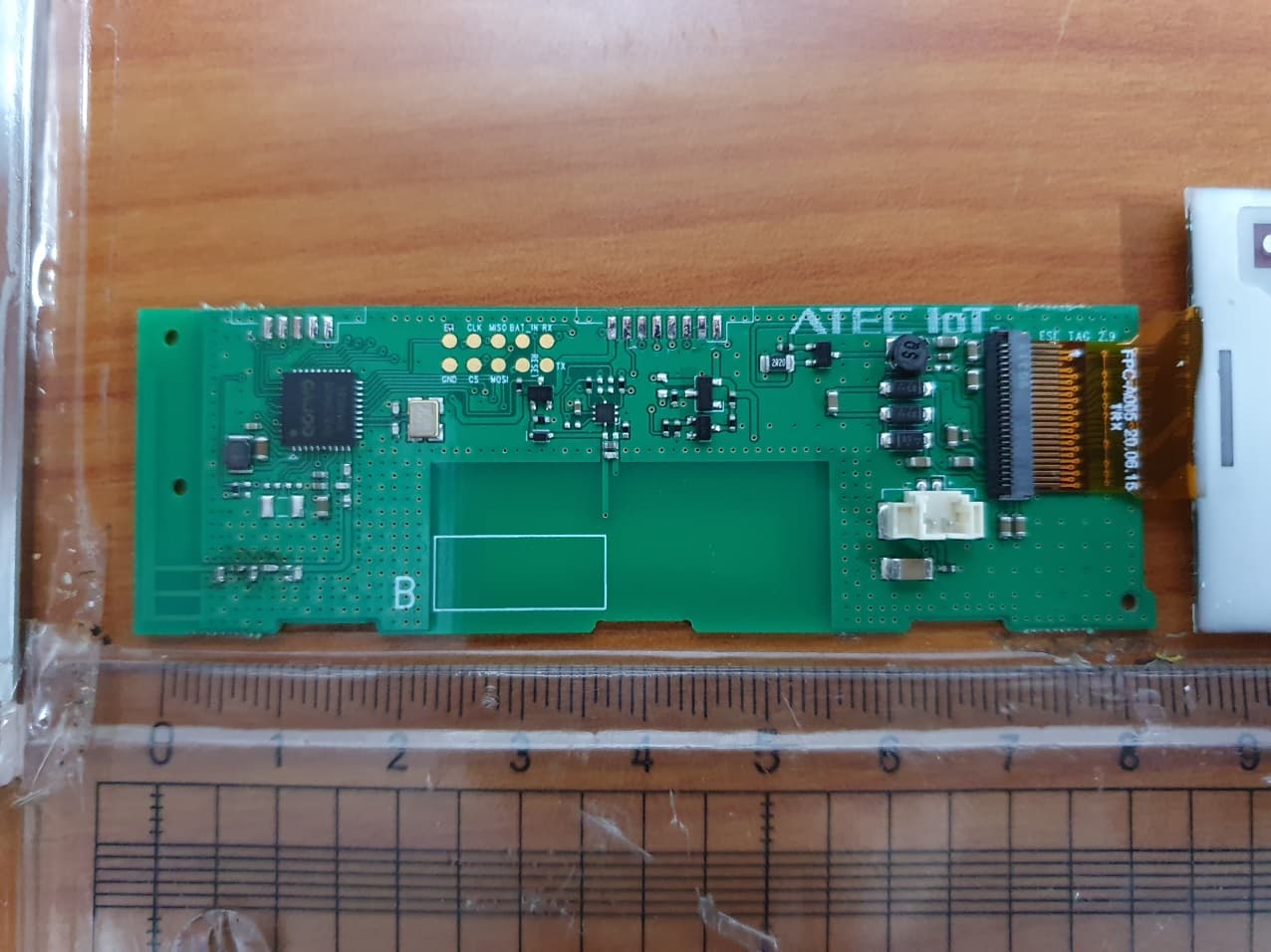
Click to zoom
Application Details
- Equipment Class
- DTS - Digital Transmission System
- Date of Grant
- Jul 26, 2021
- Application Purpose
- Original Equipment
- Date of Application
- Jul 26, 2021
- Equipment Note
- Electronic Shelf Label
- Frequency Range
- 2405.00000000 - 2480.00000000
- Company
- ATEC IOT CO.LTD
- Country
- South Korea
Documents & Files
Document Text
Text extracted from the exhibit documents filed with the FCC. Open a document above to read the original.
Users Manual
CUSTOMER : Standard DATE : 2020. 06. 22 REV : Rev. 1.0 SPECIFICATIONS FOR APPROVAL RoHS Compliant REBE-TZ29C Model Part Number Customer P/N 2.9” 3-Color Graphic LED REBE-TZ29C - APPROVAL REMARK APPENDIX DESIGNED CHECKED APPROVED 2020.06.19 2020.06.19 2020.06.22 K.S.AN H.H.HAN I.U.KIM 1 / 21 Revision History SPECIFICATION MODEL REBE-TZ29C REV. No. Rev. 1.0 REG. DATE 2020.06.22 PAGE 21 REV. DATE 2020.06.22 - - Revision Date Contents of Revision Change Remark 1.0 ’20.06.22 First release H.H.Han 2 / 21 TABLE OF CONTENTS 1. Application∙∙∙∙∙∙∙∙∙∙∙∙∙∙∙∙∙∙∙∙∙∙∙∙∙∙∙∙∙∙∙∙ 3/21 2. Quality∙∙∙∙∙∙∙∙∙∙∙∙∙∙∙∙∙∙∙∙∙∙∙∙∙∙∙∙∙∙∙∙ 3/21 3. Appearance and Characteristics∙∙∙∙∙∙∙∙∙∙∙∙∙∙∙∙∙∙∙∙∙∙∙∙∙∙∙∙∙∙∙∙ 3/21 4. Overall Service Scenario ∙∙∙∙∙∙∙∙∙∙∙∙∙∙∙∙∙∙∙∙∙∙∙∙∙∙∙∙∙∙∙∙ 4/21 5. General Features∙∙∙∙∙∙∙∙∙∙∙∙∙∙∙∙∙∙∙∙∙∙∙∙∙∙∙∙∙∙∙∙ 5/21 6. Absolute Maximum Rating∙∙∙∙∙∙∙∙∙∙∙∙∙∙∙∙∙∙∙∙∙∙∙∙∙∙∙∙∙∙∙∙ 7/21 7. Electrical Specification∙∙∙∙∙∙∙∙∙∙∙∙∙∙∙∙∙∙∙∙∙∙∙∙∙∙∙∙∙∙∙∙ 8/21 8. Mechanical Information∙∙∙∙∙∙∙∙∙∙∙∙∙∙∙∙∙∙∙∙∙∙∙∙∙∙∙∙∙∙∙∙ 9/21 9. Packaging ∙∙∙∙∙∙∙∙∙∙∙∙∙∙∙∙∙∙∙∙∙∙∙∙∙∙∙∙∙∙∙∙ 13/21 10. User Quick Manual ∙∙∙∙∙∙∙∙∙∙∙∙∙∙∙∙∙∙∙∙∙∙∙∙∙∙∙∙∙∙∙∙ 16/21 11. RoHS Compliance ∙∙∙∙∙∙∙∙∙∙∙∙∙∙∙∙∙∙∙∙∙∙∙∙∙∙∙∙∙∙∙∙ 18/21 12.Related Certification ∙∙∙∙∙∙∙∙∙∙∙∙∙∙∙∙∙∙∙∙∙∙∙∙∙∙∙∙∙∙∙∙ 19/ 21 13. Disclaimers ∙∙∙∙∙∙∙∙∙∙∙∙∙∙∙∙∙∙∙∙∙∙∙∙∙∙∙∙∙∙∙∙ 20/ 21 14. Ordering Information ∙∙∙∙∙∙∙∙∙∙∙∙∙∙∙∙∙∙∙∙∙∙∙∙∙∙∙∙∙∙∙∙ 21/ 21 3 / 21 1. Application This Specification is applied to ATEC IOT Wireless Electronic Shelf Label. (REBE-TZ29C) REBE-TZ29C is used by retailers for displaying product pricing on shelves. Typically, electronic display modules are attached to the front edge of retail shelving. These modules use Electrophoretic Display (EPD) or similar screen technologies to show the current product price to the customer. A communication network allows the price display to be automatically updated whenever a product price is changed. 2. Quality Quality should meet each condition which mentioned on this specification. However, the items which are not mentioned on this specification follow the inspection agreements and standards which are agree with both companies. 3. Appearance and Characteristics Appearance should not be contaminated by harmful materials and should not have cracks, etc. Mechanical dimensions should meet the contents of clause 9. 3.1. Appearance Electrical Characteristics should meet the contents of clause 7. 3.2. Characteristic 4 / 21 4. Overall Service Scenario • One Platform & Integrated Gateway Wired • WiFi / Ethernet • IEEE802.15.4 • 2,000 Tags per GW ESL EMS (1) Server POS (1) EMS : ESL Management Software GATEWAY 2.4GHz Wireless Tags (Battery / Power Line) Wireless & Bi-Directional 5 / 21 5. General Features 5.1. Description Item Description Size 90.3 x 42.3 x 12.5 mm Weight Typ. 48.8g (Include Battery - Battery 13.5g) Digital Display Type : Electrophoretic Display Size / DPI : 66.9(H) x 29.06(V) (mm) / 112 Display Color 3- Color (Red/Black/White) (1) Indicator Color 3- Color (Red/Green/Blue) (2) Power Rate : 3.0 V / 100 mA CR2450 Coin Battery 2in1 PKG* 1 set (Removable) Battery Capacity : Max. 1,100 mAh Battery life time: 5 year at 23°C and 55% RH (3) (Image update 2 times per day) NFC Operating frequency of 13.56 MHz Network 802.15.4 2.4GHz IEEE802.15.4 compliant RF Transceiver Security Robust wireless network (ATEC IOT own protocol) Protocol Compatible with ATEC IOT protocol communication devices Comm. Range Max. 30m (Under LoS) (4)(5) [Notice] (1) If the background of display is red, display quality can be decreased. Generally, we recommend that the portion of red color has less than 50%. (2) The LED luminous intensity depends on operating voltage. (3) The battery life time depends on operating conditions (Temperature, humidity, wireless environment, image update count, Indicator...etc) (4) LoS (Line of Sight) : Without any sort of an obstacle between a gateway and end devices. (5) Communication Range depends on surrounding environment. 7 / 21 6. Absolute Maximum Rating 6.1. Environmental Conditions The normal operating environmental conditions are those as below. In such conditions, ESL must be in conformity with the present specification. The conformity to such requirement must be certified by the manufacturer. Parameter Condition Min. Typ. Max. Unit Operating Environment Temperature 10 23 30 °C Humidity 45 55 65 %RH Storage Environment Temperature 0 23 40 °C Humidity 45 55 65 %RH 6.2. Electrical Conditions The operating electrical conditions are those as below. In such conditions the ESL must be in conformity with the present specification. All devices can be damaged or non-operated over the specification as below. The conformity to such requirement must be certified by the manufacturer. Parameter Condition Min Typ. Max Unit Supply Voltage DC Power Supply 2.3 3.0 3.3 V Power Consumption @ 3.0~3.3V - - 100 mA ESD Protection Air Condition @Soft Fail -8 - +8 kV (1) Tag can operate at 0~40°C. But only assure the image quality of EPD at 10~30°C. (2) Depending on the characteristic of the EPD, it may become reddish by passing time. (3) Moisture and liquid can damage the tag and reduce its life time. (4) Getting a magnetic close to the tag can be degraded the performance. ( w ireless communication, remote controller, etc) (5) When storing the tag, change it to a white screen, and maintain the proper tem perature and humidity. (6) After receiving the product, it should be installed within 3 months. (7) The display glass may break when it is dropped or bumped on a hard surface. (f ragile by external impact) [Notice] 8 / 21 7. Electrical Specification 7.1. IEEE802.15.4 The REBE-TZ29C supports IEEE802.15.4. 7.2. General Specification • Standard : Only IEEE802.15.4 PHY • Frequency : 2405 ~ 2480MHz • Channel : 16CH. (5MHz Spacing) • Modulation : DSSS/O-QPSK • Max . Data Rate : 250Kbps 7.3. Electrical Specification • Channel power depend on each country regulations (EX. KC, etc) • The electrical specification which is shown below is ATEC IOT internal spe…
Text truncated - open the document above for the full version.
Attestation Statements
ATEC IoT CO., LTD. 289, Pangyo-ro, Bundang-gu, Seongnam-si, Gyeonggi-do, Republic of Korea June 25, 2021 Federal Communications Commission Equipment Authorization Branch 7435 Oakland Mills Road Columbia, MD 21046 In re : ATEC IoT CO., LTD. FCC Application for FCC ID : 2AZKWREBE-TZ29C To whom it may concern: We, the undersigned, hereby attest to the fact that we will apply the Supplier’s Declaration of Conformity procedure to the class B computer peripheral portion of this composite filing. Regards, Sincerely, In Uk Kim / CEO ATEC IoT CO., LTD.
Cover Letter(s)
ATEC IoT CO., LTD. 289, Pangyo-ro, Bundang-gu, Seongnam-si, Gyeonggi-do, Republic of Korea June 25, 2021 Federal Communications Commission Equipment Authorization Branch 7435 Oakland Mills Road Columbia, MD 21046 In re : ATEC IoT CO., LTD. FCC ID : 2AZKWREBE-TZ29C Request for Confidentiality Pursuant to Sections 0.457 and 0.459 of the Commission’s Rules (CFR 47), ATEC IoT CO., LTD. hereby requests confidentiality and treatment of certain information accompanying this application. The materials contain trade secrets and proprietary information not customarily released to the public. The public disclosure of these matters might be harmful to the Applicant and provide unjustified benefits to its competitors. We are also hereby request Short-Term Confidentiality for 180 days after the grant as outlined in Public Notice DA 04-1705. This provision will give ATEC IoT CO., LTD. temporary confidentiality of commercially sensitive information prior to product release. The requested Confidential and Temporary Confidential exhibits are listed as follows: Exhibit Type File Name CONFIDENTIAL Schematics CONF APPENDIX 2AZKWREBE-TZ29C SCH DIA.pdf Parts list CONF APPENDIX 2AZKWREBE-TZ29C PL.pdf Block diagram CONF APPENDIX 2AZKWREBE-TZ29C BLK DIA.pdf Operational description CONF APPENDIX 2AZKWREBE-TZ29C OpDes.pdf SHORT-TERM CONFIDENTIAL External Photos SHORT-TERM CONF 2AZKWREBE-TZ29C EXT Photo.pdf Internal Photos SHORT-TERM CONF 2AZKWREBE-TZ29C INT Photo.pdf Te s t-Setup Photos SHORT-TERM CONF 2AZKWREBE-TZ29C Test Photo.pdf User’s Manual SHORT-TERM CONF 2AZKWREBE-TZ29C Manual.pdf The Applicant understands that pursuant to Rule 0.457, disclosure of this application and all accompanying documentations, where applicable, will not be made public before the date of the Grant for this application. Sincerely, In Uk Kim / CEO ATEC IoT CO., LTD.
ID Label/Location Info
FCC ID: 2AZKWREBE-TZ29C SAMPLE LABEL & LOCATION REAR ATEC IoT CO., LTD. Model : REBE-TZ29C Rated Voltage : 3 V FCC ID : 2AZKWREBE-TZ29C Made in Korea Copyright Ⓒ 2021, LTA Co., Ltd.
Internal Photos
FCC ID: 2AZKWREBE-TZ29C MainBoard–Front MainBoard–Rear Copyright ○ c 2021, LTA Co., Ltd. Page 1 of 2 FCC ID: 2AZKWREBE-TZ29C Internal Copyright ○ c 2021, LTA Co., Ltd. Page 2 of 2
RF Exposure Info
FCC ID: 2AZKWREBE-TZ29C ATTACHMENT RF EXPOSURE EVULATION 1.1 Limit According to §1.1310 and §2.1091 RF exposure is calculated. (B) Limits for General Population/Uncontrolled Exposures Frequency range (MHz) Electric field Strength Magnetic field Strength Power density Averaging time 1.34 - 30....................................... 824/f 2.19/f *(180/ f²) 30 30 - 300....................................... 27.5 0.073 0.2 30 300 - 1500.................................... ............... ............... f/1500 30 1500 - 100.000................................. ............... ............... 1.0 30 F = frequency in MHz * = Plane-wave equivalent power density 1.2 MAXIMUM PERMISSIBLE EXPOSURE Prediction Prediction of MPE limit at a given distance Power density at the specific separation: S = PG/(4R 2 π) Where, S = Maximum power density (mW/cm 2 ) P = Power input to the antenna (mW) G = Numeric power gain of the antenna R = Distance to the center of the radiation of the antenna (20 cm = limit for MPE) S = (1.63 * 0.34) / (4 * 20 2 * π) S = 0.0001 mW/cm 2 FCC ID: 2AZKWREBE-TZ29C ATTACHMENT 1.3 MAXIMUM PERMISSIBLE EXPOSURE Prediction - Calculated under the worst-case conditions of each mode. (Measured power 0.9 dBm ± 0.5dB) 3-1. 2.4 GHz Mode Max Peak output Power at antenna input terminal 2.18 dBm Max Peak output Power at antenna input terminal 1.65 mW Prediction distance 5 mm Prediction frequency 2,480 MHz Antenna Gain(typical) -4.67 dBi Antenna Gain(numeric) 0.34 - For 100 MHz to 6 GHz and test separation distances ≤ 50 mm, the 1-g and 10-g SAR test exclusion thresholds are determined by the following: [(max. power of channel, including tune-up tolerance, mW) / (min. test separation distance, mm)] ·[√f(GHz)] ≤ 3.0 for 1-g SAR, and ≤ 7.5 for 10-g extremity SAR [(1.23)/(5)] ·[√2.480] = 0.520 ≤ 3.0 Thus, SAR for this device is not required.
Test Report
Ref. No.: LR500112107F 243 Jubug-Ri,Yangji-Myeon, Yongin-Si, Gyeonggi-Do, Korea 17159 Tel: +82-31-323-6008 Fax: +82-31-323-6010 http://www.ltalab.com Dates of Tests: June 17, 2021 ~ July 14, 2021 Test Report S/N: LR500112107F Test Site : LTA CO., LTD. CERTIFICATION OF COMPLIANCE FCC ID. APPLICANT Equipment Class : Digital Transmission System (DTS) Manufacturing Description : Electronic Shelf Label Manufacturer : SUZHOU NIHONE Electronics Technology Co., LTD. Model name : REBE-TZ29C Test Device Serial No.: : Identical prototype Rule Part(s) : FCC Part 15.247 Subpart C ; ANSI C63.10 - 2013 Frequency Range : Zigbee 2405 ~ 2480 MHz Max. Output Power : Max 2.18 dBm - Conducted Data of issue : July 15, 2021 This test report is issued under the authority of: The test was supervised by: Ja -Beom Koo, Manager Jae-Huem, Yun, Test Engineer This test result only responds to the tested sample. It is not allowed to copy this report even partly without the allow ance of the test laboratory. The report must not be used by the client to claim product certification, approval, or endorsement by NVLAP, NIST, or any agency of the Federal Government. NVLAP LAB Code.: 200723-0 2AZKWREBE-TZ29C ATEC IoT CO., LTD. Copyright ○ c 2021, LTA Co., Ltd. Page 1 of 33 Ref. No.: LR500112107F TAZigbee OF CONTENTS 1. GENERAL INFORMATION -------------------------------------------------------------------------- 2. INFORMATION ABOUT TEST ITEM ------------------------------------------------------------- 3. TEST REPORT ------------------------------------------------------------------------------------------ 3.1 SUMMARY OF TESTS ---------------------------------------------------------------------------- 3.2 TECHNICAL CHARACTERISTICS TEST ----------------- ----------------------------------- 3.2.1 6 dB BANDWIDTH -------------------------------------------------------------------------- 3.2.2 PEAK OUTPUT POWER -------------------------------------------------------------------- 3.2.3 POWER SPECTRAL DENSITY ------------------------------------------------------------ 3.2.4 BAND EDGE ---------------------------------------------------------------------------------- 3.2.5 CONDUCTED SPURIOUS EMISSIONS ------------------------------------------------- 3.2.6 RADIATED SPURIOUS EMISSIONS ---------------------------------------------------- 3.2.7 AC CONDUCTED EMISSIONS ----------------------------------------------------------- APPENDIX APPENDIX TEST EQUIPMENT USED FOR TESTS -------------------------------------------- 3 4 5 5 6 6 9 12 15 17 20 32 33 Copyright ○ c 2021, LTA Co., Ltd. Page 2 of 33 Ref. No.: LR500112107F 1. General information 1-1 Test Performed Company name : LTA Co., Ltd. Address : 243, Jubug-ri,Yangji-Myeon,Youngin-Si, Kyunggi-Do, Korea. 17159 Web site : http://www.ltalab.com E-mail : [email protected] Telephone : +82-31-323-6008 Facsimile +82-31-323-6010 Quality control in the testing laboratory is implemented as per ISO/IEC 17025 which is the “General requirements for the competents of calibration and testing laboratory”. 1-2 Accredited agencies LTA Co., Ltd. is approved to perform EMC testing by the following agencies: Agency Country Accreditation No. Validity Reference NVLAP U.S.A 200723-0 2021-09-30 ECT accredited Lab. RRA KOREA KR0049 - EMC accredited Lab. FCC U.S.A 649054 2023-01-15 FCC CAB VCCI J APA N C-4948, 2023-09-10 VCCI registration VCCI J APA N T-2416, 2023-09-10 VCCI registration VCCI J APA N R-4483(10 m), 2023-08-15 VCCI registration VCCI J APA N G-847 2021-12-13 VCCI registration IC CANADA 5799A-1 2022-10-18 IC filing KOLAS KOREA NO.551 2021-08-20 KOLAS accredited Lab. Copyright ○ c 2021, LTA Co., Ltd. Page 3 of 33 Ref. No.: LR500112107F 2. Information about test item 2-1 Client & Manufacturer Client Company name : ATEC IoT CO., LTD. Address : 289, Pangyo-ro, Bundang-gu, Seongnam-si, Gyeonggi-do, 13488, South Korea Tel / Fax : +82-10-5790-6171 / +82-31-696-1534 Manufacturer SUZHOU NIHONE Electronics Technology Co., LTD Address No. 185,Xiaoxiang Road, Suzhou New District, Suzhou City, Jiangsu Province, P.R. China Tel / Fax +82-10-5790-6171 / +82-31-696-1534 2-2 Equipment Under Test (EUT) Model name : ATEC IoT CO., LTD. Serial number : Identical prototype Date of receipt : June 17, 2021 EUT condition : Pre-production, not damaged Antenna type : FPCB Antenna (Max Gain : - 4.67 dBi) Frequency Range : Zigbee 2405 ~ 2480 MHz RF output power : Max 2.18 dBm – Conducted Type of Modulation : Pi/4 DQPSK, 8DPSK Power Source : DC 3.0 V 2-3 Tested frequency LOW MID HIGH Frequency (MHz) Zigbee 2405 2440 2480 2-4 Ancillary Equipment Equipment Model No. Serial No. Manufacturer Notebook - MS-1736 MSI Copyright ○ c 2021, LTA Co., Ltd. Page 4 of 33 Ref. No.: LR500112107F 3. Test Report 3.1 Summary of tests FCC Part Section(s) Parameter Test Condition Status (note 1) 15.247(a) 6 dB Bandwidth Conducted C 15.247(b) Transmitter Peak Output Power C 15.247(e) Transmitter Power Spectral Density C 15.247(d) Band Edge & Conducted Spurious emission C 15.209 Transmitter emission Radiated C 15.207 AC Conducted Emissions Conducted N/A 15.203 Antenna requirement - C N/ A : This product is battery-enabled and excludes the test. The above equipment was tested by LTA Co., Ltd. The test data, data evaluation, test procedures, and equipment configurations shown in this report were made in accordance with the procedures given in ANSI C63.10-2013 and the energy emitted by the sample EUT tested as described in this report is in compliance with the requirements of FCC Rules Part 2 and Part 15.247 The test results of this report relate only to the tested sample identified in this report. The tests were performed according to the method of measurements prescribed in KDB No.558074. Antenna Requirement ATEC IoT CO., LTD. FCC ID: 2AZKWREBE-TZ29C unit complies with the requirement of §15.203. The antenna type is PCB Antenna Copyright ○ c 2021, LTA Co., Ltd. Page 5 of 33 Ref. No.: LR500112107F 3.2 Technical Characteristics Test 3.2.1 6 dB Bandwidth …
Text truncated - open the document above for the full version.
Test Setup Photos
FCC ID: 2AZKWREBE-TZ29C Radiate Emission Copyright ○ c 2021, LTA Co., Ltd. Page 1 of 3 FCC ID: 2AZKWREBE-TZ29C Copyright ○ c 2021, LTA Co., Ltd. Page 2 of 3 FCC ID: 2AZKWREBE-TZ29C Copyright ○ c 2021, LTA Co., Ltd. Page 3 of 3
Contact Information
Applicant
In Uk Kim(Team Leader)
Test Firm
LTA Co.,LtdAhn Chulho
Technical Specifications
| # | Rule Parts | Frequency Range | Power Output |
|---|---|---|---|
| 1 | 15C | 2.40 GHz - 2.48 GHz | 1.65 mW |
Other Applications from ATEC IOT CO.LTD
2AZKWREBL-MZ29T
Jun 19, 2024Electronic Shelf Label
Equipment Class
DTS - Digital Transmission System2AZKWAIR-R75A
Apr 10, 2024Electronic Shelf Label
Equipment Class
DTS - Digital Transmission System2AZKWAIR-R26A
Apr 09, 2024Electronic Shelf Label
Equipment Class
DTS - Digital Transmission System2AZKWAIR-R21A
Apr 09, 2024Electronic Shelf Label
Equipment Class
DTS - Digital Transmission System2AZKWAIR-R29A
Apr 09, 2024Electronic Shelf Label
Equipment Class
DTS - Digital Transmission System