2AZPC-BHS2PHeatic 2+
Butlr Technologies Inc.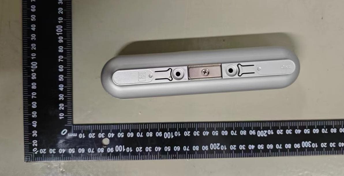
Click to zoom
Application Details
- Equipment Class
- DTS - Digital Transmission System
- Date of Grant
- Jun 12, 2024
- Application Purpose
- Original Equipment
- Date of Application
- Jun 12, 2024
- Equipment Note
- Heatic 2+
- Frequency Range
- 2405.00000000 - 2475.00000000
- Company
- Butlr Technologies Inc.
- Country
- United States
Documents & Files
Document Text
Text extracted from the exhibit documents filed with the FCC. Open a document above to read the original.
Users Manual
Thank you for choosing Bu tlr—the AI Data Platform for Anonymous People Sensing. We are excited for you to explore the fu ture of spatial design with our innovative solu tions. Whether you aim to gain insights on indoor traffic, monitor human activities, optimize desk u tilization, or enhance operational efficiency, we hope your experience with Bu tlr is both seamless and rewarding. For additional support, please visit our Learning Center at support.bu tlr.io or contact your Bu tlr representative. We are eager to partner with you as we transform sensors into the nerve cells of tomorrow’s built environments. This Quick Start Guide provides an overview for setting up Heatic sensors and gateways. For a detailed step-by-step guide, please visit support.bu tlr.io. Quick Start Guide Heatic 2+ 06 _ Update device info on Studio 08 _ Post-installation QA Device pairing and configuration 07 _ Access Spatial Insights via Butlr Dashboard or by Integrating the Butlr API 09 _ Update the virtual placeholder to accurately reflect device-specific information, such as the MAC address, serial number, installation height, orientation, mounting method, and precise location. Modify the device's custom fields as necessary. Use Studio and the materials provided by Bu tlr to verify the correct installation of devices and ensure data quality, optimizing sensor performance. If onsite support is unavailable, Bu tlr offers remote pairing and configuration options. Please contact your Bu tlr representative for more information. Bu tlr enjoys collaborating with your development team. Our Product and Engineering teams will assist your engineers throughou t the integration process to ensure your success from the start. www.bu tlr.com Burlingame, California, USA © 2024 Bu tlr Technologies Inc. All rights reserved. Mac address - - - - - - - - Changes or modifications not expressly approved by the party responsible for compliance could void the user's au thority to operate the equipment This equipment has been tested and found to comply with the limits for a Class A digital device, pursuant to Part 15 of the FCC Rules. These limits are designed to provide reasonable protection against harmful interference when the equipment is operated in a commercial environment. This equipment generates, uses, and can radiate radio frequency energy and, if not installed and used in accordance with the instruction manual, may cause harmful interference to radio communications. Operation of this equipment in a residential area is likely to cause harmful interference in which case the user will be required to correct the interference at his own expense. “This device complies with part 15 of the FCC Rules. Operation is subject to the following two conditions: (1) This device may not cause harmful interference, and (2) this device must accept any interference received, including interference that may cause undesired operation.” “In order to comply with FCC/ISED RF Exposure requirements, this device must be installed to provide at least 20 cm separation from the human body at all times. Lors de l'installation et du fonctionnement de cet équipement, la distance minimale entre le radiateur et le corps doit être de 20 cm “This device contains licence-exempt transmitter(s)/receiver(s) that comply with Innovation, Science and Economic Development Canada’s licence-exempt RSS(s). Operation is subject to the following two conditions: 1. This device may not cause interference. 2. This device must accept any interference, including interference that may cause undesired operation of the device.” “L’émetteur/récepteur exempt de licence contenu dans le présent appareil est conforme aux CNR d’Innovation, Sciences et Développement économique Canada applicables aux appareils radio exempts de licence. L’exploitation est au torisée aux deux conditions suivantes: 1. L’appareil ne doit pas produire de brouillage ; 2. L’appareil doit accepter tou t brouillage radioélectrique subi, même si le brouillage est susceptible d’en compromettre le fonctionnement.” This is only required if product is within ICES-003 scope and is not exempt: * Insert either “A” or “B”, bu t not both, to identify the applicable Class of the device used for compliance verification. “CAN ICES-3 (*)/NMB-3(*)” Cela n'est nécessaire que si le produit entre dans le champ d'application de la norme ICES-003 et n'est pas exempté : * Insérer "A" ou "B", mais pas les deux, pour identifier la classe applicable de l'appareil u tilisé pour la vérification de la conformité. "CAN ICES-3 (*)/NMB-3(*)" If you have multiple spaces or complex floorplans, Bu tlr can help with sensor placement planning. Please contact your Bu tlr representative for more information. WiFi, Ethernet or LTE Traffic Mode Presence Mode 01 _ Log in to Butlr dashboard 03 _ 04 _ Turn on Heatic Sensor(s) 02 _ Set up your virtual space in Studio 05 _ Mount Heatic Sensor(s) Plug in Hive and connect to the Internet https://app.bu tlr.io When switched on, unpaired Heatic Sensors set to the default Network ID will flash a yellow LED. If this does not occur, first ensure that the batteries are correctly installed. Next, verify that the PIR module is intact before mounting the sensor. For further assistance, contact your Bu tlr representative or submit a support ticket. Traffic Mode provides aggregated totals of 'in' and 'ou t' movements based on a sensor's orientation, a user-defined door line, and the direction of entry. It is recommended to mount the sensor above entrances using either a Wall Mount or Ceiling Mount for optimal performance. Learning Center -> Mounting Guide Presence Mode supplies the number and coordinates of individuals within its coverage area. For best results, it is recommended to mount the sensor in open areas and meeting rooms using a Ceiling Mount. Different Hive versions may include varying numbers and types of antennas. The illustration above is for demonstration purposes only. Antennas Device Hive Plug inConnect Ether…
Text truncated - open the document above for the full version.
Cover Letter(s)
Butlr Technologies Inc. 5/20/2024 Nemko North America, Inc. 303 River Road Ottawa, Ontario, Canada K1V 1H2 REQUEST FOR CONFIDENTIALITY - FCC FCC ID: 2AZPC-BHS2P Pursuant to Sections 0.457(d)(1)(ii) and 0.45 9 of the Commission’s Rules and FCC Guidance document 726920, we hereby request confidential treatment of information accompanying this application as outlined below: PERMANENT LONG-TERM CONFIDENTIALITY: Schematics Bill of Materials/Parts List Block Diagrams Theory of Operation The above information contains trade secrets and proprietary information not customarily released to the public. The public disclosure of this information might be harmful to t he applicant and provide unjustified benefits t o its competitors. The Applicant understands that pursuant to Rule 0.457(d)(1)(ii), disclosure of this Application and all accompanying materials will not be made before the date of the Grant for this Application. Sincerely, Signed: Printed name: Jiani Zeng Title: Chief Product Officer
External Photos
Description:FrontView Description:BackView Description:SideView Description:SideView Description:SideView Description:SideView
ID Label/Location Info
Mac标签 SN 标签 认证标签
Internal Photos
Description:InternalPhoto Description:InternalPhoto Description:InternalPhoto Description:InternalPhoto Description:InternalPhoto Description:InternalPhoto
RF Exposure Info
TESTREPORT FCCID2AZPC-BHS2P Applicant:ButlrTechnologiesInc. ProductName:Heatic2+ ModelNo.:HS08WL90PR CVCTestingTechnologyCo.,Ltd. TestReportNo.: FCC2024-0018-H TestReportNo.FCC2024-0018-HPage 2 of13 LTC-R-7093-RF-Part15E-A0 ProductNameHeatic2+TradeMark Type/ModelHS08WL90PRSampleStatus— ApplicantButlrTechnologiesInc. ApplicantAddressSuite510,800AirportBlvd.BurlingameCA94010,USA ManufacturerButlrTechnologiesInc. Manufacturer Address Suite510,800AirportBlvd.BurlingameCA94010,USA ProducerShenzhenSaidaxinTechnologyCo.,Ltd. ProducerAddress 6/F,Buildingl,SaituDigitalTechnologyPark,BulanRoad,JihuaStreet, LonggangShenzhen,Guangdong Quantityofsample1pcs Sample Identification 1-1 TestedAccording To FCCPart2(Section2.1093) KDB447498D04v01 IEEEC95.1 TestItemRFExposure ReceivingDate2024.5.7DateofTesting2024.5.14 Testconclusion Theequipmentundertestwasfoundto comply withtherequirementsof thestandardsapplied. FinalVerdict:Pass. SealofCVC Dateofissue:2024-6-5 Note1:ThistestreportrelatesonlytotheEUT,andshallnotbereproducedexceptinfull,withoutwrittenapprovalofCVC. Approvedby: ChenHuawen Reviewedby: XuZhenfei Testedby: LuWeiji TestReportNo.FCC2024-0018-HPage 3 of13 LTC-R-7093-RF-Part15E-A0 TABLEOFCONTENTS 1.GENERALPRODUCTINFORMATION...............................................................................................................4 1.1GENERALINFORMATION....................................................................................................................................4 2.HUMANEXPOSUREASSESSMENT...................................................................................................................5 2.1RFEXPOSURETESTEXEMPTIONSFORSINGLESOURCE...........................................................................................5 2.2RFEXPOSURETESTEXEMPTIONSFORSIMULTANEOUSTRANSMISSIONSOURCES........................................................9 2.3CLASSIFICATION........................................................................................................................................10 3.RFOUTPUTPOWER......................................................................................................................................11 4.TESTRESULTS................................................................................................................................................12 TestReportNo.FCC2024-0018-HPage 4 of13 LTC-R-7093-RF-Part15E-A0 1.GeneralProductInformation 1.1Generalinformation ProductNameHeatic2+ ModelNo.HS08WL90PR AdditionalmodelN/A PowerSupplyDC3.6V SerialNumber(SN)B2LBB2409000035 AntennaTypeInternalAntenna AntennaGain2.00dBi(providedbyclient) BeamforminggainUnsupported(providedbyclient) FrequencyRange2405~2475MHz OperateTemp.Range0~40°C Note : 1.TheinformationoftheEUTisdeclaredbythemanufacturer. 2.Thelaboratoryisnotresponsiblefortheproducttechnicalspecificationprovidedbytheclient. TestReportNo.FCC2024-0018-HPage 5 of13 LTC-R-7093-RF-Part15E-A0 2.HumanExposureAssessment 2.1RFExposureTestExemptionsforSingleSource 2.1.11-mWTestExemption The1mWTestExemptionof§1.1307(b)(3)(i)(A)appliesforsinglefixed,mobile,and portableRFsourceswithavailablemaximumtime-averagedpowerofnomorethan1mW, regardlessofseparationdistance. The1mWblanketexemptionappliesatseparationdistanceslessthan0.5cm,includingwhere thereisnoseparation.Thisexemptionshallnotbeusedinconjunctionwithotherexemption criteriaotherthanthoseformultipleRFsourcesinparagraph§1.1307(b)(3)(ii)(A). The1mWexemptionisindependentofservicetypeandcoversthefullrangeof100kHzto 100GHz,butitshallnotbeusedinconjunctionwithotherexemptioncriteriaorindeviceswith higher-powertransmittersoperatinginthesametime-averagingperiod.Exposurefromsuch higher-powertransmitterswouldinvalidatetheunderlyingassumptionthatexposurefromthe lower-powertransmitteristheonlycontributortoSARintherelevantvolumeoftissue. 2.1.2SAR-BasedExemption Amorecomprehensiveexemption,consideringavariablepowerthresholdthatdependsonboth theseparationdistanceandpower,isprovidedin§1.1307(b)(3)(i)(B).Thisexemptionis applicabletothefrequencyrangebetween300MHzand6GHz,withtestseparationdistances between0.5cmand40cm,andforallRFsourcesinfixed,mobile,andportabledeviceexposure conditions. Accordingly,aRFsourceisconsideredanRFexemptdeviceifitsavailablemaximumtime averaged(matchedconducted)poweroritseffectiveradiatedpower(ERP),whicheverisgreater, arebelowaspecifiedthreshold.Thisexemptionthresholdwasderivedbasedongeneral population1-gSARrequirements. Generalfrequencyandseparation-distancedependentMPE-basedeffectiveradiatedpower (ERP)thresholdsareinTableB.1[Table1of§1.1307(b)(1)(i)(C)]tosupportanexemption fromfurtherevaluationfrom300kHzthrough100GHz. ThetableappliestoanyRFsource(i.e.,singlefixed,mobile,andportabletransmitters)and specifiespoweranddistancecriteriaforeachofthefivefrequencyrangesusedfortheMPE limits.Thesecriteriaapplyatseparationdistancesfromanypartoftheradiatingstructureofat leastλ/2π.ThethresholdsarebasedonthegeneralpopulationMPElimitswithasingleperfect reflection,outsideofthereactivenear-field,andinthemainbeamoftheradiator. FormobiledevicesthatarenotexemptperTableB.1[Table1of§1.1307(b)(1)(i)(C)]at distancesfrom20cmto40cmandin0.3GHzto6GHz,evaluationofcompliancewiththe exposurelimitsin§1.1310isnecessaryiftheERPofthedeviceisgreaterthanERP20cmin Formula(B.1)[repeatedfrom§2.1091(c)(1)and§1.1307(b)(1)(i)(B)] TestReportNo.FCC2024-0018-HPage 6 of13 LTC-R-7093-RF-Part15E-A0 TABLEB.1—THRESHOLDSFORSINGLERFSOURCES SUBJECTTOROUTINEENVIRONMENTALEVALUATION RFSourceFrequencyMinimumDistance Threshold ERP f L MHzf H MHzλ L /2πλ H /2πW 0.3-1.34159m-35.6m1920R 2 1.34-3035.6m-1.6m3450R 2 /f 2 30-3001.6m-159mm3.83R 2 300-1500159mm-31.8mm0.0128R 2 /f 2 1500-10000031.8mm-0.5mm19.2R 2 SubscriptsLandHarelowandhigh;λiswavelength. From§1.1307(b)(3)(i)(C),modifiedbyaddingMinimumDistancecolumns. 2.1.3MPE-BasedExemption AnalternativetotheSAR-basedexemptionisprovidedin§1.1307(b)(3)(i)(C),foramuchwider frequencyrange,from300kHzto100GHz,applicableforseparationdistancesgrea…
Text truncated - open the document above for the full version.
Test Report
TESTREPORT FCCID2AZPC-BHS2P Applicant:ButlrTechnologiesInc. ProductName:Heatic2+ ModelNo.:HS08WL90PR CVCTestingTechnologyCo.,Ltd. TestReportNo.: FCC2024-0018-RF TestReportNo.FCC2024-0018-RFPage 2 of 38 LTC-R-7092-RF-Part15C-A1 Applicant Name:ButlrTechnologiesInc. Address:Suite510,800AirportBlvd.BurlingameCA94010,USA Manufacturer Name:ButlrTechnologiesInc. Address:Suite510,800AirportBlvd.BurlingameCA94010,USA EquipmentUnderTest ProductName:Heatic2+ ModelNo.:HS08WL90PR Trademark: Serialno.:B2LBB2409000035 Sampling:1-1 DateofReceipt.2024.5.7DateofTesting2024.5.14 TestSpecificationTestResult FCCCFR47Part15CRadioFrequencyDevices ANSIC63.10-2020/Cor1-2023 KDB558074D0115.247MeasGuidancev05r02 PASS EvaluationofTestResult Theequipmentundertestwasfoundtocomplywiththe requirementsofthestandardsapplied. SealofCVC IssueDate:2024-6-5 Approvedby: ChenHuawen Reviewedby: XuZhenfei Testedby: LuWeiji OtherAspects:NONE. Abbreviations:Pass=passedFail=failedN/A=notapplicableEUT=equipment,sample(s)undertested Note:ThistestreportrelatesonlytotheEUT,andshallnotbereproducedexceptinfull,withoutwrittenapprovalofCVC. TestReportNo.FCC2024-0018-RFPage 3 of 38 LTC-R-7092-RF-Part15C-A1 TABLEOFCONTENTS 1.GENERALPRODUCTINFORMATION.................................................................................................................4 1.1GENERALINFORMATION .............................................................................................................................................4 2.TESTSITES..............................................................................................................................................................5 2.1TESTFACILITIES .........................................................................................................................................................5 2.2DESCRIPTIONOFNON-STANDARDMETHODANDDEVIATIONS ................................................................................5 2.3LISTOFTESTANDMEASUREMENTINSTRUMENTS...................................................................................................5 3.TESTCONFIGURATION .........................................................................................................................................6 3.1TESTMODE ................................................................................................................................................................6 3.2DUTYCYCLE ...............................................................................................................................................................8 4.SUMMARYOFMEASUREMENTRESULTS........................................................................................................9 5.MEASUREMENTPROCEDURE.........................................................................................................................10 5.1CONDUCTEDEMISSION ............................................................................................................................................10 5.2RADIATEDEMISSION................................................................................................................................................13 5.3MAXIMUMCONDUCTEDOUTPUTPOWER.................................................................................................................25 5.4MINIMUM6DBBANDWIDTH .....................................................................................................................................27 5.5OCCUPIEDCHANNELBANDWIDTH ...........................................................................................................................29 5.6BANDEDGEMEASUREMENT....................................................................................................................................31 5.7MAXIMUMPOWERSPECTRALDENSITY..................................................................................................................33 5.8SPURIOUSRFCONDUCTEDEMISSIONS .................................................................................................................35 6.APPENDIXX...........................................................................................................................................................37 TestReportNo.FCC2024-0018-RFPage 4 of 38 LTC-R-7092-RF-Part15C-A1 1.GeneralProductInformation 1.1Generalinformation ProductNameHeatic2+ ModelNo.HS08WL90PR AdditionalmodelN/A PowerSupplyDC3.6V SerialNumber(SN)B2LBB2409000035 HW-ReleaseNOHeaticSensorWireless_V1_DVT1 SW-ReleaseNOHeaticSmartmeshV3.0.1 specificpowersettingsDefault AntennaTypeInternalAntenna AntennaGain2.00dBi(providedbyclient) BeamforminggainUnsupported(providedbyclient) FrequencyRange2405~2475MHz ChannelNumber15Channels TypeofModulationQPSK Max.ConductedPower7.01dBm OperateTemp.Range0~40°C Note: 1.TheinformationoftheEUTisdeclaredbythemanufacturer. 2.Thelaboratoryisnotresponsiblefortheproducttechnicalspecificationprovidedbytheclient. TestReportNo.FCC2024-0018-RFPage 5 of 38 LTC-R-7092-RF-Part15C-A1 2.TestSites 2.1TestFacilities ThetestsandmeasurementsrefertothisreportwereperformedbyRFtestingLab.ofCVCTesting TechnologyCo.,Ltd. Add.:No.3,TiantaiyiRoad,KaitaiAvenue,ScienceCity,Guangzhou,Guangdong,510663,People's RepublicofChina Telephone:+86-20-32293888 Fax:+86-20-32293889 FCC(Testfirmdesignationnumber:CN1282) IC(TestfirmCABidentifiernumber:CN0103) 2.2DescriptionofNon-standardMethodandDeviations Thetestingandmeasurementmethodsusedinthisreportareappliedbyallstandardmethods.Notany non-standardmethodordeviationfromtheusedstandardswasused. 2.3ListofTestandMeasurementInstruments RefertoAppendixX. TestReportNo.FCC2024-0018-RFPage 6 of 38 LTC-R-7092-RF-Part15C-A1 3.TestConfiguration 3.1TestMode TheEUThasbeenassociatedwithperipheralsandconfigurationoperatedinamannertendedto maximizeitsemissioncharacteristicsinatypicalapplication. TestModeAntennaDeliveryTestChannel 802.15.4MeshNetworkingRadio 1TX/1RX0,7,14 Theradiat…
Text truncated - open the document above for the full version.
Test Report
AppendixA:DTSBandwidth TestResult TestModeAntennaChannel DTSBW [MHz] FL[MHz]FH[MHz]Limit[MHz]Verdict ZIGBAnt1 24051.552404.292405.840.5PASS 24401.572439.292440.860.5PASS 24751.602474.252475.850.5PASS TestGraphs ZIGB_Ant1_2405 ZIGB_Ant1_2440 ZIGB_Ant1_2475 AppendixB:OccupiedChannelBandwidth TestResult TestModeAntennaChannel OCB[MHz] FL[MHz]FH[MHz]Limit[MHz]Verdict ZIGBAnt1 24052.3782403.86112406.2388------ 24402.4082438.86112441.2687------ 24752.4382473.84122476.2787------ TestGraphs ZIGB_Ant1_2405 ZIGB_Ant1_2440 ZIGB_Ant1_2475 AppendixC:Maximumconductedoutputpower TestResult TestModeAntennaChannelResult[dBm]Limit[dBm] E.I.R.P [dBm] E.I.R.P Limit(dBm) Verdict ZIGB Ant124057.01≤309.01≤36.00PASS Ant124406.48≤308.48≤36.00PASS Ant124756.77≤308.77≤36.00PASS AppendixD:Maximumpowerspectraldensity TestResult TestModeAntennaChannelResult[dBm/3-100kHz]Limit[dBm/3kHz]Verdict ZIGBAnt1 2405-8.21≤8.00PASS 2440-8.15≤8.00PASS 2475-5.23≤8.00PASS TestGraphs ZIGB_Ant1_2405 ZIGB_Ant1_2440 ZIGB_Ant1_2475 AppendixE:Bandedgemeasurements TestResult TestModeAntennaChNameChannelRefLevel[dBm]Result[dBm]Limit[dBm]Verdict ZIGBAnt1 Low2405-4.09-40.01≤-24.09PASS High24750.46-49.84≤-19.54PASS TestGraphs ZIGB_Ant1_Low_2405 ZIGB_Ant1_High_2475 AppendixF:ConductedSpuriousEmission TestResult TestModeAntennaChannel FreqRange [MHz] RefLevel [dBm] Result[dBm]Limit[dBm]Verdict ZIGBAnt1 2405 Reference2.352.35---PASS 30~10002.35-52.89≤-17.65PASS 1000~265002.35-48.22≤-17.65PASS 2440 Reference1.891.89---PASS 30~10001.89-53.27≤-18.11PASS 1000~265001.89-48.21≤-18.11PASS 2475 Reference1.271.27---PASS 30~10001.27-52.8≤-18.73PASS 1000~265001.27-48.63≤-18.73PASS TestGraphs ZIGB_Ant1_2405_0~Reference ZIGB_Ant1_2405_30~1000 ZIGB_Ant1_2405_1000~26500 ZIGB_Ant1_2440_0~Reference ZIGB_Ant1_2440_30~1000 ZIGB_Ant1_2440_1000~26500 ZIGB_Ant1_2475_0~Reference ZIGB_Ant1_2475_30~1000 ZIGB_Ant1_2475_1000~26500 AppendixG:DutyCycle TestResult TestModeAntennaChannel Transmission Duration[ms] Transmission Period[ms] Duty Cycle[%] LimitVerdict ZIGBAnt1 24051.086.2817.20------ 24401.086.2517.28------ 24751.086.2517.28------ TestGraphs ZIGB_Ant1_2405 ZIGB_Ant1_2440 ZIGB_Ant1_2475
Test Setup Photos
Description:RadiatedEmission ( 9k~30MHz ) Description:RadiatedEmission(30M~1GHz) Description:RadiatedEmission ( 1G~18GHz ) Description:RadiatedEmission ( 18G~40GHz ) Description: Conducted:Maximumconductedoutputpower/Minimum6dBbandwidth/Occupied ChannelBandwidth/BandEdgeMeasurement/MaximumPowerspectraldensity/ SpuriousRFConductedEmissions
Contact Information
Applicant
Jiani Zeng
Test Firm
CVC Testing Technology Co., Ltd.Lai Wenjing
[email protected]862032293684
Technical Specifications
| # | Rule Parts | Frequency Range | Power Output |
|---|---|---|---|
| 1 | 15C | 2.40 GHz - 2.48 GHz | 5.02 mW |
Other Applications from Butlr Technologies Inc.
2AZPC-GWDSRKWF
Sep 30, 2024Hive
Equipment Class
NII - Unlicensed National Information Infrastructure TX