2AZQ7SLU-A1000-BUWB Indoor Anchor
Wanma yun Electronic Technology (zhengzhou) Co., Ltd.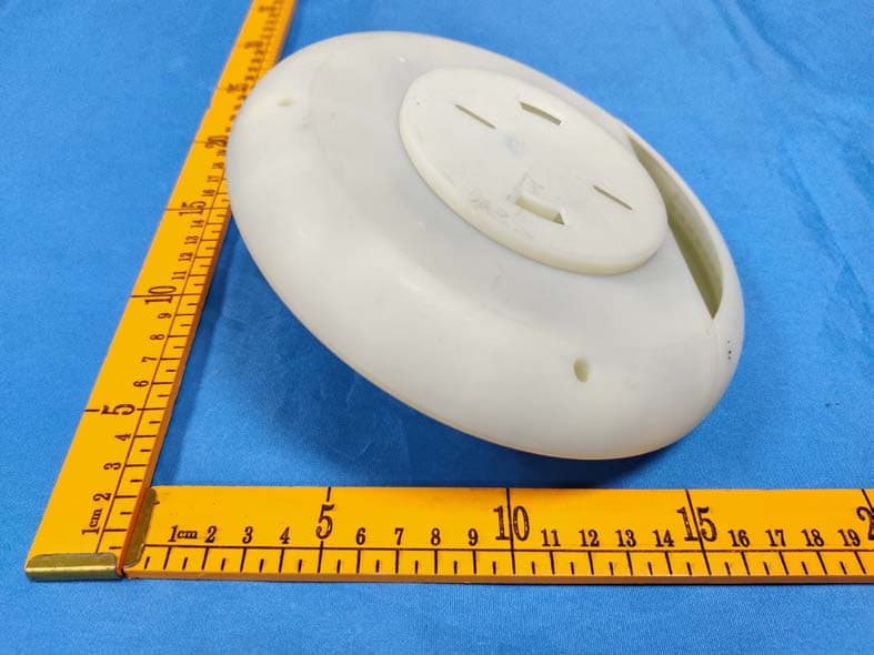
Click to zoom
Application Details
- Equipment Class
- DTS - Digital Transmission System
- Date of Grant
- Jul 12, 2021
- Application Purpose
- Original Equipment
- Date of Application
- Jun 24, 2021
- Equipment Note
- UWB Indoor Anchor
- Frequency Range
- 2412.00000000 - 2462.00000000
- Country
- China
Documents & Files
Document Text
Text extracted from the exhibit documents filed with the FCC. Open a document above to read the original.
Users Manual
SLU- A1000-B SLU-A1000-B SLU- A1000-B 1 Content 1.Product Specifications................................................................ .......................... 2 2.Product Picture................................................................................................ ..... 3 3. System Introduction................................................................ ............................ 4 3.1 System composition................................................................ ........................ 4 3.2 Introduction of location mode................................................................ ........ 5 4. Anchor selection and installation................................................................ ........ 7 4.1 Anchor selection................................................................ ............................. 7 4.2 Anchor Installation ...................................................................................... 10 5. Network Setting Up ........................................................................................... 12 6.Warning ............................................................................................................... 13 SLU- A1000-B 2 1.Product Specifications Specification Dimension φ 175mm Net working RJ45 / Wifi Interface POE, Type C, SMA, Reset IP Grade IP50 Working Environment Working Temperature: -30~70 °C Humidity:10%~90% UWB Specification Frequency Band CH2: 3993.6MHz; CH5: 6489.6MHz Speed 6.8Mbps Output Power ≤ -41.3dBm/MHz Channel Support channel 2&channel 5 Protocol Standard IEEE 802.15.4-2011 UWB WIFI Specification Frequency 2412MHz-2462MHz Modulation CCK, OFDM SLU- A1000-B 3 Wireless Data Rate (Mbps) 802.11b: 1, 2,5.5,11 802.11g: 6,9,12,18,24,36,48,54 802.11n: MCS0~7,HT20 reach up to72.2Mbps, HT40 reach up to150Mbps HT40 reach up to300Mbps (2T2R) Rx Sensitivity -98dBm (Min) TX Power 21.36dBm (Max) IEEE Standards IEEE 802.11b/g/n 2.Product Picture Product Picture: LED status: LED #1: Power on: Green, Power off: light off LED#2: WIFI on: Green,WIFI data transmission: Green Flash, WIFI off: light off LED#3: RJ45 POEon: Green, RJ45 data transmission: Green Flash, RJ45 POE off: light off LED #3 LED #2 SLU- A1000-B 4 3. System Introduction 3.1 System composition The indoor location system is composed of web application platform, location engine, anchors and tags. 1. Tag The tag is the terminal of UWB location system, which is mainly responsible for periodically sending location message to the anchor and receiving setting messages from the anchor. 2. Anchor The UWB anchor is an important part of the whole location system. Its main function is to receive and parse the information reported by the tag, and then transmit it to the location engine. The anchor deployment has a direct impact on the location accuracy of the entire system, so special attention should be paid to the selection of anchor location. The following sections will specify the deployment principles of anchor location selection. 3. Location engine The function of location engine is to receive the location message after the anchor is parsed, and calculate the anchor location through a certain SLU- A1000-B 5 algorithm, or send some parameter configuration information to the anchor. 4. Web application platform We b application platform is an upper application based on the development of location data. Users can directly use the functions provided by the Web application, or customize the development based on the secondary development interface provided by the Web platform. 3.2 Introduction of location mode Location System Architecture Core Location Engine Blink AnchorAnchor Anchor Anchor TagTagTag Tag Blink TagPositioning Positioning Network protocol 2 nd level Positioning System Marginal Layer Positioning network server Location data release Message Services Push positioning /Data Subscription APP SDK webApplication 3 rd party Video monitoring system Network Control Data delivering Push positioning Data subscription Registry Center Security Gateway (Router server SSL policy ) Account management(Authentication, Role control...) Camera Service IdI-web Service IdI-manage service IdI-map Service Date Persistence Layer Save/Updated Business Data NOSQL Database MYSQL Data Cache Data Storage Support Secondary Development kit and Interface Micro-service framework Security gate way (Router server SSLpolicy) Security control from three aspects (Application, Function, Interface) Indoor positioning system has three mode: Zero-dimensional positioning mode (existential positioning) One-dimensional positioning mode Two-dimensional positioning mode 1. Zero-dimensional positioning mode Zero-dimensional positioning mode, also known as existential positioning, refers to that when a tag enters a specific positioning area, the positioning system only identifies the presence of the tag in the area, but does not judge the specific location of the tag. It is a kind of coarse precision positioning, which is generally suitable for small-enclosed area. SLU- A1000-B 6 2. One-dimensional positioning mode One-dimensional positioning mode is used to locate only one dimension in three-dimensional world, also known as “linear positioning”. When the tag enters the one-dimensional positioning area, the system can accurately locate the tag on a straight line, which is generally applied in narrow and long areas such as tunnels and corridors. 3. Two-dimensional positioning mode Two-dimensional positioning mode refers to the positioning of two dimensions in three-dimensional world, also known as “planar positioning”. When the tag enters the two-dimensional positioning area, the system can accurately locate the planar position of the tag. It is often used in office, warehouse, factories and other large areas, and is the most commonly used positioning mode of indoor positioning system. SLU- A1000-B 7 4. Anchor selection and installation 4.1 Anchor selection To a large extend, the s…
Text truncated - open the document above for the full version.
External Photos
EXHIBIT B - EUT EXTERNAL PHOTOGRAPHS This port is reserved and blocked by the manufacturer, can’t be used by the User.
Internal Photos
EXHIBIT C - EUT INTERNAL PHOTOGRAPHS UWB antenna 2.4G Wi-Fi Antenna1 2.4G Wi-Fi Antenna 0
RF Exposure Info
ShenzhenGlobalTestServiceCo.,Ltd. No.7-101and8A-104,Building7and8,DCCCulturalandCreativeGarden,No.98,PingxinNorthRoad, ShangmuguCommunity,PinghuStreet,LonggangDistrict,Shenzhen,Guangdong RFExposureevaluation ReportReferenceNo........................: FCCID..................................................: GTS20210419013-1-2 2AZQ7SLU-A1000-B Compiledby (position+printedname+signature) .. :FileadministratorsYiliaZhong Supervisedby (position+printedname+signature)..:TestEngineerJennyZeng Approvedby (position+printedname+signature)..: ManagerSimonHu Dateofissue ......................................... :May.24,2021 RepresentativeLaboratoryName . :ShenzhenGlobalTestServiceCo.,Ltd. Address.................................................: No.7-101and8A-104,Building7and8,DCCCulturalandCreative Garden,No.98,PingxinNorthRoad,ShangmuguCommunity, PinghuStreet,LonggangDistrict,Shenzhen,Guangdong Applicant’sname...............................:WanmayunElectronicTechnology(zhengzhou)Co.,Ltd. Address.................................................: IntelligentTerminalMobilePhoneIndustrialPark,CrossingatXinga ngAvenueandRenminRoad,ZhengzhouAirportDistrict,China,45 1162 Testspecification..............................: Standard................................................: 47CFR§1.1310 47CFR§2.1091 KDB447498v06 TRFOriginator ...................................... :ShenzhenGlobalTestServiceCo.,Ltd. MasterTRF ........................................... :Dated2014-12 ShenzhenGlobalTestServiceCo.,Ltd.Allrightsreserved. Thispublicationmaybereproducedinwholeorinpartfornon-commercialpurposesaslongasthe ShenzhenGlobalTestServiceCo.,Ltd.isacknowledgedascopyrightownerandsourceofthematerial. ShenzhenGlobalTestServiceCo.,Ltd.takesnoresponsibilityforandwillnotassumeliabilityfordamages resultingfromthereader'sinterpretationofthereproducedmaterialduetoitsplacementandcontext. Testitemdescription ........................ :UWBIndoorAnchor TradeMark ............................................ :N/A Manufacturer ......................................... :WanmayunElectronicTechnology(zhengzhou)Co.,Ltd. Model/Typereference.........................:SLU-A1000-B ListedModels......................................:N/A HardwareVersion...............................:V0.350 SoftwareVersion .................................. :EVT Rating.....................................................: DC5.0Vbyadapter DC53.5VbyPOE Result ..................................................... :PASS ReportNo.:GTS20210419013-1-2Page 2 of 12 TESTREPORT TestReportNo.: GTS20210419013-1-2 May.24,2021 ______________________________________________________________________________________________ Dateofissue EquipmentunderTest:UWBIndoorAnchor Model/Type:SLU-A1000-B Listedmodel:N/A Applicant :WanmayunElectronicTechnology(zhengzhou)Co.,Ltd. Address : IntelligentTerminalMobilePhoneIndustrialPark,CrossingatXingang AvenueandRenminRoad,ZhengzhouAirportDistrict,China,451162 Manufacturer :WanmayunElectronicTechnology(zhengzhou)Co.,Ltd. Address : IntelligentTerminalMobilePhoneIndustrialPark,CrossingatXingang AvenueandRenminRoad,ZhengzhouAirportDistrict,China,451162 TestResult : PASS Thetestreportmerelycorrespondstothetestsample. Itisnotpermittedtocopyextractsofthesetestresultwithoutthewrittenpermissionofthetest laboratory. ReportNo.:GTS20210419013-1-2Page 3 of 12 Contents 1.SUMMARY .......................................................................................................................................................................... 4 1.1EUTCONFIGURATION ......................................................................................................................................................... 4 1.2PRODUCTDESCRIPTION ...................................................................................................................................................... 4 2.TESTENVIRONMENT .......................................................................................................................................................... 5 2.1ADDRESSOFTHETESTLABORATORY ...................................................................................................................................... 5 2.2TESTFACILITY .................................................................................................................................................................... 5 2.3ENVIRONMENTALCONDITIONS ............................................................................................................................................. 5 2.4STATEMENTOFTHEMEASUREMENTUNCERTAINTY .................................................................................................................. 5 3.METHODOFMEASUREMENT ............................................................................................................................................ 6 3.1APPLICABLESTANDARD ....................................................................................................................................................... 6 3.2REQUIREMENT ................................................................................................................................................................... 6 3.3LIMIT ............................................................................................................................................................................... 6 3.4MPECALCULATIONMETHOD .............................................................................................................................................. 7 3.5ANTENNAINFORMATION ..................................................................................................................................................... 7 4.CONDUCTEDPOWERRESULTS ........................................................................................................................................... 8 5.MANUFACTURINGTOLERANCE .............…
Text truncated - open the document above for the full version.
Test Report
ShenzhenGlobalTestServiceCo.,Ltd. No.7-101and 8A-104,Building7 and 8, DCCCulturaland CreativeGarden,No.98,PingxinNorthRoad, ShangmuguCommunity,PinghuStreet,LonggangDistrict,Shenzhen,Guangdong FCC PART15 SUBPARTC TESTREPORT FCC PART15.247 ReportReferenceNo ........................: FCCID.................................................: GTS20210419013-1-1 2AZQ7SLU-A1000-B Compiled by ( position+printedname+signature)..:File administratorsYilia Zhong Supervisedby ( position+printedname+signature) .. :Test EngineerJennyZeng Approvedby ( position+printedname+signature) .. : ManagerSimonHu Dateof issue.........................................:May.24,2021 RepresentativeLaboratoryName . :ShenzhenGlobalTestServiceCo.,Ltd. Address.................................................: No.7-101and 8A-104,Building7 and 8, DCCCulturaland Creative Garden,No.98,PingxinNorthRoad,ShangmuguCommunity,Pinghu Street,LonggangDistrict,Shenzhen,Guangdong,China Applicant’s name...............................:Wanmayun ElectronicTechnology(zhengzhou)Co., Ltd. Address ................................................. : IntelligentTerminalMobilePhoneIndustrialPark,Crossingat Xingang Avenueand RenminRoad,ZhengzhouAirportDistrict,China,451162 Testspecification .............................. : Standard ................................................ : FCCPart 15.247:Operationwithinthe bands902-928MHz,2400- 2483.5MHzand 5725-5850MHz TRF Originator ...................................... :ShenzhenGlobalTest ServiceCo.,Ltd. MasterTRF ........................................... :Dated2014-12 ShenzhenGlobalTestServiceCo.,Ltd.All rightsreserved. This publicationmay be reproducedin wholeor in part for non-commercialpurposesas long as the Shenzhen GlobalTest ServiceCo.,Ltd.is acknowledgedas copyrightownerand sourceof the material.ShenzhenGlobal Test ServiceCo.,Ltd.takesno responsibilityfor and will not assumeliabilityfor damagesresultingfrom the reader'sinterpretationof the reproducedmaterialdue to its placementand context. Testitemdescription........................:UWBIndoorAnchor TradeMark............................................: N/A Manufacturer.........................................:Wanmayun ElectronicTechnology(zhengzhou)Co., Ltd. Model/Typereference.........................: SLU-A1000-B ListedModels......................................: N/A OperationFrequency..........................:From2412MHzto 2462MHz HardwareVersion...............................:V0.350 SoftwareVersion..................................:EVT Rating.....................................................: DC 5.0 V by adapter DC 53.5Vby POE Result.....................................................:PASS ReportNo.: GTS20210419013-1-1Page 2 of 67 T E S T R E P O R T TestReportNo. : GTS20210419013-1-1 May.24,2021 ____________________________________________________________________________________ Dateof issue EquipmentunderTest:UWBIndoorAnchor Model/Type:SLU-A1000-B Listedmodel:N/A Applicant :Wanmayun ElectronicTechnology(zhengzhou)Co., Ltd. Address : IntelligentTerminalMobilePhoneIndustrialPark,Crossingat Xingang Avenueand RenminRoad,ZhengzhouAirportDistrict,China,451162 Manufacturer :Wanmayun ElectronicTechnology(zhengzhou)Co., Ltd. Address : IntelligentTerminalMobilePhoneIndustrialPark,Crossingat Xingang Avenueand RenminRoad,ZhengzhouAirportDistrict,China,451162 Test Result:PASS The test reportmerelycorrespondsto the test sample. It is not permittedto copyextractsof thesetest resultwithoutthe writtenpermissionof the test laboratory. ReportNo.: GTS20210419013-1-1Page 3 of 67 Contents 1. TESTSTANDARDS.......................................................................................................................................................4 2. SUMMARY ....................................................................................................................................................................... 5 2.1. GeneralRemarks ................................................................................................................................................. 5 2.2. ProductDescription ............................................................................................................................................. 5 2.3. EquipmentUnderTest........................................................................................................................................6 2.4. Shortdescriptionof the EquipmentunderTest (E UT)...................................................................................6 2.5. EUT operationmode............................................................................................................................................6 2.6. BlockDiagramof Test Setup .............................................................................................................................. 6 2.7. RelatedSubmittal(s)/ Grant(s) ......................................................................................................................... 7 2.8. EUT ExerciseSoftware ....................................................................................................................................... 7 2.9. SpecialAccessories.............................................................................................................................................7 2.10.ExternalI/O Cable..............................................................................................................................................7 2.11.Modifications.......................................................................................................................................................7 3. TESTENVIRONMENT ................................................................................................................................................... 8 3.1. Addressof the test laboratory ...........................................................................…
Text truncated - open the document above for the full version.
Test Setup Photos
FCCID:2AZQ7SLU-A1000-B _______________________________________________________________________________________________ Page1of3 1.TESTSETUPPHOTOGRAPHS PhotoofRadiatedEmissionsMeasurement Fig.1 Fig.2 FCCID:2AZQ7SLU-A1000-B _______________________________________________________________________________________________ Page2of3 Fig.3 PhotoofConductedEmissionMeasurement Fig.4 FCCID:2AZQ7SLU-A1000-B _______________________________________________________________________________________________ Page3of3 Fig.5
Contact Information
Applicant
Toby Zhang(General Manager)
Test Firm
Shenzhen Global Test Service Co., Ltd.Simon Hu
[email protected]86-137-286-828-40
Technical Specifications
| # | Rule Parts | Frequency Range | Power Output |
|---|---|---|---|
| 1 | 15C | 2.41 GHz - 2.46 GHz | 137.00 mW |
Other Applications from Wanma yun Electronic Technology (zhengzhou) Co., Ltd.

2AZQ7SLU-T1000
Jul 07, 2021UWB Tag
Equipment Class
UWB - Ultra Wideband Transmitter