2AZQB-DL-1063LRF transmitter module
Boil Boss LLC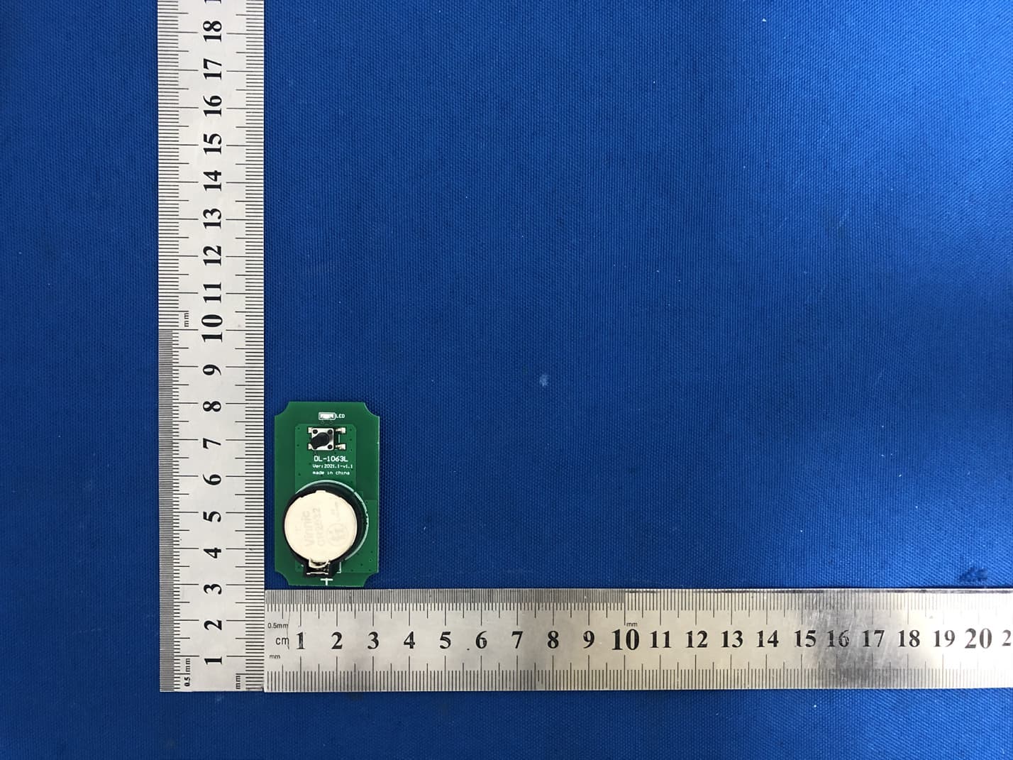
Click to zoom
Application Details
- Equipment Class
- DSC - Part 15 Security/Remote Control Transmitter
- Date of Grant
- Apr 28, 2021
- Application Purpose
- Original Equipment
- Date of Application
- Apr 28, 2021
- Equipment Note
- RF transmitter module
- Frequency Range
- 433.92000000 - 433.92000000
- Company
- Boil Boss LLC
- Country
- United States
Documents & Files
Document Text
Text extracted from the exhibit documents filed with the FCC. Open a document above to read the original.
Users Manual
User’s manual of DL-R1024L & DL-1063L low power consumption transmitter and receiver system DL-R1024L is an ultra-low power receiver module with sleep function, which is very suitable for battery powered places. DL-1063L is a matching remote controller. It adopts million code format to prevent repeated code. It is powered by CR2032 button battery. It is very suitable for daily use and convenient for users to replace batteries. Using method: 1. Install CR2032 button battery on the remote controller and CR123 column battery on the receiving module. Pay attention to the polarity of the battery. 2. Connect the output end to be controlled at the out end of the receiving module, and install the inching safety key at the CZ1 end. When the safety key is not pressed, the power supply of the module is disconnected, and the module can enter the next step only when the safety key is pressed. 3. Manual output: press and hold the safety key, and then press the manual key on the top of the module, the out end will output 0.25 seconds, each time the key is only output once, the key time is very long, and only output 0.25 seconds. 4. Receiving switch on: press and hold the security button, and then press the learning button in the middle of the module for 3 seconds, the indicator will flash once, the module is in standby mode, and then it can enter the learning or remote control operation; in the power on mode, press and hold the learning button for 3 seconds, the indicator will flash twice, the module is in deep sleep state, at this time, it can not be operated remotely, and the power consumption of the receiving module is close to zero At 0. 5. Remote control learning: in the power on state, press the learning key once, and the indicator light will be on for a long time. Press the remote control key again, and the indicator light will flash twice continuously, indicating that the learning is successful. Later, you can use the remote control to operate. This receiver only remembers one remote control code. When learning a new remote control again, the code learned previously will be cleared automatically. 6. Remote control output: in standby mode, press the remote control button, the receiving module will output 0.25 seconds, and press the remote control for a long time, it will only output 0.25 seconds. 7. Receiving module timing sleep: when the receiving module is in standby mode, it will automatically enter deep sleep after 8 hours of no operation. Next time, it needs to manually press the learning button to resume the standby mode. DL-1063L Parameter: 1. Power supply: CR2032 button battery, standard 3VDC. 2. Frequency: 433.92mhz. 3. Coding: millions of coding formats in the same format as EV1527. DL-R1024L technical parameters: 1. Power supply: CR123 column dry battery, standard 3VDC. 2. Frequency: 433.92mhz. 3. Deep sleep power consumption: 0.1uA. 4. Standby power consumption: 890uA, MCU and receiving module are in full operation. 5. Single output time: 0.25 seconds FCC WARNING FCC Caution: Any changes or modifications not expressly approved by the party responsible for compliance could void the user's authority to operate this equipment. This device complies with Part 15 of the FCC Rules. Operation is subject to the following two conditions: (1) This device may not cause harmful interference, and (2) this device must accept any interference received, including interference that may cause undesired operation. This device and its antenna(s) must not be co-located or operating in conjunction with any other antenna or transmitter. 15.105 Information to the user. (b) For a Class B digital device or peripheral, the instructions furnished the user shall include the following or similar statement, placed in a prominent location in the text of the manual: Note: This equipment has been tested and found to comply with the limits for a Class B digital device, pursuant to part 15 of the FCC Rules. These limits are designed to provide reasonable protection against harmful interference in a residential installation. This equipment generates, uses and can radiate radio frequency energy and, if not installed and used in accordance with the instructions, may cause harmful interference to radio communications. However, there is no guarantee that interference will not occur in a particular installation. If this equipment does cause harmful interference to radio or television reception, which can be determined by turning the equipment off and on, the user is encouraged to try to correct the interference by one or more of the following measures: —Reorient or relocate the receiving antenna. —Increase the separation between the equipment and receiver. —Connect the equipment into an outlet on a circuit different from that to which the receiver is connected. —Consult the dealer or an experienced radio/TV technician for help. The device has been evaluated to meet general RF exposure requirement. The device can be used in portable exposure condition without restriction. Radiation Exposure Statement: This equipment complies with FCC radiation exposure limits set forth for an uncontrolled environment. This transmitter must not be co-located or operating in conjunction with any other antenna or transmitter. The availability of some specific channels and/or operational frequency bands are country dependent and are firmware programmed at the factory to match the intended destination. The firmware setting is not accessible by the end user. The final end product must be labelled in a visible area with the following: “Contains Transmitter Module FCC ID: 2AZQB-DL-1063L” Requirement per KDB996369 D03 2.2 List of applicable FCC rules List the FCC rules that are applicable to the modular transmitter. These are the rules that specifically establish the bands of operation, the power, spurious emissions, and operating fundamental frequencies. DO NOT list compliance to unintentional-radiator rules (Part 15 Subpart B) since that is not a con…
Text truncated - open the document above for the full version.
Cover Letter(s)
Boil Boss LLC 2021.04.27 Eurofins MET Labs 914 West Patapsco Avenue Baltimore, MD 21230 RE: CONFIDENTIALITY REQUEST FOR EUT NAME: RF transmitter module Trademark: N/A MODEL : DL-1063L FCC ID: 2AZQB-DL-1063L To Whom It May Concern: This letter serves as an official request for confidentiality under sections 0.457 and 0.459 of CFR 47. We have requested that the - Block Diagram - Schematics - Operational Description required to be submitted with this application be permanently withheld from public review. The above materials contain trade secrets and proprietary information not customarily released to the public. The public disclosure of these materials may be harmful to the applicant and provide unjustified benefits to its competitors. Please contact me if there is any information you may need. Sincerely, Client’s signature: Client’s name / title : Robert Lapeyre/Manager Contact information / address: 5115 River Road Harahan Louisiana 70123
Cover Letter(s)
Boil Boss LLC 2021.04.27 Eurofins MET Labs 914 West Patapsco Avenue Baltimore, MD 21230 RE: LETTER OF AGENT AUTHORIZATION To Whom It May Concern: We, the undersigned, hereby authorize Shenzhen BCTC Testing Co., Ltd to act on our behalf in all matters relating to application for equipment authorization, including the signing of all documents relating to these matters. We also hereby certify that no party to the application authorized hereunder is subject to the denial of benefits, including FCC benefits, pursuant to Section 5301 of the Anti-Drug Abuse Act of 1988, 21 U.S.C.853(a). This agreement expires one year from the current date. Sincerely, Client’s signature: Client’s name / title : Robert Lapeyre Contact information / address: 5115 River Road Harahan Louisiana 70123
Cover Letter(s)
Boil Boss LLC FCC Modular Approval Request Federal Communications Commission Equipment Authorization Division 7435 Oakland Mills Road Columbia, MD 21046 USA Date: 2021/04/27 Subject; Modular Transmitter Application Company name: Boil Boss LLC FCC ID: 2AZQB-DL-1063L Dear Sir/Madam, This letter includes the FCC application requirements for Modular Transmitter Approval Request for;- FCC KDB 996369 D01 ‘Module Certification Guide v02; and FCC KDB 996369 D03 OEM Manual v01 In accordance with 47CFR 15.212 Modular Transmitters and KDB 996369 D01 ‘Module Equip Auth Guide v02’. FCC ID: 2AZQB-DL-1063L has been examined against the following requirements. Requirement per 15.212 and KDB 996369 D01 Explanation from Grantee (do not write yes/no, but explain why product complies/how it is achieved) The radio elements must have the radio frequency circuitry shielded. Physical components and tuning capacitor(s) may be located external to the shield, but must be on the module assembly. No., The module is Limited Single Modular. The module must have buffered modulation/data inputs to ensure that the device will comply with Part 15 requirements with any type of input signal. Yes, This module have buffered modulation/data inputs . The module must contain power supply regulation on the module. Yes, The module have power supply regulation. The supply voltage is DC 3V. The module must contain a permanently attached antenna, or contain a unique antenna connector, and be marketed and operated only with specific antenna(s), per §§ 15.203, 15.204(b), 15.204(c), 15.212(a), 2.929(b). Yes, the module contains a permanently attached antenna The module must demonstrate compliance in a stand-alone configuration. No. The module is Limited Single Modular. The module must be labeled with its permanently affixed FCC ID label, or use an electronic display (see KDB Publication 784748). Yes,The host system have label in a visible area indicated the following texts: "Contains FCC ID: 2AZQB-DL-1063L The module must comply with all specific rules applicable to the transmitter, including all the conditions provided in the integration instructions by the grantee. Yes, This module meets the requirements of FCC part 15C(15.231).it specifically establish the Fundamental &Radiated Spurious Emission Measurement, Occupy Bandwidth, Dwell time Measurement Boil Boss LLC FCC Modular Approval Request The module must comply with RF exposure requirements Yes,This module complies with FCC RF radiation exposure limits set forth for an uncontrolled environment, The device has been evaluated to meet general RF exposure requirement. The device can be used in portable exposure condition without restriction." This module is designed to comply with the FCC statement, FCC ID is: 2AZQB- DL-1063L Integration Instructions for host product manufacturers The following items are submitted in support of application for Modular Transmitter FCC ID as noted above as required by the FCC KDB 996369 D03 OEM Manual v01. These items are provided as integration instructions for host product manufacturers (e.g., OEM instruction manual) to use when integrating a module in a host product. Any requirements that are not applicable to the Module are as indicated below. Summary of requirements and Checklist.Refer to the KDB for description of the complete requirements; KDB Ref Sect Requirements of KDB 996369 D03 User Manual Page Number reference 2.2 List of applicable FCC rules Page 4 2.3 Summarize the specific operational use conditions Page 4 2.4 Limited module procedures Page 4 2.5 Trace antenna designs Page 5 2.6 RF exposure considerations Page 5 2.7 Antennas Page 6 2.8 Label and compliance information Page 6 2.9 Information on test modes and additional testing requirements Page 6 2.10 Additional testing, Part 15 Subpart B disclaimer Page 7 Name: Robert Lapeyre Date: 2021/04/27 Title: Manager Signature of applicant :
External Photos
External Photos Antenna
ID Label/Location Info
Size:10*5mm FCC ID: 2AZQB-DL-1063L Label location
Internal Photos
External Photos
Test Report
No.:BCTC/RF-EMC-005 Page: 1 of 33 Edition:A.3 TEST REPORT Shenzhen BCTC Testing Co., Ltd. Report No.: BCTC2104554233E Applicant: Boil Boss LLC Product Name: RF transmitter module Model/Type Ref.: DL-1063L Tested Date: 2021-04-06 to 2021-04-13 Issued Date: 2021-04-13 Report No.: BCTC2104554233E No.:BCTC/RF-EMC-005 Page: 2 of 33 Edition:A.3 FCC ID: 2AZQB-DL-1063L The test report is effective only with both signature and specialized stamp.This result(s) shown in this report refer only to the sample(s) tested. Without written approval of Shenzhen BCTC Testing Co., Ltd, this report can’t be reproduced except in full.The tested sample(s) and the sample information are provided by the client. Product Name: RF transmitter module Trademark: N/A Model/Type Ref.: DL-1063L Prepared For: Boil Boss LLC Address: 5115 River Road Harahan Louisiana 70123 Manufacturer: Shenzhen DLEC Electronic Co., Ltd Address: 501, No. 9-1., Xintang Road, Xintian village, Fuhai street, Bao’an district., Shenzhen, China Prepared By: Shenzhen BCTC Testing Co., Ltd. Address: 1-2/F., Building B, Pengzhou Industrial Park, No.158, Fuyuan 1st Road, Tangwei, Fuhai Subdistrict, Bao'an District, Shenzhen, Guangdong, China Sample Received Date: 2021-04-06 Sample tested Date: 2021-04-06 to 2021-04-13 Issue Date: 2021-04-13 Report No.: BCTC2104554233E Test Standards FCC Part15.231 ANSI C63.10-2013 Test Results PASS Tested by: Approved by: Willem Wang/Project Handler Zero Zhou/Reviewer Report No.: BCTC2104554233E No.:BCTC/RF-EMC-005 Page: 3 of 33 Edition:A.3 TABLE OF CONTENT Test Report Declaration Page 1. VERSION ............................................................. 5 2. TEST SUMMARY ...................................................... 6 3. MEASUREMENT UNCERTAINTY ........................................ 7 4. PRODUCT INFORMATION AND TEST SETUP ............................ 8 4.1 Product Information ..................................................... 8 4.2 Test Setup Configuration ................................................ 8 4.3 Support Equipment ..................................................... 9 4.4 Channel List ........................................................... 9 4.5 Test Mode ............................................................. 9 5. TEST FACILITY AND TEST INSTRUMENT USED ........................ 10 5.1 Test Facility ........................................................... 10 5.2 Test Instrument Used .................................................. 11 6. CONDUCTED EMISSIONS ............................................. 13 6.1 Block Diagram Of Test Setup ............................................ 13 6.2 Limit ................................................................. 13 6.3 Test procedure ........................................................ 13 6.4 EUT operating Conditions ............................................... 13 6.5 Test Result ........................................................... 14 7. RADIATED EMISSIONS ............................................... 15 7.1 Block Diagram Of Test Setup ............................................ 15 7.2 Limit ................................................................. 16 7.3 Test procedure ........................................................ 17 7.4 EUT operating Conditions ............................................... 19 7.5 Test Result ........................................................... 20 8. BANDWIDTH TEST ................................................... 24 8.1 Block Diagram Of Test Setup ............................................ 24 8.2 Limit ................................................................. 24 8.3 Test procedure ........................................................ 24 8.4 EUT operating Conditions ............................................... 24 8.5 Test Result ........................................................... 25 9. CALCULATION OF AVERAGE FACTOR ................................ 26 10. DWEELL TIME ....................................................... 28 10.1 Block Diagram Of Test Setup .......................................... 28 10.2 Limit ................................................................ 28 10.3 Test procedure ....................................................... 28 10.4 Test Result .......................................................... 29 11. ANTENNA REQUIREMENT ............................................ 30 11.1 STANDARD REQUIREMENT .......................................... 30 11.2 EUT ANTENNA ...................................................... 30 Report No.: BCTC2104554233E No.:BCTC/RF-EMC-005 Page: 4 of 33 Edition:A.3 12. EUT PHOTOGRAPHS ................................................. 31 13. T TEST SETUP PHOTOGRAPHS ....................................... 32 (Note: N/A means not applicable) Report No.: BCTC2104554233E No.:BCTC/RF-EMC-005 Page: 5 of 33 Edition:A.3 1. VERSION Report No. Issue Date Description Approved BCTC2104554233E 2021-04-13 Original Valid Report No.: BCTC2104554233E No.:BCTC/RF-EMC-005 Page: 6 of 33 Edition:A.3 2. TEST SUMMARY The Product has been tested according to the following specifications: No. Test Parameter Clause No Results 1 Conducted Emission §15.207 N/A 2 Fundamental &Radiated Spurious Emission Measurement 15.209,15.231b PASS 3 Occupy Bandwidth 15.231c PASS 4 Dwell time 15.231a PASS 5 Antenna Requirement 15.203 PASS Report No.: BCTC2104554233E No.:BCTC/RF-EMC-005 Page: 7 of 33 Edition:A.3 3. MEASUREMENT UNCERTAINTY Where relevant, the following measurement uncertainty levels have been estimated for tests performed on the Product as specified in CISPR 16-4-2. This uncertainty represents an expanded uncertainty expressed at approximately the 95% confidence level using a coverage factor of k=2. No. Item Uncertainty 1 3m camber Radiated spurious emission(30MHz-1GHz) U=4.3dB 2 3m chamber Radiated spurious emission(1GHz-18GHz) U=4.5dB 3 3m chamber Radiated spurious emission(18GHz-40GHz) U=3.34dB 4 Conducted Ad…
Text truncated - open the document above for the full version.
Test Setup Photos
Report No.: BCTC2104554233E No.:BCTC/RF-EMC-005 Page: 32 of 33 Edition:A.3 13. T TEST SETUP PHOTOGRAPHS Radiated Measurement Photos
Contact Information
Applicant
Robert Lapeyre(Manager)
Technical Contact
Shenzhen BCTC Testing Co., Ltd.Alan Mei
[email protected]86-755-36882589
1-2/F., Building B, Pengzhou Industrial Park, · Bao'an District, Shenzhen, Guangdong · China
Test Firm
Shenzhen BCTC Testing Co., Ltd.Sally He
[email protected]15999690624
Technical Specifications
| # | Rule Parts | Frequency Range | Power Output |
|---|---|---|---|
| 1 | 15.231 | 433.92 MHz - 433.92 MHz | - |