2AZVB-FF1108-1CWLAFish Finder
Jinhua Lucky ET Manufacturer Co., Ltd.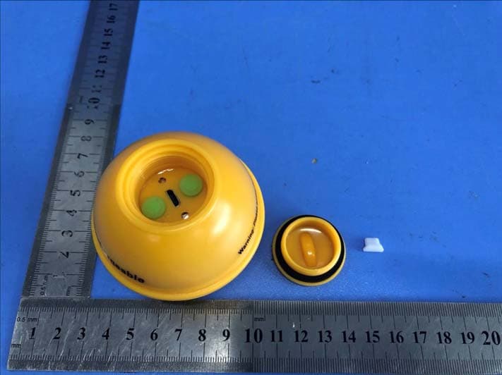
Click to zoom
Application Details
- Equipment Class
- DSC - Part 15 Security/Remote Control Transmitter
- Date of Grant
- May 19, 2021
- Application Purpose
- Original Equipment
- Date of Application
- May 19, 2021
- Equipment Note
- Fish Finder
- Frequency Range
- 433.92000000 - 433.92000000
- Country
- China
Documents & Files
Document Text
Text extracted from the exhibit documents filed with the FCC. Open a document above to read the original.
Users Manual
http://www.goodluckycn.com FF1108-1CWLA fish finder Wireless Mode Operations Manual When FF1108-1CWLA powers on, the will temporarily display on screen last for 5seconds.Then will show ,From this menu, use the arrow keys to select either Start-Up, Simulator. FF1108-1CWLA Fish Finder Wireless Mode Operations Manual Thank you for choosing FF1108-1CWLA fish finder. The FF1108-1CWLA has two different user modes:WIRELESS /TRANSDUCER Use the User Mode menu choice to change between these two user modes. WIRELESS:This user mode allows you to operate the FF1108-1CWLA with the wireless sonar sensor. When signal indicator is displayed on the screen, the unit is in Wireless mode. Wireless sonar sensor signal connect indicator Display View The FF1108-1CWLA displays underwater information in an easy- to-understand format. The top of the display corresponds to the water surface at the transducer, and the bottom of the display corresponds to the Depth Range automatically selected for the current water depth. The Bottom Contour varies as the depth under the boat changes. Digital readouts provide precise information for depth, fish and water temperature. As the boat moves, terrain and bottom composition variations are displayed. Fish, baitfish and the rmoclines (underwater Press the POWER-MENU key last for 5 seconds to power FF1108-1CWLA on. Press and hold the POWER-MENU key until the unit shuts down to power off. Powering ON and OFF Fish Alarm— Press the POWER-MENU key until FISH ALARM appears. Select Off for no fish alarm, or one of the following symbols to set the alarm. An alarm will sound when the FF1108-1CWLA detects fish that correspond to the alarm setting. Fish Alarm will only sound if Fish ID+ is also set to On. Make sure press the POWER-MENU key until FISH ICON appears. Select either Off to view “raw” sonar returns, or On to view Fish symbols. Fish ICON uses advanced signal processing to interpret sonar returns, and will display a Fish Symbol when very selective requirements are met. Make sure press the POWER-MENU key UNITS appears. UNITS selects the UNITS of (M/°C、FT/°C、M/°F、FT/°F) Units Fish Icon A select number of possible fish returns will be displayed with their associated depth. (On, Off) SPECIFICATIONS Maintenance Follow these simple procedures to ensure your FF1108-1CWLA continues to deliver top performance. If the unit comes into contact with salt spray, wipe the affected surfaces with a cloth dampened in fresh water. Do not use a chemical glass cleaner on the less-this may cause cracking in the lens. When cleaning the LCD protective lens, use a chamois and non-abrasive, mild cleaner. Do not wipe while dirt or grease is on the lens. Be careful to avoid scratching the lens. Never leave the unit in a closed car or trunk - the extremely high temperatures generated in hot weather can damage the electronics. After using the Wireless sonar sensor in salt water, wipe the affected surfaces with a cloth dampened with fresh water. The Wireless sonar sensor Cuprum-switch must be rinsed with fresh water after exposure to salt water prevent corrosion. If your Wireless sonar sensor remains out of the water for a long period of time, it may take some time to wet it when returned to the water. Small air bubbles can cling to the surface of the Wireless sonar sensor and interfere with proper operation. Wipe the face of the Wireless sonar sensor with a wet cloth to remove them. Wireless sonar sensor Maintenance Wireless sonar sensor is placed back in the water and reception is regained. will be displayed until the seconds, the 1) The Wireless sonar sensor uses line -of- sight wireless technology. If objects are placed between the FF1108-1CWLA and the Wireless sonar sensor, reception may be lost. 2) The Wireless sonar sensor depth range is 3 to 147 feet (0.7 to 45 meters). Erratic readings may occur in water that is shallower than 3 feet. In addition, because of the nature of sonar, this product is not intended for use in swimming pools or small enclosed bodies of water. 3) Reeling the Wireless sonar sensor too fast can cause loss of signal and the screen will freeze. 4) Check the buoyant balance between the Wireless sonar sensor and your tackle; over 0.2 ounce will submerge the Wireless sonar sensor, causing signal loss. 5) The Wireless sonar sensor may not obtain its maximum RF distance of 200 feet unless the water is smooth. Waves or chop may reduce the RF range significantly. 2.When in very shallow water, I get gaps in the bottom reading and inconsistent digital depth indication. The Wireless sonar sensor will work reliably in water 3 feet (0.7 meters) or deeper. The depth is measured from the Wireless sonar sensor. A Wireless sonar sensor to FF1108-1CWLA distance of greater than 200ft may cause intermittent screen display. Excessively rough water may cause the Wireless sonar sensor to submerge, again losing contact. Fish finder power:.........3.7 Volt rechargeable lithium battery Wireless sonar sensor power :............3.7V Lithium Battery Display Type ..............................320x240 TFT color LCD Depth Capability..........................................3-147 feet (0.7 – 45 meters) 。 Sonar Beam Angle................................................90 Sonar Operating Frequency ..............................125kHz Operational Wireless Frequency..................... 433.92MHZ Operational Range ........................ 200feet (60meters) . ·Use Start-Up for on the water use. ·Use Simulator for learning how to use the system with simulated sonar data; access Simulator by pressing the Down Arrow Key once NOTE: Each time the POWER-MENU key is pressed, the backlight momentarily illuminates for easy viewing at night. Adjust the LIGHT menu setting to keep the backlight on. temperature changes) are displayed when detected. Underwater conditions vary greatly, so some experience and interpretation is needed to realize all the benefits of the FF1108-1CWLA use the picture as a guide to the most common condit…
Text truncated - open the document above for the full version.
Cover Letter(s)
Jinhua Lucky ET Manufacturer Co., Ltd. Add: No.1966 Cuntong Road, Jindong Industrial Zone, Jinhua City, Zhejiang Province, China Date: 2021-5-11 FCC ID: 2AZVB-FF1108-1CWLA Dear Sir/Madam, We, Jinhua Lucky ET Manufacturer Co., Ltd. Hereby declares the following statement for Federal Communications Commission, PCB board, circuit, structure and internal of these model(s) are the same, Only model number is different for these model: Product name: Fish Finder Model no.: FF1108-1CWLA, FF1108-1CW, FF1108-1C(LA), FF(C)W1108-1, FFW718(LA), FF718Li(C)-W(LA), FF718Li(C)(D)(LA), FF918-CWS, FF918-C100W(D)S, FF918-C180W(D)S, FF918-CWLS, FF916, FF3309, FF205, FF206, FF207 Sincerely, Name/Title : Sitar Liu/ Manager Company: Jinhua Lucky ET Manufacturer Co., Ltd. Address: No.1966 Cuntong Road, Jindong Industrial Zone, Jinhua City, Zhejiang Province, China Phone: 19957915636 Fax: 0579 - 82081587 E - Mail: [email protected]
Cover Letter(s)
CONFIDENTIALITY REQUEST for Certification Service in USA Federal Communication Commission Equipment Authorization Division, Application Processing Branch 7435 Oakland Mills Road Columbia, MD 21046 Date:<2021-5-11> Pursuant to Paragraphs §0.457 and 0.459 of the Commission’s Rules (47 C.F.R.) and Section §552(b)(4) of the Freedom of Information Act, we requests confidentiality for the following products: FCC ID Model name 2AZVB-FF1108-1CWLA FF1108-1CWLA For the product stated above, we request that the following information be held confidential; Exhibits Long-Term Confidentiality Short-Term Confidentiality Short-Term Confidentiality Days External Photos Internal Photos Block Diagram Schematics Test Setup Photos User’s Manual Parts List Tune Up Operational Descriptions The long-term confidentiality exhibits contain our trade secrets and proprietary information that could be of benefit to our competitors. The short-term confidentiality on the basis of ensuring that business sensitive information remains confidential until the actual marketing of our new device. If you have any questions, please feel free to contact me at the address shown below. Sincerely, Name/Title : Sitar Liu / Manager Company: Jinhua Lucky ET Manufacturer Co., Ltd. Address: No.1966 Cuntong Road, Jindong Industrial Zone, Jinhua City, Zhejiang Province, China Phone: 19957915636 Fax: 0579 - 82081587 E - Mail: [email protected]
Cover Letter(s)
Jinhua Lucky ET Manufacturer Co., Ltd. No.1966 Cuntong Road, Jindong Industrial Zone, Jinhua City, Zhejiang Province, China Federal Communications Commission Authorization and Evaluation Division Equipment Authorization Branch 7435 Oakland Mills Road Columbia, MD 21046 2021-5-11 To whom it may concern: We, Jinhua Lucky ET Manufacturer Co., Ltd. the undersigned, hereby authorize Eurofins Product Service GmbH to act on our behalf in all matters relating to applications for equipment authorization FCC ID: 2AZVB-FF1108-1CWLA including the signing of all documents related to these matters. Any and all acts carried out by Eurofins Product Service GmbH on our behalf shall have the same effect as acts of our own. We also hereby certify that no party to this application is subject to a denial of benefits, including FCC benefits, pursuant to Section 5301 of the Anti-Drug Abuse Act of 1988, 21 U.S.C. 862. Sincerely, Name/Title : Sitar Liu / Manager Company: Jinhua Lucky ET Manufacturer Co., Ltd. Address: No.1966 Cuntong Road, Jindong Industrial Zone, Jinhua City, Zhejiang Province, China Phone: 19957915636 Fax: 0579 - 82081587 E - Mail: [email protected]
External Photos
FCC ID: 2AZVB-FF1108-1CWLA TB-RF-074-1.0 Appendix III EUT External Photographs Photo 1 Appearance of EUT Photo 2 Appearance of EUT FCC ID: 2AZVB-FF1108-1CWLA TB-RF-074-1.0 Photo 3 Appearance of EUT Photo 4 Appearance of EUT FCC ID: 2AZVB-FF1108-1CWLA TB-RF-074-1.0 Photo 5 Appearance of EUT
ID Label/Location Info
FCC ID: 2AZVB-FF1108-1CWLA TB-RF-074-1.0 Appendix IFCC ID Label Size for the label: 10mm X 10mm FCCID:2AZVB-FF1108-1CWLA Model:FF1108-1CWLA FCC ID: 2AZVB-FF1108-1CWLA TB-RF-074-1.0 Appendix II ID Label Location ID LOCATION
Internal Photos
FCC ID: 2AZVB-FF1108-1CWLA TB-RF-074-1.0 Appendix IV EUT Internal Photographs Photo 6 Internal of PCB Photo 7 Appearance of PCB Antenna FCC ID: 2AZVB-FF1108-1CWLA TB-RF-074-1.0 Photo 8 Appearance of PCB&Battery Photo 9 Appearance of PCB FCC ID: 2AZVB-FF1108-1CWLA TB-RF-074-1.0 Photo 10 Appearance of PCB Photo 11 Appearance of PCB FCC ID: 2AZVB-FF1108-1CWLA TB-RF-074-1.0 Photo 12 Appearance of PCB
Test Report
Shenzhen Toby Technology Co., Ltd. Report No.: TB-FCC179485 Page: 1 of 31 TB-RF-074-1.0 1 A/F., Building.6, Rundongsheng Industrial Zone, Longzhu, Xixiang, Bao’an, Shenzhen, Guangdong, China Tel: +86 75526509301 Fax: +86 75526509195 FCC Radio Test Report FCC ID: 2AZVB-FF1108-1CWLA Report No. : TB-FCC179485 Applicant : Jinhua Lucky ET Manufacturer Co., Ltd. Equipment Under Test (EUT) EUT Name : Fish Finder Model No. : FF1108-1CWLA Serial Model No. : FF1108-1CW, FF1108-1C(LA), FF(C)W1108-1, FFW718(LA), FF718Li(C)-W(LA), FF718Li(C)(D)(LA), FF918-CWS, FF918-C100W(D)S, FF918-C180W(D)S, FF918-CWLS, FF916, FF3309, FF205, FF206, FF207 Brand Name : LUCKY, LUCKYLAKER Receipt Date : 2021-03-25 Test Date : 2021-03-25 to 2021-05-10 Issue Date : 2021-05-10 Standards : FCC Part 15, Subpart C (15.231(e) Test Method : ANSI C63.10:2013 Conclusions : PASS In the configuration tested, the EUT complied with the standards specified above, The EUT technically complies with the FCC requirements Test/Witness Engineer : Seven Wu Engineer Supervisor : Ivan Su Engineer Manager : Ray Lai This report details the results of the testing carried out on one sample. The results contained in this test report do not relate to other samples of the same product. The manufacturer should ensure that all products in series production are in conformity with the product sample detailed in the report. Report No.: TB-FCC179485 Page: 2 of 31 TB-RF-074-1.0 Contents CONTENTS ............................................................................................................................................. 2 1. GENERAL INFORMATION ABOUT EUT ............................................................................. 5 1.1 Client Information ................................................................................................................. 5 1.2 General Description of EUT (Equipment Under Test) ................................................... 5 1.3 Block Diagram Showing the Configuration of System Tested ...................................... 6 1.4 Description of Support Units .............................................................................................. 6 1.5 Description of Test Mode .................................................................................................... 6 1.6 Description of Test Software Setting .............................................................................. 7 1.7 Measurement Uncertainty ................................................................................................ 7 1.8 Test Facility ........................................................................................................................ 8 2. TEST SUMMARY ....................................................................................................................... 8 3. TEST EQUIPMENT .................................................................................................................... 9 4. CONDUCTED EMISSION TEST ........................................................................................... 10 4.1 Test Standard and Limit .................................................................................................... 10 4.2 Test Setup ........................................................................................................................... 10 4.3 Test Procedure ................................................................................................................... 10 4.4 Test Data ............................................................................................................................. 11 5. RADIATED EMISSION TEST ................................................................................................ 12 5.1 Test Standard and Limit .................................................................................................... 12 5.2 Test Setup ........................................................................................................................... 13 5.3 Test Procedure ................................................................................................................... 15 5.4 Deviation From Test Standard ......................................................................................... 15 5.5 EUT Operating Condition ................................................................................................. 15 5.6 Test Data ............................................................................................................................. 15 6. BANDWIDTH ............................................................................................................................ 16 6.1 Test Standard and Limit .................................................................................................... 16 6.2 Test Setup ........................................................................................................................... 16 6.3 Test Procedure ................................................................................................................... 16 6.4 EUT Operating Condition ................................................................................................. 16 6.5 Test Data ............................................................................................................................. 16 7. RELEASE TIME MEASUREMENT ....................................................................................... 17 7.1 Test Standard and Limit .................................................................................................... 17 7.2 Test Setup ........................................................................................................................... 17 7.3 Test Procedure ................................................................................................................... 17 7.4 EUT Operating Condition ...................…
Text truncated - open the document above for the full version.
Test Setup Photos
FCC ID: 2AZVB-FF1108-1CWLA TB-RF-074-1.0 Appendix V EUT Test Photographs 15C Test Setup Photo of Setup for Radiated Emission (Above 1 GHz) Photo of Setup for Radiated Emission (Below 1 GHz) FCC ID: 2AZVB-FF1108-1CWLA TB-RF-074-1.0 Photo of Setup for Conducted Emission -----END OF REPORT-----
Contact Information
Applicant
Sitar Liu(Manager)
Test Firm
Shenzhen Toby Technology Co., Ltd.Ray Lai
Technical Specifications
| # | Rule Parts | Frequency Range | Power Output |
|---|---|---|---|
| 1 | 15.231(e) | 433.92 MHz - 433.92 MHz | - |