2AZVW5282011Digital Weather Forecaster
Lifetime Brands, Inc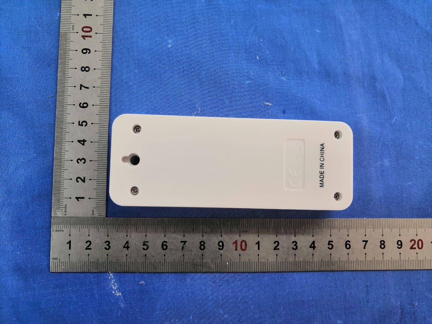
Click to zoom
Application Details
- Equipment Class
- DSC - Part 15 Security/Remote Control Transmitter
- Date of Grant
- Jun 02, 2021
- Application Purpose
- Original Equipment
- Date of Application
- Jun 02, 2021
- Equipment Note
- Digital Weather Forecaster
- Frequency Range
- 433.92000000 - 433.92000000
- Company
- Lifetime Brands, Inc
- Country
- United States
Documents & Files
Document Text
Text extracted from the exhibit documents filed with the FCC. Open a document above to read the original.
Users Manual
Digital Weather Forecaster 5282011 INSTRUCTION MANUAL Thank you for purchasing a Taylor digital weather forecaster. This weather instrument is an example of superior design and craftsmanship. Please read instructions thoroughly to ensure that you have the full benefit of all the unit’s features. Keep these instructions handy for future reference. BATTERY INSTALLATION AND INITIAL SET UP The weather forecaster can operate on either two (2) 1.5V AAA batteries (not included) or USB cord (included). •The battery compartment is located on the back of the weather forecaster. Insert 2 AAA batteries into the battery compartment according to the “+” and “-“ polarity symbols. Replace the battery compartment cover. OR Insert the small end of the USB cord into the port located on the back of the weather forecaster. Then plug the USB (larger end) into a wall outlet converter and into the wall outlet. Please note, you will need to use your own wall outlet converter to plug the cord into. •The weather forecaster will beep and the LCD will light up. •Open the battery compartment located on the front of the wireless sensor. Insert two (2) AAA batteries according to the “+” and “-“ polarity symbols. Replace the battery compartment cover. •The weather forecaster will begin connecting to the wireless sensor. The outdoor temperature and humidity will display a flashing “--.-“. •Once the weather forecaster and wireless sensor have been successfully connected, the outdoor temperature and humidity readings will be displayed on the forecaster along with the selected Channel number (1, 2, or 3). To change channels on the wireless sensor, open the battery compartment and manually switch to the desired channel. •If the wireless sensor does not pair with the forecaster within 3 minutes, “--.-“ will appear on the display. Check the batteries on the wireless sensor and if there is any source of interference nearby (for example, computer monitors, television sets, etc). • To manually pair the wireless sensor and weather forecaster, press and hold the sCHANNEL button located on the back of the forecaster for 3 seconds and “--.-“ appears on the display. Press the TX button located in the battery compartment of the wireless sensor. The forecaster will beep and the receive the readings from the wireless sensor. Replace the battery compartment cover on the wireless sensor. Change the batteries in the weather forecaster when the battery symbol appears on the indoor values display. Change the batteries in the wireless sensor when the battery symbol appears on the outdoor values display. When batteries are changed, the connection between weather forecaster and wireless sensor(s) must be restored so always insert new batteries into both units or start a manual transmitter search. NOTE: The LCD display will automatically dim while using battery power to conserve energy, press the LIGHT button on the back of the forecaster to illuminate the LCD. The LCD display will remain fully lit while being powered by the USB cord. Do not mix old and new batteries. Do not mix alkaline, standard (carbon-zinc) or rechargeable (nicad, ni-mh, etc.) batteries. NOTE: Please recycle or dispose of batteries per local regulations. WARNING: Batteries may pose a choking hazard. As with all small items, do not let children handle batteries. If swallowed, seek medical attention immediately. PRECAUTION: Do not dispose of batteries in fire. Batteries may explode or leak. Remove the batteries if the scale will not be used for a long period of time DESCRIPTION OF PARTS A1: Day of the Week A2: Weather Forecast A3: Barometric Pressure A4: Forecaster Battery Icon A5: Indoor Temperature A6: Indoor Humidity A7: Outdoor Temperature A8: Wireless sensor battery icon A9: Outdoor Humidity A10: Date, Month/Day A11: Time B1: Control Buttons (LIGHT, sCHANNEL, SET/ AL SET, t°F/°C/ RCC, MAX/MIN) B2: Battery Compartment B3: Reset Button B4: USB port (Type-C input plug) B5: Support Foot C1: Wall Mounting Hole C2: LED Index C3: Battery Compartment C4: Channel Switch (1-2-3) C5: TX Button RADIO SIGNAL RECEPTION Once the weather forecaster receives the outdoor temperature and humidity readings, it will scan the RCC frequency signal and the RCC symbol will flash on the display. During the Radio Control receiving mode, only the tF/°C/RCC button will operate. All other button operations will not function. When the time code is successfully received (this will take between 2 – 12 minutes), the radio controlled time and RCC symbol are steadily displayed on the LCD and all of the control buttons are activated again. To manually start signal reception, press and hold the t°F/°C/RCC button for 3 seconds. The RCC symbol will flash. To stop searching radio signal during Radio Control reception, press the t°F/°C/RCC button again and the DCF symbol disappears. The RCC reception always occurs hourly between 2:00am and 5:00am. If the reception is not successfully received until 5:00am, the next reception will take place again at 2:00am. If the clock cannot detect the RCC signal due to disturbances, transmitting distance, etc., the time can be set manually. The RCC symbol disappears and the clock will work as a normal quartz clock (see Manual Settings). If RCC is not needed, the function can be turned off (see Manual Settings). NOTE: It is recommended to have a minimum distance of 5 to 6.5ft. (1.5 to 2 meters) to all sources of interference, such as televisions or computer monitors. Radio reception is weaker in rooms with concrete walls (e.g.: in cellars) and in offices. In such extreme circumstances, place the system close to a window. During night time, the atmospheric interference is usually less severe and reception is possible in most cases. A single daily reception is adequate to keep the accuracy deviation under 1 second. There are four different reception symbols: MANUAL TIME SETTING Press and hold SET/AL SET for 3 seconds while in normal mode to enter the setting mode. The Time Zone st…
Text truncated - open the document above for the full version.
Cover Letter(s)
2021-03-29 FEDERAL COMMUNICATIONS COMMISSIONS Authorization and Evaluation Division 7435 Oakland Mi lls Road Columbia, MD 21046 Subject: Confidentiality Request regarding application for certification of FCC ID: 2AZVW5282011 In accordance with Sections 0.457 and 0.459 of the Commission’s Rules, Lifetime Brands, Inc hereby requests long-term confiden tial treatment of information accompanying this application as outlined below: Block Diagram Schematics Operation Description The above materials contain proprietary and confidential information not customarily released to the public. The public disclosure of these materials provides unjustified benefits to its competitors in the market. Sincerely, Company Name: Lifetime Brands, Inc Add: 2311 W. 22nd Street, Suite 200 Oak Brook, ILLINOIS 60523 USA Tel: 630 468 5247 Fax: N/A E-mail: [email protected] FCC Confidential Authorization Sincerely Yours, QA-FR-172-A Signature: Typed or Printed Name: Jeffr ey Koon Title: Director of Engineering-Taylor Division
External Photos
EXHIBIT A - EUT EXTERNAL PHOTOGRAPHS
ID Label/Location Info
20mm Digital Weather Forecaster Model : 5282011 FCC ID: 2AZVW5282011 8mm
Internal Photos
EXHIBIT B - EUT INTERNAL PHOTOGRAPHS Spring Antenna
Test Report
FCC PART 15.231 TEST REPORT For Lifetime Brands, Inc 2311 W. 22nd Street, Suite 200 Oak Brook, ILLINOIS 60523 USA FCC ID: 2AZVW5282011 Report Type: Amended Report Product Type: Digital Weather Forecaster Project Engineer: Miller Xie Report Number: RSHD210329001-00B Report Date: 2021-06-03 Reviewed By: Oscar Ye EMC Manager Prepared By: Bay Area Compliance Laboratories Corp. (Kunshan) No.248 Chenghu Road, Kunshan, Jiangsu province, China Tel: +86-0512-86175000 Fax: +86-0512-88934268 www.baclcorp.com.cn Bay Area Compliance Laboratories Corp. (Kunshan) Report No.: RSHD210329001-00BM1 FCC Part 15.231 Page 2 of 24 TABLE OF CONTENTS REPORT REVISION .................................................................................................................................................... 3 GENERAL INFORMATION ....................................................................................................................................... 4 PRODUCT DESCRIPTION FOR EQUIPMENT UNDER TEST (EUT) ..................................................................................... 4 OBJECTIVE ................................................................................................................................................................... 4 RELATED SUBMITTAL(S)/GRANT(S) ............................................................................................................................. 4 TEST METHODOLOGY .................................................................................................................................................. 4 MEASUREMENT UNCERTAINTY .................................................................................................................................... 5 TEST FACILITY ............................................................................................................................................................. 5 SYSTEM TEST CONFIGURATION .......................................................................................................................... 6 JUSTIFICATION ............................................................................................................................................................. 6 EUT EXERCISE SOFTWARE .......................................................................................................................................... 6 EQUIPMENT MODIFICATIONS ....................................................................................................................................... 6 SUPPORT EQUIPMENT LIST AND DETAILS .................................................................................................................... 6 EXTERNAL I/O CABLE .................................................................................................................................................. 6 BLOCK DIAGRAM OF TEST SETUP ................................................................................................................................ 7 SUMMARY OF TEST RESULTS ............................................................................................................................... 8 TEST EQUIPMENT LIST ........................................................................................................................................... 9 FCC§15.203 - ANTENNA REQUIREMENT ............................................................................................................ 10 APPLICABLE STANDARD ............................................................................................................................................ 10 ANTENNA CONNECTED CONSTRUCTION .................................................................................................................... 10 FCC §15.205, §15.209, §15.231 (E) - RADIATED EMISSIONS ............................................................................. 11 APPLICABLE STANDARD ............................................................................................................................................ 11 EUT SETUP ................................................................................................................................................................ 11 EMI TEST RECEIVER SETUP ....................................................................................................................................... 12 TEST PROCEDURE ...................................................................................................................................................... 12 CORRECTED AMPLITUDE & MARGIN CALCULATION ................................................................................................. 12 TEST RESULTS SUMMARY .......................................................................................................................................... 13 TEST DATA ................................................................................................................................................................ 13 FCC §15.231(E) - DEACTIVATION TESTING ...................................................................................................... 18 APPLICABLE STANDARD ............................................................................................................................................ 18 EUT SETUP ................................................................................................................................................................ 18 TEST PROCEDURE ...................................................................................................................................................... 18 TEST DATA ................................................................................................................................................................ 18 FCC §15.231(C) - 20DB EMISSION BANDWIDTH TESTING ...…
Text truncated - open the document above for the full version.
Test Setup Photos
EXHIBIT C - TEST SETUP PHOTOGRAPHS RadiatedEmissions -Front View (Below 1GHz) RadiatedEmissions - Rear View (Above 1GHz)
Contact Information
Applicant
Jeffrey Koon(Director of Engineering-Taylor Division)
Test Firm
Bay Area Compliance Laboratories Corp. (Kunshan)Mr. John Chan
[email protected]+86 0512 86175000
Technical Specifications
| # | Rule Parts | Frequency Range | Power Output |
|---|---|---|---|
| 1 | 15.231(e) | 433.92 MHz - 433.92 MHz | - |