2AZX2-BV00000115W Car Wireless Charging Module
An Energy Technology Co., Ltd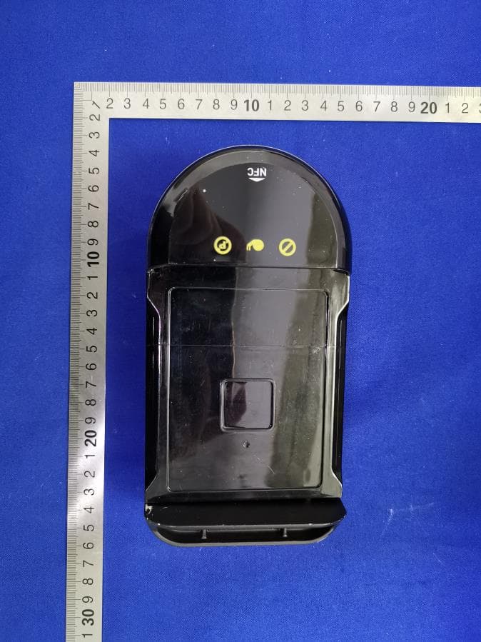
Click to zoom
Application Details
- Equipment Class
- JAB - Part 15 Class B Digital Device
- Date of Grant
- Jul 07, 2021
- Application Purpose
- Original Equipment
- Date of Application
- Jul 05, 2021
- Equipment Note
- 15W Car Wireless Charging Module
- Country
- China
Documents & Files
Document Text
Text extracted from the exhibit documents filed with the FCC. Open a document above to read the original.
Users Manual
User Manual Product Overview Product Introduction: This product is installed in the dashboard as part of the electric assisted bicycle, See the above picture. When the user is actually using the bicycle, this product can be used for swiping the card and charging the mobile phone, and when using time, the user will not touch the product and should keep a certain distance, at least 20cm. I.More introduction This product offers a configurable charging mode that supports 15W.15W power supply meets WPC QI standard RX.Supports foreign body detection, if there is a foreign body, as a metal conductive material, between the transmitter and the receiver, the transmitter is off. Place the mobile phone in the wireless charging tray, charge the mobile phone, and stop charging after removing the mobile phone. Magnetic card into the NFC induction area when the card operation! II. Product parameters Name: Vehicle-mounted 15W wireless charging seat Model: W015CN - 01 / W015CN - 10 / W015CN - XX Color: black Input voltage: DC 16V~20V Input current: 2A(Max) Output power: 15W(Max) III. characteristics ○ Meet the WPC QI standard ○ Support foreign body detection ○ Operating temperature range: 0-35 deGC.Humidity range: 20%-80%. ○ Storage temperature range: -20 -- 70 deGC.Humidity range: 5%-90%. ○ RoHS compliance IIII. PRODUCT SPECIFICATIONS Intended Use/Category Wireless Charging H-Field Strength 50.21 dBuA/m@3m distance Frequency band(MHz) 110KHz-145KHz Modulation ASK Antenna type Coil Antenna Duty cycle(%) / Intended Use/Category NFC H-Field Strength 17.41 dBuA@3m distance Frequency band(MHz) 13.56MHz Modulation ASK Antenna type Coil Antenna Duty cycle(%) / IIIII. functional description The wireless charging input terminal VCC is connected to the 18V direct current. After the voltage is lowered by the BUCK circuit constituted by MOS tube Q1(RU30J30) and L3, it works in the full bridge circuit constituted by Q2(RU30J30) and Q3(RU30J30).The IC(CPS8100) sends a drive signal to control the Q2(RU30J30) upper and Q3(RU30J30) lower tubes and Q2(RU30J30) lower tubes and Q3(RU30J30) upper tubes to conduct alternately, so that an alternating voltage is obtained on the coil!Then through the electromagnetic induction to the receiving coil to get the voltage!The IC(CPS8100) detects current through resistor R9! NFC Product Overview Introduction The FM17550 is a highly integrated Transceiver IC for Contactless communication at 13.56MHz. The FM17550 Transceiver IC support Reader/Writer mode supporting ISO/IEC 14443A/B protocal. The FM17550’s internal transmitter part is able to drive a reader/writer antenna designed to communicate with ISO/IEC14443A/B cards and transponders without additional active circuitry. The receiver part provides a robust and efficient implementation of a demodulation and decoding circuitry for signals from ISO/IEC14443A/B compatible cards and transponders. The digital part handles the complete ISO/IEC 14443A/B framing and error detection. The FM17550 supports ISO/IEC14443A cards and transponders with transfer speeds from 106kbit/s to 424kbit/s in both directions. And can supports all layers of the ISO/IEC14443B reader/writer communication scheme, and provided that stardardized protocols, e.g. like ISO/IEC 14443-4 and/or ISO/IEC 14443B anticollision are correctly implemented. Features Supports ISO/IEC 14443A/M1 reader/writer mode Supports ISO/IEC 14443B reader/writer mode ISO/IEC14443A 106kbit/s and higher transfer speed at 212kbit/s and 424kbit/s Typical operating distance in reader/writer mode for communication to a ISO/IEC 14443A card up to 50mm (depending on the antenna size and tuning) Supports host interfaces SPI interface up to 10Mbit/s I2C interface up to 400kbit/s in Fast Mode , and up to 3400kbit/s in High Speed Mode Serial UART in different transfer speeds up to 1228.8kbit/s, framing according to the RS232 interface with voltage levels according pad voltage supply Comfortable 64 byte send and receive FIFO-buffer Flexible interrupt modes Multiple low-power modes Soft power down mode Hard power down mode Deep power down mode (typical 1uA) Low Power external Card Detect (LPCD) at Reader/writer mode Programmable timer Internal oscillator to connect 27.12MHz quartz Wide voltage supply: 2.2V ~ 3.6V Dedicated transmitter voltage supply up to 5.5V Integrated CRC Co-processor Programmable I/O pins IMPORTANT SAFETY INSTRUCTIONS SAVE THESE INSTRUCTIONS WARNING When using this product, basic precautions should always be followed, including the following: • Read all the instructions before using the product. • To reduce the risk of injury, close supervision is necessary when the product is used near children. • DO NOT put fingers or hands into the product. • DO NOT use this product if the flexible power cord or output cable is frayed, has broken insulation, or any other signs of damage. • DO NOT allow anyone to ride the E-bike on his/her own unless he/she understands the proper operation and safety warnings. Assist new riders until they are comfortable with the basic operation of the E-bike. Meaning of Symbols and Marks This product conforms to the applicable EC Directives. WARNING-It is not permitted to dispose of this product as normal household waste. Ensure that the product is recycled in accordance with local legal requirements. Federal Communications Commission (FCC) Compliance Statement for USA This device complies with part 15 of the FCC rules. Operation is subject to the following two conditions: (1) This device may not cause harmful interference, and (2) this device must accept any interference received, including interference that may cause undesired operation. NOTE This equipment has been tested and found to comply with the limits for a Class B digital device, pursuant to part 15 of the FCC Rules. These limits are designed to provide reasonable protection against harmful interference in a residential installation. This equipment generates, uses and …
Text truncated - open the document above for the full version.
Cover Letter(s)
SCS-F019: Confidentiality Request Letter Page 1 of 2 Rev 7.0 775 Montague Expressway Milpitas, CA 95035 Tel: 408-526-1188 Fax: 408-526-1088 Email: [email protected] Website: https://www.cps.bureauveritas.com/ Confidentiality Request Letter Reason for Amendment (current / obsolete) Revision History Approved Date From To Initial Release (obsolete) 1.0 1.0 Nov-14-2006 Adding CFR 2.459 (obsolete) 1.0 2.0 August – 11 - 2008 Updated company template & Added text box (obsolete) 2.0 3.0 Jan-31-2012 Added IC confidentiality letter form (obsolete) 3.0 4.0 March-26-2015 Corrections to STC form. Added reference to KDB (obsolete) 4.0 5.0 Nov-19-2015 Updated company logo (current) 5.0 6.0 Jun-26-2019 Updated References and Contact Info 6.0 7.0 Aug-30-2020 SCS-F019: Confidentiality Request Letter Page 2 of 2 Rev 7.0 An Energy Technology Co., Ltd May 17, 2021 To: Federal Communications Commission Authorization and Evaluation Division 7435 Oakland Mills Road Columbia, MD 21046-1609 Cc: Bureau Veritas Consumer Products Services Inc. 775 Montague Expressway Milpitas, CA 95035 Subject: Confidentiality Request for FCC ID: 2AZX2-BV000001 Pursuant to CFR 47 sections 0.457 and 0.459, we respectfully request permanent confidential treatment of the following Exhibits accompanying this application be held confidential: Type of Confidentiality Requested Exhibit Short Term Permanent Block Diagram Short Term External Photos Short Term Permanent i Internal Photos Short Term Permanent Operational Description/ Theory of Operation Short Term Permanent Parts List Short Term Permanent Tune-Up Procedure Short Term Permanent Schematics Short Term Test Setup Photos Short Term Permanent i User’s Manual The above materials contain trade secrets and proprietary information not customarily released to the public. The public disclosure of these materials may be harmful to the applicant and provide unjustified benefits to its competitors. Permanent Confidentiality: The applicant requests the exhibits listed above as permanently confidential be permanently withheld from public review due to materials that contain trade secrets and proprietary information not customarily released to the public. Short-Term Confidentiality: To avoid premature release of sensitive information prior to marketing or release of the product to the public, the applicant requests the following documents contained in this certification application be temporarily withheld from public disclosure for an initial period of 45 or 180 days; or for a specified date of not to exceed 180 days from the Grant Date The applicant understands that disclosure of this application and all accompanying documentation will not be made before the date of the Grant for this application. Sincerely, Client’s signature: Client’s name & title: Bruce WU & purchasing manager Contact information / address: No. 139 Huaye Road, Jintan,Changzhou, Jiangsu, China i Permanent confidentiality may be requested in accordance with FCC KDB 726920
Cover Letter(s)
An Energy Technology Co., Ltd To:Bureau Veritas Consumer Product Services, Inc. Declaration Letter Dear Sir, For our business issue and marketing requirement, we would like to list 3 model numbers on the FCC certificates and reports, as following: Model No.: We declare that the difference of these is listed as below: Main Model No Serial Model No Difference W015CN-01 W015CN-10 / W015CN-XX They are all the same except appearance. Thank you! Signature: Printed name/title: Bruce WU / purchasing manager Tel: 13501911170 Fax: NA Address: No. 139 Huaye Road, Jintan,Changzhou, Jiangsu, China
External Photos
Page 1 of 4 External Photo Page 2 of 4 Page 3 of 4 Page 4 of 4
ID Label/Location Info
15W Car Wireless Charging Module Manufacturer:An Energy Technology Co.,Ltd FCC ID:2AZX2-BV000001 Manufacturer’s address: Modle : W015CN-XX Ratings:Input voltage : 16V DC~20V DC Input current 2A(max) No.139 Huaye Road,Jintan,Changzhou City,Jiangsu Prov. IC: 27297-AN00000001 15W Car Wireless Charging Module Manufacturer:An Energy Technology Co.,Ltd FCC ID:2AZX2-BV000001 Manufacturer’s address: Modle : W015CN-10 Ratings:Input voltage : 16V DC~20V DC Input current 2A(max) No.139 Huaye Road,Jintan,Changzhou City,Jiangsu Prov. IC: 27297-AN00000001 15W Car Wireless Charging Module Manufacturer:An Energy Technology Co.,Ltd FCC ID:2AZX2-BV000001 Manufacturer’s address: Modle : W015CN-01 Ratings:Input voltage : 16V DC~20V DC Input current 2A(max) No.139 Huaye Road,Jintan,Changzhou City,Jiangsu Prov. IC: 27297-AN00000001 15W Car Wireless Charging Module Manufacturer:An Energy Technology Co.,Ltd FCC ID:2AZX2-BV000001 Manufacturer’s address: Modle : W015CN-01 Ratings:Input voltage : 16V DC~20V DC Input current 2A(max) No.139 Huaye Road,Jintan,Changzhou City,Jiangsu Prov. IC: 27297-AN00000001
Internal Photos
Page 1 of 4 Internal Photo Page 2 of 4 Page 3 of 4 Antenna Page 4 of 4 Antenna
Test Report
Report No.: CAIJ-ESH-P21050315B-3 Page 1 of 16 FCC/IC-ITE V1.1 FCC Test Report Report No.: CAIJ-ESH-P21050315B-3 FCC ID: 2AZX2-BV000001 Product: 15W Car Wireless Charging Module Test Model: W015CN-01,W015CN-10,W015CN-XX Received: May.08, 2021 ISSUED: May.31, 2021 Applicant: An Energy Technology Co., Ltd Address: No. 139 Huaye Road, Jintan,Changzhou, Jiangsu, China Issued By: BUREAU VERITAS ADT (Shanghai) Corporation Lab Location: No. 829, Xinzhuan Road, Shanghai, P.R.China (201612) This test report consists of 31 pages in total. It may be duplicated completely for legal use with the approval of the applicant. It should not be reproduced except in full, without the written approval of our laboratory. The client should not use it to claim product certification, approval, or endorsement by A2LA, CNAS, or any government agency. The test results in the report only apply to the tested item. The test results in this report are traceable to the national or international standards. Report No.: CAIJ-ESH-P21050315B-3 Page 2 of 16 FCC/IC-ITE V1.1 Contents 1. TEST PROGRAM ......................................................................................................................................... 3 2. Summary of Test Procedure and Test Results ......................................................................................... 4 3. Test Configuration of Equipment under Test ........................................................................................... 5 3.1 Manufacturer information ................................................................................................................. 5 3.2 Feature of Equipment under Test ..................................................................................................... 5 3.3 Measurement Uncertainty ................................................................................................................ 6 4 Test of Conducted Emission ...................................................................................................................... 7 4.1 Test Limit .......................................................................................................................................... 7 4.2 Test Procedures ............................................................................................................................... 8 4.3 Typical Test Setup ............................................................................................................................ 8 4.4 Measurement Equipment ................................................................................................................. 9 4.5 Test Result and Data ...................................................................................................................... 10 5 Test of Radiated Emission ....................................................................................................................... 11 5.1 Test Limit ........................................................................................................................................ 11 5.2 Test Procedures ............................................................................................................................. 12 5.3 Typical Test Setup .......................................................................................................................... 12 5.4 Measurement Equipment ............................................................................................................... 13 5.5 Test Result and Data (30MHz ~ 1GHz).......................................................................................... 14 5.6 Test Photographs (30MHz ~ 1000MHz) ......................................................................................... 16 Report No.: CAIJ-ESH-P21050315B-3 Page 4 of 16 FCC/IC-ITE V1.1 2. Summary of Test Procedure and Test Results EMISSION (47 CFR FCC Part15, Subpart B) Test Item Normative References Test Result Conducted Emission 47 CFR FCC Part15, Subpart B 15.107 The EUT is powered by DC source Radiated Emission 47 CFR FCC Part15, Subpart B 15.109 Meets the Class B requirements Report No.: CAIJ-ESH-P21050315B-3 Page 5 of 16 FCC/IC-ITE V1.1 3. Test Configuration of Equipment under Test 3.1 Manufacturer information Manufacturer : An Energy Technology Co., Ltd Address : No. 139 Huaye Road, Jintan,Changzhou, Jiangsu, China 3.2 Feature of Equipment under Test Product Name: 15W Car Wireless Charging Module Brand: -- Test Model: W015CN-01,W015CN-10,W015CN-XX Model Discrepancy: All these models are same except appearance. EUT Power Rating: Input:16-20Vdc, 2A(max) Note: For more details, please refer to the User’s manual of the EUT. Report No.: CAIJ-ESH-P21050315B-3 Page 6 of 16 FCC/IC-ITE V1.1 3.3 Measurement Uncertainty Where relevant, the following measurement uncertainty levels have been estimated for tests performed on the EUT: This listed uncertainties are the worst case uncertainty for the entire range of measurement. Please note that the uncertainty values are provided for informational purposes only and are not used in determining the PASS/FAIL results. Measurement Value Conducted emissions 2.55 dB Radiated emissions 30 MHz ~ 1GHz 3.22 dB Above 1GHz 2.89 dB Report No.: CAIJ-ESH-P21050315B-3 Page 7 of 16 FCC/IC-ITE V1.1 4 Test of Conducted Emission 4.1 Test Limit TEST STANDARD: CFR 47 FCC Part 15, Subpart B (Section: 15.107) FREQUENCY (MHz) Class A (dBμV) Class B (dBμV) Quasi-peak Average Quasi-peak Average 0.15 - 0.5 79 66 66 - 56 56 - 46 0.50 - 5.0 73 60 56 46 5.0 - 30.0 73 60 60 50 NOTES: 1.The lower limit shall apply at the transition frequencies. 2. The limit decreases in line with the logarithm of the frequency in the range of 0.15 to 0.50MHz. 3. All emanations from a class A/B digital device or system, including any network of conductors and apparatus connected thereto, shall not exceed the level of field strengths specified above. Report No.: CA…
Text truncated - open the document above for the full version.
Test Setup Photos
Page 1 of 2 Test Setup Photo Page 2 of 2 1. Radiated Emission 9kHz~30MHz Below 1GHz
Contact Information
Applicant
Bruce Wu(Manager)
Test Firm
BUREAU VERITAS ADT (Shanghai) CorporationOlivia Gao
[email protected]86 24 37602699
Technical Specifications
| # | Rule Parts | Frequency Range | Power Output |
|---|---|---|---|
| 1 | 15B | - | - |