2AZX7-ULXDUSB Receiver Dongle for Wireless Gaming Mouse
Finalmouse LLC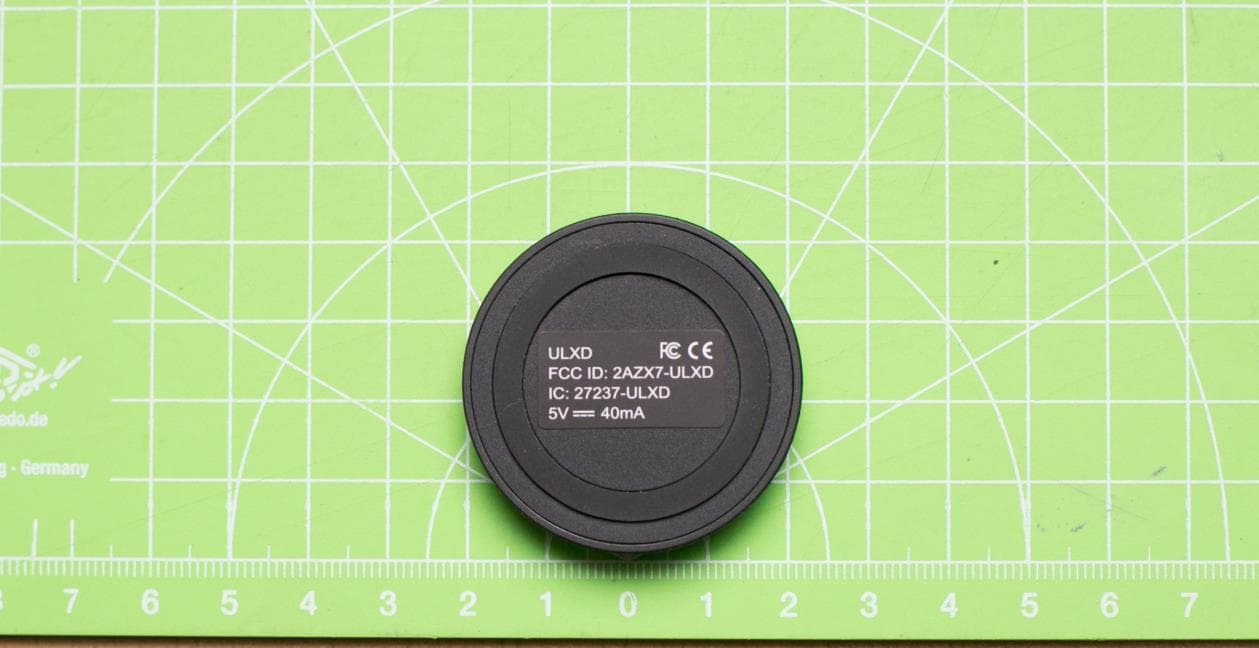
Click to zoom
Application Details
- Equipment Class
- DTS - Digital Transmission System
- Date of Grant
- Oct 30, 2023
- Application Purpose
- Original Equipment
- Date of Application
- Oct 30, 2023
- Equipment Note
- USB Receiver Dongle for Wireless Gaming Mouse
- Frequency Range
- 2402.00000000 - 2480.00000000
- Company
- Finalmouse LLC
- Country
- United States
Documents & Files
Document Text
Text extracted from the exhibit documents filed with the FCC. Open a document above to read the original.
Users Manual
Finalmouse UltralightX ULX Cheetah | Lion | Tiger Package Contents 1.Mouse 2.Dongle 3.USB Charging and Data Cable [1] [2] [3] Mouse Features 1. Left Click 5 Browser Back 4 Browser Forward 3 Middle Click / Scroll Wheel 2 Right Click Mouse Setup ON: Down | OFF: UP | Charging / Data Port (USB C) Get Started 1.Plug charging / data cable into PC 2.Plug dongle into charging / data cable 3.Turn on mouse 4.Other features can be found in Xpanel at finalmouse.com a)DPI b)Polling c)Lift off Distance (LOD) d)Updates e)And more [1] [2] ON: Down | OFF: UP | Usage For optimal wireless performance, use mouse within 12-24in (30-61cm) of dongle and greater than 6ft (1.8m) from sources of 2.4GHz (such as wi-fi routers) ~12-24in ~(30-61cm) Dongle Power Indication •Red periodically – Low power. Charge mouse. •Orange – Charging •Green – Fully Charged When in wired mode the mouse will either be flashing orange to indicate charging or green to indicate fully charged. Safety To achieve maximum safety while using the ULX, we suggest you adopt the following: If you have issues operating the device and troubleshooting does not work unplug the mouse, turn off the mouse and contact Finalmouse at [email protected]. Do not attempt to service or fix the mouse yourself at anytime. Do not take the mouse apart and do not attempt to operate it under abnormal current loads. Changes or modifications not expressly approved by Finalmouse LLC could void the user’s authority to operate the equipment. Replacing a battery with an incorrect type may remove protection, disposing of a battery in a fire or hot oven, or mechanically crushing or cutting a battery, may cause an explosion; keeping a battery in a high-temperature environment may cause an explosion, or leakage of flammable liquid or gas. A battery subjected to extremely low air pressure may cause an explosion or leakage of flammable liquid or gas. Keep the mouse away from liquid, humidity or moisture. Operate the mouse only within the temperature range of 0°C (32°F) to 40°C (104°F). If the temperature exceeds these specified ranges unplug the mouse and turn off the mouse to let the mouse and environment stabilize to the desired level. This device complies with part 15 of the FCC Rules. Operation is subject to the following two conditions: (1) This device may not cause harmful interference, and (2) this device must accept any interference received, including interference that may cause undesired operation This device complies with Industry Canada license-exempt RSS standard(s). Operation is subject to the following two conditions: (1) this device may not cause interference, and (2) this device must accept any interference, including interference that may cause undesired operation of the device. This device operates on the 2.4 GHz band and has a maximum output power of 0.3mW (mouse [Europe/RED only]) and 5.75mW(dongle [Europe/RED only]). The radio equipment meets the essential requirements of Radio Equipment Directive 2014/53/EU. Not intended for children. FCC Note Note: This equipment has been tested and found to comply with the limits for a Class B digital device, pursuant to part 15 of the FCC Rules. These limits are designed to provide reasonable protection against harmful interference in a residential installation. This equipment generates, uses and can radiate radio frequency energy and, if not installed and used in accordance with the instructions, may cause harmful interference to radio communications. However, there is no guarantee that interference will not occur in a particular installation. If this equipment does cause harmful interference to radio or television reception, which can be determined by turning the equipment off and on, the user is encouraged to try to correct the interference by one or more of the following measures: •Reorient or relocate the receiving antenna. •Increase the separation between the equipment and receiver. •Connect the equipment into an outlet on a circuit different from that to which the receiver is connected. •Consult the dealer or an experienced radio/TV technician for help Limitation of Liability Finalmouse shall in no event be liable for any lost profits, loss of information or data, special, incidental, indirect, punitive or consequential or incidental damages, arising in any way out of distribution of, sale of, resale of, use of, or inability to use the Mouse. In no event shall Finalmouse’s liability exceed the retail purchase price of the Mouse. General These terms shall be governed by and construed under the laws of the jurisdiction in which the Mouse was purchased. If any term herein is held to be invalid or unenforceable, then such term (in so far as it is invalid or unenforceable) shall be given no effect and deemed to be excluded without invalidating any of the remaining terms. Finalmouse reserves the right to amend any term at any time without notice. Finalmouse LLC. 802 Indiana Ave, Venice, CA, 90291 Electromagnetic radiation from this device is below the limits specified by the Federal Communications Commission This device has met EU health, safety, and environmental requirements This device should be recycled
Attestation Statements
Rev1/26/2023 FederalCommunicationsCommission AuthorizationandEvaluationDivision 7435OaklandMillsRoad Columbia,MD21046 USA Date:06-12-2023 Ref:AttestationStatementsPart2.911(d)(7)Filing FCCIDorGranteeCode:2AZX7 FinalmouseLLC(“theapplicant”)certifiesthat,asofthedateofthefilingoftheapplication, wedesignateourselvesastheU.S.agentforserviceofprocess. DesignatedU.S.AgentInformation: FRN:0030764948 Name:FinalmouseLLC Address:802Indiana,Venice,CA,90291 ContactPerson:ChadBuchanan Tel.:6144990510 Email:[email protected] Sincerely, FinalmouseLLC ChadBuchanan
Attestation Statements
Rev1/26/2023 FederalCommunicationsCommission AuthorizationandEvaluationDivision 7435OaklandMillsRoad Columbia,MD21046 USA Date:08-16-2023 Ref:AttestationStatementsPart2.911(d)(5)(ii)Filing FCCID:2AZX7-ULXD FINALMOUSELLC(“theapplicant”)certifiesthat,asofthedateofthefilingoftheapplication, theapplicant,isnotidentifiedontheCoveredListasanentityproducing“covered” equipment,nororoneofitssubsidiariesoraffiliates. FinalmouseLLC 802IndianaAve Venice,CA,90291 Phone(614)499-0510 [email protected] Sincerely, ChadBuchanan
Attestation Statements
Rev1/26/2023 FederalCommunicationsCommission AuthorizationandEvaluationDivision 7435OaklandMillsRoad Columbia,MD21046 USA Date:08-16-2023 Ref:AttestationStatementsPart2.911(d)(5)(i)Filing FCCID:2AZX7-ULXD FINALMOUSELLC(“theapplicant”)certifiesthattheequipmentforwhichauthorizationis soughtisnot“covered”equipmentprohibitedfromreceivinganequipmentauthorization pursuanttosection2.903oftheFCCrules. FinalmouseLLC 802IndianaAve Venice,CA,90291 Phone(614)499-0510 [email protected] Sincerely, ChadBuchanan
Cover Letter(s)
PermanentConfidentialityLetter FederalCommunicationsCommission AuthorizationandEvaluationDivision Venice,CA,USA,08-16-2023 Subject:ConfidentialityRequestregardingapplicationforcertificationofFCC ID:2AZX7-ULXD Applicant:FINALMOUSELLC Product:UltralightXgamingmouseUSBdongle. Model:ULXD ToWhomItMayConcern: PursuanttoSections0.457and0.459oftheCommission’sRules,weherebyrequest confidentialtreatmentofinformationaccompanyingthisapplicationasoutlinedbelow: ExhibitTypeFileName BlockDiagram Schematics OperationalDescription UltralightXdongle-BlkDia UltralightXdongle-Schem UltralightXdongle-Opdes Theabovematerialscontaintradesecretsandproprietaryinformationnot customarilyreleasedtothepublic.Thepublicdisclosureofthesematerialsmaybe harmfultotheapplicantandprovideunjustifiedbenefitstoitscompetitors. TheapplicantunderstandsthatpursuanttoSection0.457oftheRules,disclosureof thisapplicationandallaccompanyingdocumentationwillnotbemadebeforethe dateoftheGrantforthisapplication. Ifyouhaveanyqueries,pleasedonothesitatetocontactus. Regards, ChadBuchanan,2023-08-16
Cover Letter(s)
June 12, 2023 Federal Communications Commission 7435 Oakland Mills Road Columbia, MD 21046 FCC Application for FCC ID: 2AZX7-ULXD an original certification. In accordance with: FCC 15.247 The following application is for the UltralightX gaming mouse USB dongle. The radio is an omnidirectional inverted-F monopole etched onto the main PCB. The UltralightX gaming mouse USB dongle utilizes a 2.4 GHz transceiver radio operating over the frequency range of 2402 MHz to 2480 MHz with FSK modulation. Please address any correspondence regarding this filing to my attention at the following address: Chad Buchanan Finalmouse LLC 802 Indiana Ave Venice, CA, 90291 Phone (614) 499-0510 [email protected] Sincerely, Chad Buchanan
Cover Letter(s)
Attn:TIMCOEngineeringInc. 13146NW86thDriveSuite400, Alachua, FL32615 AuthoritytoActasAgent Onourbehalf,IappointM.BrunoPellerinfromEmitechMontigny–30Avenuedes3 Peuples–78180MontignyLeBretonneux,toactasouragentinthepreparationof thisapplicationforequipmentcertification.Icertifythatsubmitteddocumentsproperly describethedeviceorsystemforwhichequipmentcertificationissought.Ialso certifythateachunitmanufactured,importedormarketed,asdefinedintheFederal CommunicationsCommission’sregulationswillhaveaffixedtoitalabelidenticalto thatsubmittedforapprovalwiththisapplication. Forinstanceswhereourauthorizedagentsignstheapplicationforcertificationonour behalf,Iacknowledgethatallresponsibilityforcomplyingwiththetermsand conditionsforcertification,asspecifiedbyTIMCOEngineeringInc.,stillresideswith FinalmouseLLC,802IndianaAve,Venice,CA,90291. ThisauthorizationisvaliduntilfurtherwrittennoticefromFinalmouseLLC. June12,2023 ByChadBuchanan
ID Label/Location Info
FCC Label and Location ULXD
Test Report
v [0.1] — [05/20/2023] TECHNICAL REPORT: Finalmouse Mouse Antenna Report Prepared for: [Finalmouse] Prepared by: [Timothy Milam] Revision History REV Date Author Notes [0.1] [2023-05-20] [Timothy Milam] Antenna Report including tuning details and measurement data. [0.2] [2023-05-20] [Timothy Milam] Added data for changing the 3.0 nH shunt inductor on the Mouse to a 3.9 and retesting Finalmouse USB Dongle and Wireless Mouse Antenna Evaluation Report Finalmouse requested SMT tuning of the antennas in two products, 1) a USB dongle and 2) a wireless mouse. Due to FCC testing that will occur in a few days, there was no option offered for changing the antenna or any other layout. Later it was agreed to trim the Dongle antenna to see if it would tune better by the method. It did and radiated performance was better also. This trimmed version can be used during the FCC testing, since no copper tape was used, but the antenna radiator length will have to be the same for the final production board. 1 Test Equipment Used During this Antenna Feasibility Study Vector Network Analyzer “VNA” used was a CMT (Copper Mountain Technologies) Model #: S5085; a 50 Ohm, 2-Port, 2-Path, 9 kHz to 8.5 GHz, VNA S/N: 20107496. A CIA custom designed and built, 13 ft. x 9 ft. x 9 ft. anechoic antenna measurement chamber fully lined with Cumming Microwave “C-RAM SFC-18”, 18 in. deep pyramidal absorber and associated Cumming Microwave corner treatments and walkway absorber, see image below. Chamber source antenna is a RF Spin Model “QRH11”, Quad Ridged Horn Antenna, S/N: 200721Q11. Various Mini-Circuits “Flex Test” test cables and Precision Pasternack connectors and adapters were used in the closed system setup, as well as Teledyne “CCR33S80T” SPDT coaxial switches. CMT “TW-SMA” Torque Wrench (no S/N). CMT “S911T” Calibration Kit, SN: A266049. Omano 7x to 45 x trinocular microscope with Hayear Model: HY-5099 (no S/N) Industrial Inspection Camera and SW. CIA’s Anechoic Chamber 2 DUTs as Used for the VSWR and Radiated Pattern Measurements The Dongle and Mouse DUTs were supplied by Finalmouse and contained the latest hardware as it intended for FCC testing and ultimately production. Images of both units are shown below. Fully assembled Dongle as tested Fully assembled Mouse as tested 3 Measurement Data The antenna parameters measured were the VSWR and 6 principal radiation patterns (vertical and horizontal polarized data for each of the 3 principal planes of radiation). VSWR for the Dongle was measured on a wooden surface, the Mouse was also measured on a wooden surface, but had a mouse pad under it. Comparison VSWR was also supplied for the mouse with a hand on it as if it were being used normally (memory trace) and just sitting on the mouse pad with no human interaction; no discernable difference was seen. 3.1 Radiated Pattern Description Radiated Pattern Illustration Sphere NOTE: To minimize the number of illustrations a generic DUT is shown inside the pattern illustration sphere. NOTE: The source antenna is represented as pointing toward the DUT from the 0-degree data point as shown in the plots below. NOTE: Some labs have different interpretations of the spherical as well as the Cartesian coordinate systems than given below. They may point x, y, and z in different directions or define + or – signs differently on both coordinate systems. The descriptions below use the conventions that are used in the CIA lab. 3.1.1 Three Principal Planes of Radiation The red horizontal line, circumnavigating the sphere, represents the azimuth plane of radiation (cut), as labeled in the plots below. o Azimuth is also known as just the Phi plane or Phi at Theta = 90 o in a spherical coordinate system or the xy plane in the Cartesian coordinate system. The dark green vertical line represents the Elevation Front to Back (F/B) cut. o AKA the Theta plane at (that passes through) Phi = 0 o and 180 o in a spherical coordinate system or the yz plane in the Cartesian coordinate system. The dark blue vertical line represents the Elevation Left to Right (L/R) cut. o AKA the Theta cut at Phi = 90 o and 270 o or the xz plane in the Cartesian coordinate system. FYI: Some labs use Phi = +90 o and -90 o in a spherical coordinate system. When radiation pattern data is measured in both polarizations (V and H), the 6 resulting patterns are known as the 6 principal planes or “cuts”. The planes represented by the white lines are only measured when a full 3D data set is required. All principal and secondary planes or cuts are measured by positioning the DUT appropriately, for the plane to be measured and rotating the pedestal by 360 degrees, capturing VNA S21 (received signal amplitude) measurement data every 10 o . 4.1 Dongle Matched by only Trimming the PIFA Radiator Inside view with the 1.37 mm U.FL test cable attachment to the Dongle’s PCB CPW transmission line and trimmed PIFA 4.1.1 VSWR VSWR for the Dongle, with a 0 Ohm jumper in the L5 series position of the antenna matching circuit and the PIFA radiator trimmed by 3.85 mm. The Dongle tuned much better by the trimming method. 4 Finalmouse Antenna Data 4.1.2 Schematic with 0 Ohm Jumper Location Schematic markup for the Dongle antenna matching components. The red markup value (0 Ohm jumper) and a 3.85 mm shorter PIA radiator tuned the antenna as shown in the VSWR plot above. 4.1.3 PCBA After Trimming the Antenna Dongle PIFA radiator trimmed 3.85 mm. No SMT tuning was required. [redacted] 4.1.4 Radiated Patterns 4.2 Mouse with 3.9 nH Shunt Inductor No change to the DUT images. 4.2.1 VSWR VSWR of the mouse PIFA with a series 1.0 pF cap (muRata P/N: GJM1555C1H1R0BB01) in position R33 and a shunt 3.9 nH (TDK P/N: MLG1005S3N9CT000) inductor in position C15 Schematic markup for the Mouse antenna matching components. Red values were used to tune the antenna at the length supplied, per Finalmouse request on 05/20/2023. [ redacted ] 4.2.2 Radiated Patterns; The plot scale has been kept to match the previous Mouse…
Text truncated - open the document above for the full version.
Test Report
RRA-EMIESS23C288FIN-02A v1 Page 37 out of 76 RRA-EMIESS23C288FIN-02A v1 Page 38 out of 76 6.4. Additional provisions to the general radiated emissions limitation Reference standard: FCC 47 CFR PART 15 : 2022 RSS-247 Issue 2 : 2017 Test method: § 15.215 (c) and § 15.247 d) of FCC 47 CFR PART 15 : 2022 § 5.5 of RSS-247 Issue 2 : 2017 General test setup: E.U.T. is set on an insulating support at 80 cm above the ground reference plane. Measurement are done on a normalized test site. The test antenna is oriented in the two polarizations (vertical and horizontal), and the product is rotated at 360° in the horizontal plane (See photo(s) for initial position of the EUT(0°)). If applicable the test antenna was raised and lowered through the specified range of height until a maximum signal level is detected. For portable equipements a research of maximum level is done on the 3 axes. Only the highest levels are recorded. LABORATORY PARAMETERS: REQUIRED PRIOR TO THE TEST DURING THE TEST Ambient Temperature 10 to 40 °C 23.5°C Relative Humidity 10 to 90 % 44.5% Atmospheric pressure N/A 1019 hPa Test method deviation: No Supplementary information: - TEST EQUIPMENT USED ROW_T O_D ELET E Order Nr Category Manufacturer Type Last validity date Next validity date 0941 Antenna Emco 3115 01/03/2022 01/05/2025 17270 Cable Huber + Suhner N-6m 10/06/2022 10/08/2024 14228 Cable C&C N-4m 10/06/2022 10/08/2024 17272 Cable Huber + Suhner N-10m 01/07/2022 01/09/2024 14768 Receiver Rohde & Schwarz ESR7 02/01/2023 02/03/2024 14803 Shielded enclosure Comtest SAC 3m Blank cells = Permanent validity RRA-EMIESS23C288FIN-02A v1 Page 39 out of 76 Band Edge measurement : For UltralightX Medium Polarization of test antenna: Vertical (height = 150 cm) For 2402 MHz Position of equipment: azimuth = 305° Polarization of test antenna: Vertical (height = 170 cm) For 2480 MHz Position of equipment: azimuth = 305° For UltralightX Dongle Polarization of test antenna: Vertical (height = 125 cm) For 2402 MHz Position of equipment: azimuth = 260° Polarization of test antenna: Vertical (height = 155 cm) For 2480 MHz Position of equipment: azimuth = 260° E.U.T. Frequency (MHz) Field Strength Level of fundamental (dBμV/m) Detector (Peak or Average) Frequency of maximum Band-edges Emission (MHz) Calculated Max Out of Band Emission Level (dBμV/m) Limit (dBV/m) Margin (dB) UltralightX Medium 2401.96 89.7 Average 2338.9 41.5 54 12.5 2480.08 91.3 Average 2488.2 41.9 54 12.1 UltralightX Dongle 2401.96 102.4 Average 2338.0 41.1 54 12.9 2480.02 102.3 Average 2484.4 42.1 54 11.9 RRA-EMIESS23C288FIN-02A v1 Page 40 out of 76 For UltralightX Medium RRA-EMIESS23C288FIN-02A v1 Page 41 out of 76 For UltralightX Dongle RRA-EMIESS23C288FIN-02A v1 Page 42 out of 76 6.5. Unintentional radiated emissions and transmitter unwanted emission in the band 9 kHz – 26 GHz Reference standard: FCC 47 CFR PART 15 : 2022 RSS-Gen Issue 5 : 2019 Test method: § 15.205; § 15.209 and § 15.247 of FCC 47 CFR PART 15 : 2022 § 6.13 of RSS-Gen Issue 5 : 2019 General test setup: E.U.T. is set on an insulating support at 0.8 m (<1GHz) and 1.5 m (>1GHz) above the ground reference plane. For maximum meter reading at each frequency, the antenna height is adjusted between 1 m and 4 m above the ground plane for 9 kHz - 26 GHz. A 360 degrees rotation of the EUT is performed in vertical and horizontal polarization. TESTED CONFIGURATION PARAMETER VERDICT Maxhold 360° - Tx 2402 MHz channel - UltralightX Medium 9kHz-30MHz N/A (1) Maxhold 360° - Tx 2440 MHz channel - UltralightX Medium 9kHz-30MHz N/A (1) Maxhold 360° - Tx 2480 MHz channel - UltralightX Medium 9kHz-30MHz N/A (1) Maxhold 360° - Tx 2402 MHz channel - UltralightX Dongle 9kHz-30MHz N/A (1) Maxhold 360° - Tx 2440 MHz channel - UltralightX Dongle 9kHz-30MHz N/A (1) Maxhold 360° - Tx 2480 MHz channel - UltralightX Dongle 9kHz-30MHz N/A (1) Maxhold 360° - Tx 2402 MHz channel - UltralightX Medium 30MHz-1GHz PASS Maxhold 360° - Tx 2440 MHz channel - UltralightX Medium 30MHz-1GHz PASS Maxhold 360° - Tx 2480 MHz channel - UltralightX Medium 30MHz-1GHz PASS Maxhold 360° - Tx 2402 MHz channel - UltralightX Dongle 30MHz-1GHz PASS Maxhold 360° - Tx 2440 MHz channel - UltralightX Dongle 30MHz-1GHz PASS Maxhold 360° - Tx 2480 MHz channel - UltralightX Dongle 30MHz-1GHz PASS Maxhold 360° - Tx 2402 MHz channel - UltralightX Medium 1GHz-26GHz PASS Maxhold 360° - Tx 2440 MHz channel - UltralightX Medium 1GHz-26GHz PASS Maxhold 360° - Tx 2480 MHz channel - UltralightX Medium 1GHz-26GHz PASS Maxhold 360° - Tx 2402 MHz channel - UltralightX Dongle 1GHz-26GHz PASS Maxhold 360° - Tx 2440 MHz channel - UltralightX Dongle 1GHz-26GHz PASS Maxhold 360° - Tx 2480 MHz channel - UltralightX Dongle 1GHz-26GHz PASS LABORATORY PARAMETERS: REQUIRED PRIOR TO THE TEST DURING THE TEST Ambient Temperature 10 to 40 °C 22.4°C Relative Humidity 10 to 90 % 48% Atmospheric pressure N/A 1025 hPa Test method deviation: No Supplementary information: (1) : No EUT internal frequencies on this frequency band. RRA-EMIESS23C288FIN-02A v1 Page 43 out of 76 TEST EQUIPMENT USED ROW_T O_D ELET E CATEGORY BRAND TYPE IDENTIFIER CAL. DATE CAL. DUE Amplifier Mini-circuit ZFL-1000LN 0364 15/02/2023 15/04/2024 Amplifier Agilent 8449B 14487 16/02/2023 16/04/2024 Antenna Schwarzbeck VHA 9103 3426 21/04/2023 21/06/2025 Antenna Schwarzbeck UHALP 9108A 3106 25/04/2023 25/06/2025 Antenna Emco 3115 0941 01/03/2022 01/05/2025 Antenna Oritel CM 42/25 1045 01/03/2022 01/05/2025 Cable Sucoflex N-3m 12929 04/07/2023 04/09/2024 Cable C&C N-12m 11173 09/09/2022 09/11/2024 Cable Huber + Suhner N-6m 17271 20/06/2022 20/08/2024 Cable C&C K-2m 11132 23/09/2022 23/11/2024 Cable C&C K-4m 11134 23/09/2022 23/11/2024 Filter Micro-Tronics HPM 14758 4691 13/06/2022 13/08/2025 Shielded enclosure Comtest SAC 3m 14803 Software Nexio BAT EMC 0000 Spectrum analyzer Rohde & Schwarz ESR7 12811 22/05/2023 22/07/2024 Spectrum analyzer Rohde & Schwarz FSP40 (V 4.00SP1- V3.0-10-2) 5175 16/03/2023 16/05/2025 BAT-EMC software ve…
Text truncated - open the document above for the full version.
Test Report
Siège Social : Emitech - 3, avenue des Coudriers - Z.A. de l’Observatoire - 78180 MONTIGNY LE BX - France Siret : 344 545 645 00022 - Tél. : 33 (0)1 30 57 55 55 - Fax : 33 (0)1 30 43 74 48 - E-mail : [email protected] - URL : www.emitech.fr SAS au capital de 1 560 000 € - R.C.S. VERSAILLES 344 545 645 - APE 7112B RRA-EMIESS23C288FIN-02A v1 Certain services reported in this document are not covered by the accreditation. They are identified by the symbol (*) Duplication of this test report is only permitted for an integral photographic facsimile. It includes the number of pages referenced here above. This document is the result of testing a specimen or a sample of the product submitted. It does not imply an assessment of the conformity of the whole manufactured products of the tested sample. LISTE DES SITES ACCREDITES ET PORTEES DISPONIBLES SUR WWW.COFRAC.FR ACCREDITATIONS N° 1-0826, 1-0827, 1-1925, 1-2069,1-2070, 1-2206, 1-2376 & 1-6086 LISTE DES SITES ACCREDITES ET PORTEES DISPONIBLES SUR WWW.COFRAC.FR ACCREDITATIONS N° 1-0826, 1-0827, 1-1925, 1-2069,1-2070, 1-2206, 1-2376 & 1-6086 LIST OF ACCREDITED SITES AND SCOPE AVALAIBLE ON WWW.COFRAC.FR TESTING ACCREDITATIONS N° 1-0826, 1-0827, 1-1925, 1-2069,1-2070, 1-2206, 1-2376 & 1-6086 This report cancels and replaces the test report N° RRA-EMIESS23C288FIN-01A v0 Test report issued under the responsibility of: EMITECH ILE DE FRANCE Laboratory MRA US-EU Designation Number: FR0004 IC Assigned Code: 4379A RADIO TEST REPORT FCC 47 CFR PART 15 : 2022 (§15.247) RSS-247_Issue 2 : 2017 RSS-Gen_Issue 5 : 2019 Company ....................................... : Finalmouse LLC Address. .......................................... : 802 Indiana ave VENICE, CA USA 90291 Test item description. .................. : Wireless Gaming Mouse and Wireless Gaming Mouse USB Dongle Trade Mark. .................................... : Finalmouse Manufacturer................................... : Finalmouse LLC Model/Type reference. .................... : UltralightX Medium : ULXM/ UltralightX Dongle : ULXD Ratings. ........................................... : 5Vdc Testing Laboratory ....................... : EMITECH ILE DE FRANCE Laboratory Address. .......................................... : 30-32, avenue des 3 Peuples 78180 MONTIGNY-LE-BRETONNEUX FRANCE Report Reference No. ................... : RRA-EMIESS23C288FIN-02A v1 Test procedure. .............................. : FCC and CANADA marking Diffusion. ......................................... : Mr VINCENT Applicant’s name. ........................... : Mr VINCENT Date of issue. .................................. : 25/09/2023 Total number of pages. ................... : 76 Revision. ......................................... : V1 Compiled by. ................................... : C.A. ROBERT (Tests technician) Approved by (+ signature). ............. : Quality approval .............................. : RRA-EMIESS23C288FIN-02A v1 Page 2 out of 76 REPORT INDEX: 1. GENERAL INFORMATIONS .......................................................................................................................... 3 2. REFERENCE DOCUMENTS .......................................................................................................................... 4 3. EQUIPMENT TECHNICAL DESCRIPTION .................................................................................................... 5 3.1. TEST CONDITIONS ................................................................................................................................... 5 3.2. E.U.T OVERVIEW .................................................................................................................................... 6 3.3. E.U.T MARKING PLATE ............................................................................................................................ 8 3.4. EUT ELECTRONIC BOARD ........................................................................................................................ 8 3.5. E.U.T MECHANICAL AND ELECTRICAL DESIGN .........................................................................................10 3.6. EUT INPUT/OUTPUT PORTS ....................................................................................................................10 3.7. SUPPORTING EQUIPMENT USED DURING TEST ........................................................................................11 3.8. AUXILIARY EQUIPMENT ...........................................................................................................................11 3.9. E.U.T RADIO SPECIFICATIONS ................................................................................................................12 4. RESULT SUMMARY .....................................................................................................................................13 5. MEASUREMENT UNCERTAINTY ................................................................................................................16 6. TEST CONDITIONS AND RESULTS ...........................................................................................................17 6.1. FREQUENCY HOPPING AND DIGITAL MODULATION SYSTEMS ......................................................................17 6.2. TRANSMITTER OUTPUT POWER ...............................................................................................................27 6.3. PEAK POWER SPECTRAL DENSITY ...........................................................................................................33 6.4. ADDITIONAL PROVISIONS TO THE GENERAL RADIATED EMISSIONS LIMITATION.............................................38 6.5. UNINTENTIONAL RADIATED EMISSIONS AND TRANSMITTER UNWANTED EMISSION IN THE BAND 9 KHZ – 26 GHZ ....................................................................................................... 42 6.6. UNINTENTIONAL RADIATED EMISSIONS IN THE BAND 30 MHZ – 13 GHZ .................…
Text truncated - open the document above for the full version.
Contact Information
Applicant
Chad Buchanan
Test Firm
EMITECH MontignyFabien Verneiges
Technical Specifications
| # | Rule Parts | Frequency Range | Power Output |
|---|---|---|---|
| 1 | 15C | 2.40 GHz - 2.48 GHz | 4.00 mW |