2AZXT-AF2104Crystal (2) Color Bluetooth Earbuds
ShenZhen Houshuxia Technology Co., LTD
Click to zoom
Application Details
- Equipment Class
- DSS - Part 15 Spread Spectrum Transmitter
- Date of Grant
- Dec 13, 2022
- Application Purpose
- Original Equipment
- Date of Application
- Dec 13, 2022
- Equipment Note
- Crystal (2) Color Bluetooth Earbuds
- Frequency Range
- 2402.00000000 - 2480.00000000
- Country
- China
Documents & Files
Document Text
Text extracted from the exhibit documents filed with the FCC. Open a document above to read the original.
Users Manual
Crystal(2) T8 Crystal (2) Color Bluetooth Earbuds Quick Start Guide Explore the future Future of Sound, Listen 封面 温馨提示 Friendly Reminder 注意事項 ※首次使用需先把耳机从充电仓中取出,撕掉耳机上的保护膜,将耳机 重新放入充电仓进行激活。 ※耳机电量不足时请先充电。 For the first use, you need to take the earbud out of the charging case, tear off the insulating sticker on the earbud, put the earbud into the charging case to complete the activation. Please charge the earbud first when the power is low. ※初めて使用する場合は、充電ケースからイヤホンを取り出し、イヤ ホンの絶縁シールをはがし、イヤホンを充電ケースに入れてアクティ ベーションをしてください。 ※使用前にイヤホンの電気量が十分かどうかを確認してください。電 気がない場合はまず充電してください。 参数/包装清单 包装清单 CN 型号 产品名称 蓝牙配对名称 蓝牙版本 音频解码协议 传输范围 扬声器类型 扬声器规格 扬声器灵敏度 频率范围 音乐时间 通话时间 总工作时间 耳机电池 充电盒电池 耳机充电时间 充电盒充电时间 充电盒输入 耳机尺寸 单耳机重量 整体尺寸 总重量 材料 防水等级 T8 小晶彩(2)无线蓝牙耳机 ACEFAST Crystal (2) T8 蓝牙5.3 + EDR SBC/AAC 10m 同轴双动圈 Φ10mm + Φ6mm 106±3dB 20Hz~20kHz 约 7 小时(70% 音量) 约 4 小时(70% 音量) 约30小时 45mAh 480mAh,可为耳机充电4次 约1小时 约1.5小时 5V 0.45A 约36.8x24x15.6mm 约11g 约51x57.4x24mm 约47g PC + 硅胶 IPX4 使用说明 产品出厂时已默认左右耳机配对成功,第一次连接手机时按以下步骤进行操作: 1.取出耳机自动开机,等待约3秒钟后左右耳机会自动互连。 2.打开手机蓝牙,搜索到ACEFAST Crystal (2) T8,点击进行连接。配对成功后您会听到提示音,手机显示已连接。 再次使用时,耳机开机配对后,会自动回连连接过的手机。如连接不到手机,请从手机蓝牙菜单中手动操作和耳机连接。 ACEFAST Crystal (2) T8 ACEFAST Crystal (2) T8 提示: *耳机和设备连接时,为避免左右耳之间回连失败,耳机需要同时从充电仓中取出。 *您有5分钟连接耳机和您的设备,否则耳机将自动关机。将耳机放回充电仓即能重新进入配对模式。 *左右耳均可单独使用。 *如长时间无法配对成功,请参照恢复出厂设置操作步骤对耳机进行复位操作。 *如左右耳连接后一边无声,请参照恢复出厂设置操作步骤对耳机进行复位操作。 充电仓电量<10% 充电仓充电时,暖红色灯呼吸渐变 充电仓充电时,对应产品颜色灯呼吸渐变 充电仓不充电时,取出/放入耳机暖红色灯呼吸渐变三次后熄灭 充电仓不充电时,取出/放入耳机对应产品颜色灯呼吸渐变三次后熄灭 充电仓电量≥10% 操作方式 充电注意事项: 使用输出电压为直流DC5V的充电器、PC电脑的USB口或带USB口 输出的充电器(必须选择正规厂家安全认证过的充电器); 温馨提示: 本产品含内置可充电电池,电池使用安全警示: 禁止撞击,挤压或投入火中;若出现严重鼓胀,请勿继续使用。 请勿置于高温环境中;电池浸水后禁止使用。 请勿尝试从耳机中取出电池,以免毁坏耳机。 耳机在搁置时会自动耗电,建议每1个月给耳机充一次电。 CN 充电: 1) 耳机充电:当低电量时,耳机会发出语音提醒。请将耳机放入充电盒内开始充电。 2) 充电盒充电:当充电仓低电量时,请使用USB-C充电线,接入充电盒接口开始充电。 呼吸灯灯效: 充电盒数码屏及灯效显示: 1)LR和四个电量格表示左右耳机电量,当放入或取出耳机时,充电仓数码屏闪烁,呼吸灯渐变三次后灯灭。 2) 对充电仓进行充电时,充电仓数码屏亮起,电量末位会闪烁,电量充满时,显示OK。 I:0~25% II:26%~50% III:51%~75% IIII:76%~100% 操作方式 CN 功能操作: 1)播放音乐:双击触控区或者在手机上操作播放器(某些手机在连接上蓝牙立体声時会自动启动音乐播放器)。 2)暂停音乐:播放音乐时双击触控区或者在手机上操作播放器。 3)下一曲:在播放音乐时,三击右耳触控区。 4)上一曲:在播放音乐时,三击左耳触控区。 5)音量+:单击右耳触控区,最大音量时会有提示音。 6)音量-:单击左耳触控区,最小音量时会有提示音。 7)唤醒语音助手:长触左耳触控区2s,听到提示音后松手进入/退出语音助手。 8)进入/退出游戏模式:双耳使用时,长触右耳触控区2s,听到提示音后进入/退出游戏模式。 双击触控区 三击右耳触控区 三击左耳触控区 单击右耳触控区 单击左耳触控区 恢复出厂设置:同时长触左右耳触控区5S,白灯闪烁,复位操作成功。 *由于蓝牙耳机特性,区域中的电磁波干扰可能会造成连接中断或卡顿。基于无线技术特性,当设备同时进行显示功能和发射蓝牙声音 信号时,在音频信号和视频信号中可能会产生“延时”,即声音与画面不同步。 接/打电话: 1)接听电话:来电时,双击触控区。 2)结束通话:通话中,双击触控区。 操作方式 88888888888 88888888888 88888888888 3)拒接电话:来电时,长触触控区2秒。 88888888888 来电时,双击触控区。 长触触控区2秒 开\关机: 1)开机:①取出耳机,耳机自动开机;②关机状态下,单触触控区。开机后耳机进入蓝牙配对状态,led灯开始闪烁。 2)关机:耳机放入充电盒内耳机自动关机。 充电触点 麦克风 呼吸灯 产品信息 CN 充电盒 LED数显 USB-C 充电口 触控区 感谢您购买本产品。 请仔细阅读本用户手册并妥善保管以备日后参考。 如果您需要任何帮助,请联系我们的支持团队。 耳机指示灯 硅胶套 x 1 USB-C 充电线 x 1 硅胶挂绳 x 1 SS/S/M/L 耳帽 ×4 对 充电仓 x 1 耳帽收纳盒 x 1 耳机 x 2 SSS ML 说明书 x 1 CNCN ACEFAST Crystal (2) T8 ACEFAST Crystal (2) T8 Breathing light effect: Silicone case × 1 USB-C cable × 1 Silicone lanyard × 1 SS/S/M/L eartips × 4 pairs Charging case × 1 Eartips storage box × 1 Earbuds × 2 SSS ML Manual × 1 Charging case power level 10% When the charging case is charging, the warm red gradient light breathes. When the charging case is charging, the product corresponding color light will breath. When the charging case is not charging, take out/put in the earbuds - the warm red light turns off after breathing three times. When the charging case is not charging, take out/put in the earbud, product corresponding color light turns off after breathing three times. Charging case power level ≥10% Charge: 1) Charging the earbud: when the battery is low, the earbud will issue a voice reminder. Please put the earbud in the charging case to start charging. 2) Charging in the charging case: when the battery of the charging case is low, please use the USB-C charging cable and connect it to the charging case interface to start charging. Charging case display and lighting effect: 1) The LR and four power cells indicate the power of the left and right earbuds. When the earbuds are placed in or removed from case, the digital display of the charging case flashes, and the breathing light turns off after three flashes. 2) When charging the charging case, the digital display of the charging case lights up, the last cell of the battery will flash, and when the battery is fully charged, it will display OK. I0~25% II26%~50% III51%~75% IIII76%~100% Operation method: 1) Play music: double-tap the touch area or operate the player on the phone. (some mobile phones will automatically start the music player when connected to a Bluetooth stereo). 2) Pause the music: double-tap the touch area when playing music or operate the player on the phone. 3) Next song: when playing music, three taps on the touch area of the right earbud. 4) Previous song: when playing music, three taps on the touch area of the left earbud. 5) Volume +: tap the touch area of the right earbud, and there will be a tone at the maximum volume. 6) Volume-: tap the touch area of the left earbud, and there will be a tone at the minimum volume. 7) Wake up the voice assistant: touch the touch area of the left earbud for a 2s, and let go after hearing the tone to enter/exit the voice assistant. 8) Enter/exit game mode: when using both earbuds, touch the touch area of the right earbud for 2s, enter/exit game mode accompanied by the tone. Double-tap the touch area Three taps on the touch area of the right earbud Three taps on the touch area of the left earbud Tap the touch area of the right earbud Tap the touch area of the left earbud Restore factory settings: long touch the left and right earbud touch areas for 5s at the same time, the white light flashes, the reset operation is successful. *Due to the characteristics of Bluetooth earbuds, electromagnetic wave interference in the area may cause connection interruptions or freezes. Based on the characteristics of wireless technology, when the device performs the display function and transmits the Bluetooth sound signal at the same time, there may be a "delay" in the a…
Text truncated - open the document above for the full version.
Attestation Statements
ShenZhen Houshuxia Technology Co., LTD Model Difference Product description: Crystal (2) Color Bluetooth Earbuds Model name: T8 AT8 Trade Name: s FCC ID: 2AZXT-AF2104 All the model are the same circuit and RF module, except model names. Regards Sincerely Client’s signature: Client’s name / title : Xin Xie/Manager Contact information / address: Rm203, 2nd Floor, Building C,Youth Pioneer Park, Jianshe East Road, TSinghua Community, Longhua Street, Longhua District, Shenzhen, P. R. China
Cover Letter(s)
ShenZhen Houshuxia Technology Co., LTD 2022.12.09 Eurofins Electrical and Electronic Testing NA, Inc. 914 W. Patapsco Avenue Baltimore, MD 21230 USA RE: CONFIDENTIALITY REQUEST FOR EUT NAME: Crystal (2) Color Bluetooth Earbuds Trademark: MODEL : T8 AT8 FCC ID: 2AZXT-AF2104 To Whom It May Concern: This letter serves as an official request for confidentiality under sections 0.457 and 0.459 of CFR 47. We have requested that the - Block Diagram - Schematics - Operational Description required to be submitted with this application be permanently withheld from public review. The above materials contain trade secrets and proprietary information not customarily released to the public. The public disclosure of these materials may be harmful to the applicant and provide unjustified benefits to its competitors. Please contact me if there is any information you may need. Sincerely, Client’s signature: Client’s name / title : Xin Xie/Manager Contact information / address: Rm203, 2nd Floor, Building C,Youth Pioneer Park, Jianshe East Road, TSinghua Community, Longhua Street, Longhua District, Shenzhen, P. R. China
External Photos
External Photos
ID Label/Location Info
Label & label location 10*5mm FCC ID: 2AZXT-AF2104
Internal Photos
Internal Photos Antenna
RF Exposure Info
RF EXPOSURE EVALUATION METHOD FCC ID: 2AZXT-AF2104 Applicable standard: In accordance with FCC 47 CFR part 2 (2.1093) this device has been defined as a portable device which is defined as a transmitting device designed to be used so that the radiating structure(s) of the device is/are within 20 centimeters of the body of the user. Portable devices must be evaluated using the specified in FCC 47 CFR part 2 (2.1093) and ANSI/IEEEC95.1-1992. and had been tested in accordance with the measurement methods and procedures specified in IEEE 1528-2003. Per FCC KDB 447498 D01 v06, the 1-g and 10-g SAR test exclusion thresholds for 100 MHz to 6 GHz at test separation distances s 50 mm are determined by: SAR Test Exclusion Thresholds for 100 MHz – 6 GHz and ≤ 50 mm Approximate SAR Test Exclusion Power Thresholds at Selected Frequencies and Test Separation Distances are illustrated in the following Table. The 1-g and 10-g SAR test exclusion thresholds for 100 MHz to 6 GHz at test separation distances ≤ 50 mm are determined by: [(max. power of channel, including tune-up tolerance, mW)/(min. test separation distance, mm)] · [√f(GHz)] ≤ 3.0 for 1-g SAR and ≤ 7.5 for 10-g extremity SAR,where f(GHz) is the RF channel transmit frequency in GHz Power and distance are rounded to the nearest mW and mm before calculation The result is rounded to one decimal place for comparison The test exclusions are applicable only when the minimum test separation distance is ≤ 50 mm and for transmission frequencies between 100 MHz and 6 GHz. When the minimum test separation distance is < 5 mm, a distance of 5 mm is applied to determine SAR test exclusion. BT GFSK Low 1.76 21 GFSK Middle 2.2 21 GFSK High 2.61 21 π/4DQPSK Low 1.74 21 π/4DQPSK Middle 2.24 21 π/4DQPSK High 2.67 21 8DPSK Low 1.72 21 8DPSK Middle 2.24 21 8DPSK High 2.63 21 max possible output power (PK,conducted):3±1dBm 0.54dBi logarithmic terms convert to numeric result is nearly 1.132 4dBm=2.51mW 2402MHz [(max. power of channel, including tune-up tolerance, mW)/(min. test separation distance,mm)] · [√f(GHz)]= 2.51/5*√2.402=0.78≤3.0 2441MHz [(max. power of channel, including tune-up tolerance, mW)/(min. test separation distance,mm)] · [√f(GHz)]= 2.51/5*√2.440=0.78≤3.0 2480MHz [(max. power of channel, including tune-up tolerance, mW)/(min. test separation distance,mm)] · [√f(GHz)]= 2.51/5*√2.48=0.79≤3.0 Conclusion: 1. [(max. power of channel, including tune-up tolerance, mW)/(min. test separation distance, mm)] * [√f(GHz)] < 3.0. 2. SAR Test Exclusion Thresholds is 3.0 for separation distance 5mm. Therefore, SAR test is not required.
Test Report
Page 1 of 9 Huizhou Speed Wireless Technology Co., Ltd Tel:13033544943 Fax:13033544943 No.138, Shangxia Section, Hi-tech District East-river, Huizhou, Guangdong, China,Post code 516600 Customer EVOIOT Item No. IT93F Right/Left antenna code IT93F-ANT Version T05 Date 2022.12.05 Made by RF checked by PE checked by Approved by speed Yingying.Tian Vera Xiangxiang.sun Customer Confirmation: Page 2 of 9 Project basic information Antenna Type Monopole Antenna Material LDS Frequency Band BT OperatingFrequency(MHz) 2400-2500 1、 Project Information 1.1Appearance and Dimensions 1.2 Antenna sample picture 2、Antenna test equipment List of meters:Agilent 5071B; 2.1The principle diagram of the ETS anochoic chamber Page 3 of 9 样机 网络分析仪 同轴电缆 支撑架 Picture1.Antenna static test connection method 2.2 Pictures of the ETS anochoic chamber Inside the ETS anochoic chamber Test Machine 3、Electrical Characteristics 3.1 Test Environment Conditions Page 4 of 9 3.2 VSWR(IT93F-ant)-left 3.3 VSWR(IT93F-ant)-right 3.4 Smith Chart(IT93F-ant)-left Page 5 of 9 3.5 Smith Chart(IT93F-ant)-right 3.6 The antenna matching circuit Number L1202 R1203 L1212 Value NC 0.5pf NC Page 6 of 9 3.7 Antenna gain( IT93F-ant)-left frequency(MHz) gain (dBi) efficiency (%) 2400 -0.46 40.7464 2410 -0.42 41.3556 2420 -0.22 42.051 2430 -0.13 42.5519 2440 0.16 44.0773 2450 0.37 45.0317 2460 0.48 45.7971 2470 0.54 46.1244 2480 0.41 44.6683 2490 0.17 42.9741 2500 0.20 40.6187 Page 7 of 9 Total Resp o n se (d B) -12 0 -10 -8 -6 -4 -2 X Y Z Azi m uth = 0.0 El evati on = 0.0 Rol l = 0.0 3.8 Antenna gain IT93F-ant)-right frequency(MHz) gain (dBi) efficiency 2400 0.04 47.5161 2410 0.04 46.3017 2420 0.08 46.9533 2430 0.12 47.6635 2440 0.28 48.628 Cut1 Po wer (d Bm ) Angl e (? Scal e: 2/di v Mi n: -18 Max : 0 0 180 30 210 60 240 90270 120 300 150 330 2440 MHz Cut2 Po wer (d Bm ) Angl e (? Scal e: 5/di v Mi n: -25 Max : 0 0 180 30 210 60 240 90270 120 300 150 330 2440 MHz Cut3 Po wer (d Bm ) Angl e (? Scal e: 5/di v Mi n: -25 Max : 0 0 180 30 210 60 240 90270 120 300 150 330 2440 MHz Page 8 of 9 2450 0.37 50.8559 2460 0.49 51.8961 2470 0.54 51.4704 2480 0.48 51.111 2490 0.40 49.046 2500 0.19 48.4062 Total Resp o n se (d B) -12 0 -10 -8 -6 -4 -2 X Y Z Azi m uth = 0.0 El evati on = 0.0 Rol l = 0.0 Cut1 Po wer (d Bm ) Angl e (? Scal e: 2/di v Mi n: -14 Max : 2 0 180 30 210 60 240 90270 120 300 150 330 2440 MHz Cut2 Po wer (d Bm ) Angl e (? Scal e: 2/di v Mi n: -20 Max : 0 0 180 30 210 60 240 90270 120 300 150 330 2440 MHz Cut3 Po wer (d Bm ) Angl e (? Scal e: 5/di v Mi n: -25 Max : 0 0 180 30 210 60 240 90270 120 300 150 330 2440 MHz Page 9 of 9 4、Test conclusion The index meets the BT normal antenna index Note: This antenna is only suitable for debugging prototypes. Any motherboard version changes or RF material changes must be tested and verified by our company before it can be used.
Test Report
No.:BCTC/RF-EMC-005 Page 1 of 82 Edition:A.5 TEST REPORT Shenzhen BCTC Testing Co., Ltd. Report No.: BCTC2211932371E Applicant: ShenZhen Houshuxia Technology Co., LTD Product Name: Crystal (2) Color Bluetooth Earbuds Model/Type Ref.: T8 Tested Date: 2022-11-22 to 2022-11-25 Issued Date: 2022-11-25 Report No.: BCTC2211932371E No.:BCTC/RF-EMC-005 Page 2 of 82 Edition:A.5 FCC ID:2AZXT-AF2104 The test report is effective only with both signature and specialized stamp. This result(s) shown in this report refer only to the sample(s) tested. Without written approval of Shenzhen BCTC Testing Co., Ltd, this report can’t be reproduced except in full. The tested sample(s) and the sample information are provided by the client. Product Name: Crystal (2) Color Bluetooth Earbuds Trademark: Model/Type reference: T8 AT8 Prepared For: ShenZhen Houshuxia Technology Co., LTD Address: Rm203, 2nd Floor, Building C,Youth Pioneer Park, Jianshe East Road, TSinghua Community, Longhua Street, Longhua District, Shenzhen, P. R. China Manufacturer: ShenZhen Houshuxia Technology Co., LTD Address: Rm203, 2nd Floor, Building C,Youth Pioneer Park, Jianshe East Road, TSinghua Community, Longhua Street, Longhua District, Shenzhen, P. R. China Prepared By: Shenzhen BCTC Testing Co., Ltd. Address: 1-2/F., Building B, Pengzhou Industrial Park, No.158, Fuyuan 1st Road, Zhancheng, Fuhai Subdistrict, Bao'an District, Shenzhen, Guangdong, China Sample Received Date: 2022-11-22 Sample tested Date: 2022-11-22 to 2022-11-25 Issue Date: 2022-11-25 Report No.: BCTC2211932371E Test Standards: FCC Part15.247 ANSI C63.10-2013 Test Results: PASS Remark: This is Bluetooth Classic radio test report. Tested by: Approved by: Kelsey Tan/ Project Handler Zero Zhou/Reviewer Report No.: BCTC2211932371E No.:BCTC/RF-EMC-005 Page 3 of 82 Edition:A.5 Table Of Content Test Report Declaration Page 1. Version .................................................................................................................. 5 2. Test Summary ....................................................................................................... 6 3. Measurement Uncertainty ..................................................................................... 7 4. Product Information And Test Setup ..................................................................... 8 4.1 Product Information ............................................................................................... 8 4.2 Test Setup Configuration ...................................................................................... 8 4.4 Channel List .......................................................................................................... 9 4.5 Test Mode ............................................................................................................. 9 4.6 Table Of Parameters Of Text Software Setting ..................................................... 9 5. Test Facility And Test Instrument Used ............................................................... 10 5.1 Test Facility ......................................................................................................... 10 5.2 Test Instrument Used .......................................................................................... 10 6. Conducted Emissions .......................................................................................... 12 6.1 Block Diagram Of Test Setup .............................................................................. 12 6.2 Limit .................................................................................................................... 12 6.3 Test Procedure ................................................................................................... 12 6.4 EUT Operating Conditions .................................................................................. 12 6.5 Test Result .......................................................................................................... 13 7. Radiated Emissions ............................................................................................. 15 7.1 Block Diagram Of Test Setup .............................................................................. 15 7.2 Limit .................................................................................................................... 16 7.3 Test Procedure ................................................................................................... 17 7.4 EUT Operating Conditions .................................................................................. 18 7.5 Test Result .......................................................................................................... 18 8. Radiated Band Emission Measurement And Restricted Bands Of Operation ..... 22 8.1 Block Diagram Of Test Setup .............................................................................. 22 8.2 Limit .................................................................................................................... 22 8.3 Test Procedure ................................................................................................... 23 8.4 EUT Operating Conditions .................................................................................. 23 8.5 Test Result .......................................................................................................... 24 9. Conducted Emission ........................................................................................... 25 9.1 Block Diagram Of Test Setup .............................................................................. 25 9.2 Limit .................................................................................................................... 25 9.3 Test Procedure ................................................................................................... 25 9.4 Test Result .......................................................................…
Text truncated - open the document above for the full version.
Test Report
Report No.: BCTC2211932371E No.:BCTC/RF-EMC-005 Page 56 of 82 Edition:A.5 Test Graphs Power NVNT 1-DH1 2402MHz Power NVNT 1-DH1 2441MHz Report No.: BCTC2211932371E No.:BCTC/RF-EMC-005 Page 57 of 82 Edition:A.5 Power NVNT 1-DH1 2480MHz Power NVNT 2-DH1 2402MHz Report No.: BCTC2211932371E No.:BCTC/RF-EMC-005 Page 58 of 82 Edition:A.5 Power NVNT 2-DH1 2441MHz Power NVNT 2-DH1 2480MHz Report No.: BCTC2211932371E No.:BCTC/RF-EMC-005 Page 59 of 82 Edition:A.5 Power NVNT 3-DH1 2402MHz Power NVNT 3-DH1 2441MHz Report No.: BCTC2211932371E No.:BCTC/RF-EMC-005 Page 60 of 82 Edition:A.5 Power NVNT 3-DH1 2480MHz Report No.: BCTC2211932371E No.:BCTC/RF-EMC-005 Page 61 of 82 Edition:A.5 12. Hopping Channel Separation 12.1 Block Diagram Of Test Setup 12.2 Limit Frequency hopping systems shall have hopping channel carrier frequencies separated by a minimum of 25 kHz or the 20 dB bandwidth of the hopping channel, whichever is greater. Alternatively, frequency hopping systems operating in the 2400-2483.5 MHz band may have hopping channel carrier frequencies that are separated by 25 kHz or two-thirds of the 20 dB bandwidth of the hopping channel, whichever is greater, provided the systems operate with an output power no greater than 0.125W. 12.3 Test Procedure 1. Remove the antenna from the EUT and then connect a low RF cable from the antenna port to the spectrum. 2. Set the spectrum analyzer: RBW = 30kHz. VBW = 100kHz , Span = 2.0MHz. Sweep = auto; Detector Function = Peak. Trace = Max hold. 3. Allow the trace to stabilize. Use the marker-delta function to determine the separation between the peaks of the adjacent channels. The limit is specified in one of the subparagraphs of this Section Submit this plot. Report No.: BCTC2211932371E No.:BCTC/RF-EMC-005 Page 62 of 82 Edition:A.5 12.4 Test Result Modulation Test Channel Separation (MHz) Limit(MHz) Result GFSK Low 1 0.683 PASS GFSK Middle 0.996 0.684 PASS GFSK High 1 0.693 PASS π/4DQPSK Low 0.996 0.787 PASS π/4DQPSK Middle 0.998 0.789 PASS π/4DQPSK High 1.002 0.785 PASS 8DPSK Low 1.002 0.782 PASS 8DPSK Middle 1 0.751 PASS 8DPSK High 1 0.792 PASS Report No.: BCTC2211932371E No.:BCTC/RF-EMC-005 Page 63 of 82 Edition:A.5 Test Graphs CFS NVNT 1-DH1 2402MHz CFS NVNT 1-DH1 2441MHz Report No.: BCTC2211932371E No.:BCTC/RF-EMC-005 Page 64 of 82 Edition:A.5 CFS NVNT 1-DH1 2480MHz CFS NVNT 2-DH1 2402MHz Report No.: BCTC2211932371E No.:BCTC/RF-EMC-005 Page 65 of 82 Edition:A.5 CFS NVNT 2-DH1 2441MHz CFS NVNT 2-DH1 2480MHz Report No.: BCTC2211932371E No.:BCTC/RF-EMC-005 Page 66 of 82 Edition:A.5 CFS NVNT 3-DH1 2402MHz CFS NVNT 3-DH1 2441MHz Report No.: BCTC2211932371E No.:BCTC/RF-EMC-005 Page 67 of 82 Edition:A.5 CFS NVNT 3-DH1 2480MHz Report No.: BCTC2211932371E No.:BCTC/RF-EMC-005 Page 68 of 82 Edition:A.5 13. Number Of Hopping Frequency 13.1 Block Diagram Of Test Setup 13.2 Limit Frequency hopping systems in the 2400-2483.5 MHz band shall use at least 15 channels. 13.3 Test Procedure 1. Remove the antenna from the EUT and then connect a low RF cable from the antenna port to the spectrum. 2. Set the spectrum analyzer: RBW = 100kHz. VBW = 300kHz. Sweep = auto; Detector Function = Peak. Trace = Max hold. 3. Allow the trace to stabilize. It may prove necessary to break the span up to sections. in order to clearly show all of the hopping frequencies. The limit is specified in one of the subparagraphs of this Section. 4. Set the spectrum analyzer: Start Frequency = 2.4GHz, Stop Frequency = 2.4835GHz. Sweep=auto; Report No.: BCTC2211932371E No.:BCTC/RF-EMC-005 Page 69 of 82 Edition:A.5 13.4 Test Result Test Graphs Hopping No. NVNT 1-DH1 2441MHz Hopping No. NVNT 2-DH1 2441MHz Report No.: BCTC2211932371E No.:BCTC/RF-EMC-005 Page 70 of 82 Edition:A.5 Hopping No. NVNT 3-DH1 2441MHz Report No.: BCTC2211932371E No.:BCTC/RF-EMC-005 Page 71 of 82 Edition:A.5 14. Dwell Time 14.1 Block Diagram Of Test Setup 14.2 Limit Frequency hopping systems in the 2400-2483.5 MHz band shall use at least 15 channels. The average time of occupancy on any channel shall not be greater than 0.4 seconds within a period of 0.4 seconds multiplied by the number of hopping channels employed. Frequency hopping systems may avoid or suppress transmissions on a particular hopping frequency provided that a minimum of 15 channels are used. 14.3 Test Procedure 1. Remove the antenna from the EUT and then connect a low RF cable from the antenna port to the spectrum. 2. Set spectrum analyzer span = 0. Centred on a hopping channel; 3. Set RBW = 1MHz and VBW = 3MHz.Sweep = as necessary to capture the entire dwell time per hopping channel. Set the EUT for DH5, DH3 and DH1 packet transmitting. 4. Use the marker-delta function to determine the dwell time. If this value varies with different modes of operation (e.g.. data rate. modulation format. etc.). repeat this test for each variation. The limit is specified in one of the subparagraphs of this Section. Submit this plot(s). Report No.: BCTC2211932371E No.:BCTC/RF-EMC-005 Page 72 of 82 Edition:A.5 14.4 Test Result DH5 Packet permit maximum 1600 / 79 / 6 hops per second in each channel (5 time slots RX, 1 time slot TX). DH3 Packet permit maximum 1600 / 79 / 4 hops per second in each channel (3 time slots RX, 1 time slot TX). DH1 Packet permit maximum 1600 / 79 /2 hops per second in each channel (1 time slot RX, 1 time slot TX). So, the Dwell Time can be calculated as follows: DH5:1600/79/6*0.4*79*(MkrDelta)/1000 DH3:1600/79/4*0.4*79*(MkrDelta)/1000 DH1:1600/79/2*0.4*79*(MkrDelta)/1000 Remark: Mkr Delta is once pulse time. Modulation Channel Data Packet pulse time(ms) Dwell Time(s) Limits(s) GFSK Middle DH1 0.384 0.123 0.4 DH3 1.639 0.262 0.4 DH5 2.888 0.308 0.4 π/4DQPSK Middle 2DH1 0.393 0.126 0.4 2DH3 1.645 0.263 0.4 2DH5 2.893 0.309 0.4 8DPSK Middle 3DH1 0.393 0.126 0.4 3DH3 1.643 0.263 0.4 3DH5 2.894 0.309 0.4 Report No.: BCTC2211932371E No.:BCTC/RF-EMC-005 Page 73 of 82 Edition:A.5 Test Graphs Dwell NVNT 1-DH1 2441MHz One Burst Dwell NVNT 1-DH3 2441MHz One Burst Repor…
Text truncated - open the document above for the full version.
Test Setup Photos
Report No.: BCTC2211932371E No.:BCTC/RF-EMC-005 Page 80 of 82 Edition:A.5 17. EUT Test Setup Photographs Conducted Measurement Photo Radiated Measurement Photos Report No.: BCTC2211932371E No.:BCTC/RF-EMC-005 Page 81 of 82 Edition:A.5
Contact Information
Applicant
Xin Xie(Project Manager)
Technical Contact
Shenzhen BCTC Testing Co., Ltd.Alan Mei
[email protected]+86-755-36882589
1-2/F., Building B, Pengzhou Industrial Park, · Bao'an District, Shenzhen, Guangdong · China
Test Firm
Shenzhen BCTC Testing Co., Ltd.Sally He
[email protected]15999690624
Technical Specifications
| # | Rule Parts | Frequency Range | Power Output |
|---|---|---|---|
| 1 | 15C | 2.40 GHz - 2.48 GHz | 1.85 mW |
Other Applications from ShenZhen Houshuxia Technology Co., LTD
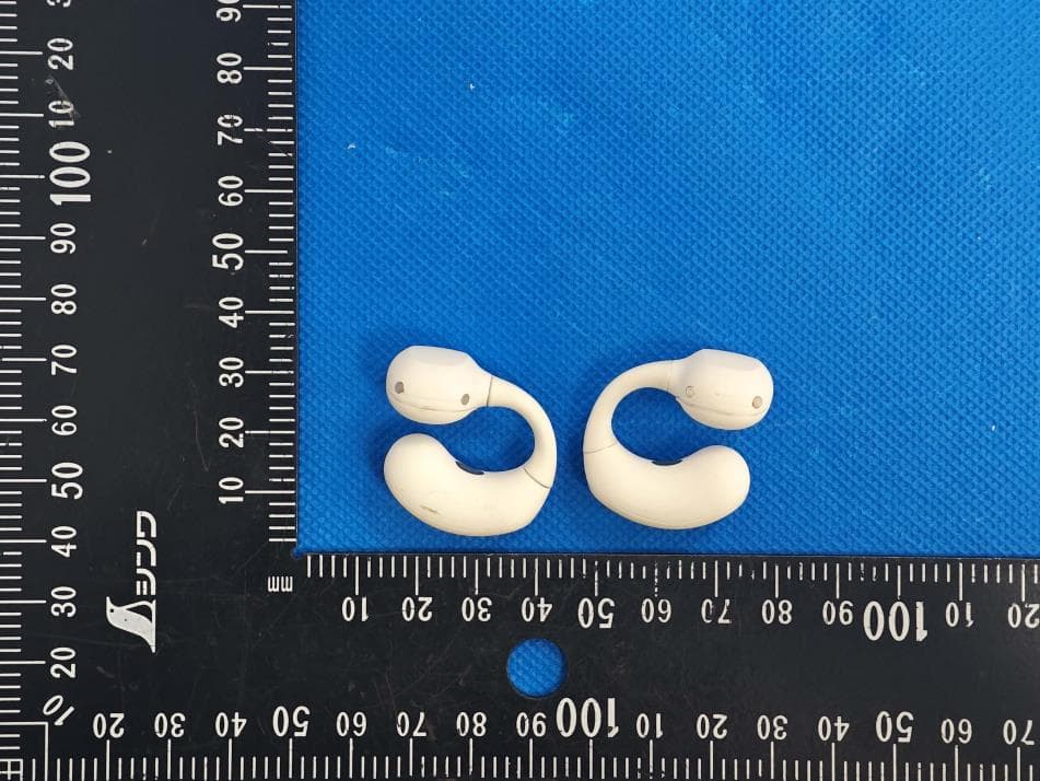
2AZXT-FA006
Sep 05, 2025ACECLIP Pro Wireless Earbuds
Equipment Class
DTS - Digital Transmission System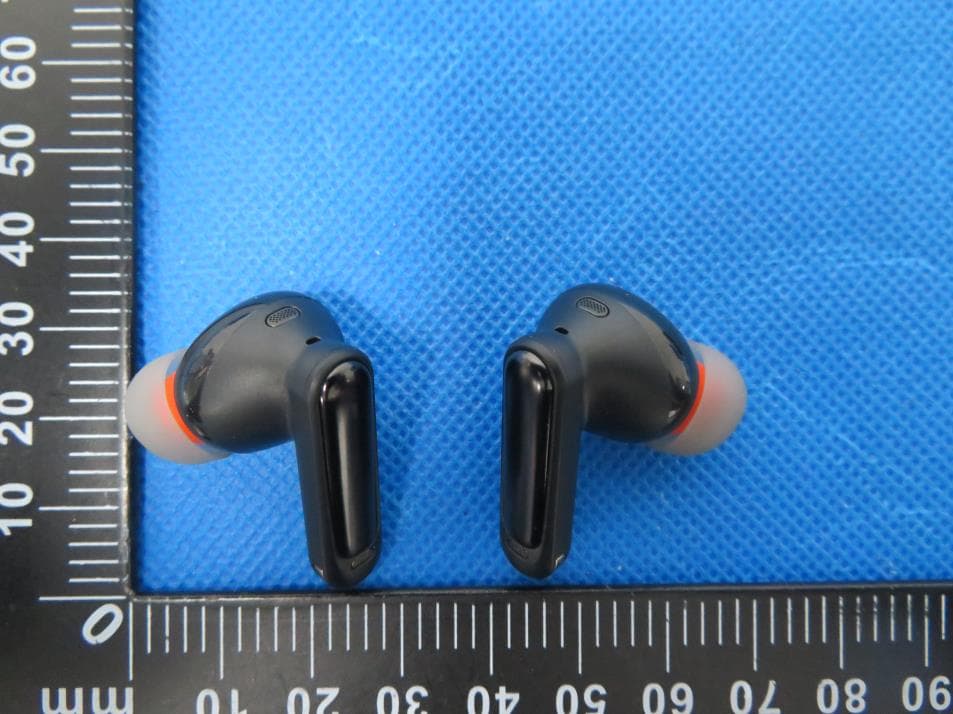
2AZXT-W1
Aug 29, 2024Active Noise Cancelling true wireless earbuds
Equipment Class
DSS - Part 15 Spread Spectrum Transmitter
2AZXT-AF2106
Jul 07, 2024Wireless Earbuds
Equipment Class
DSS - Part 15 Spread Spectrum Transmitter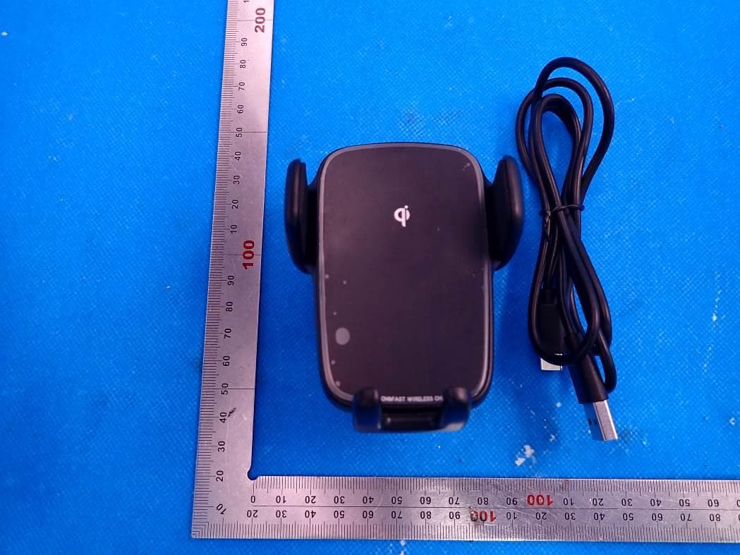
2AZXT-AF2102
Jul 25, 2021Wireless charging stand
Equipment Class
DCD - Part 15 Low Power Transmitter Below 1705 kHz