2AZXW-LF-WM03WiFi module
Guangdong Yuefang Technology Co. Ltd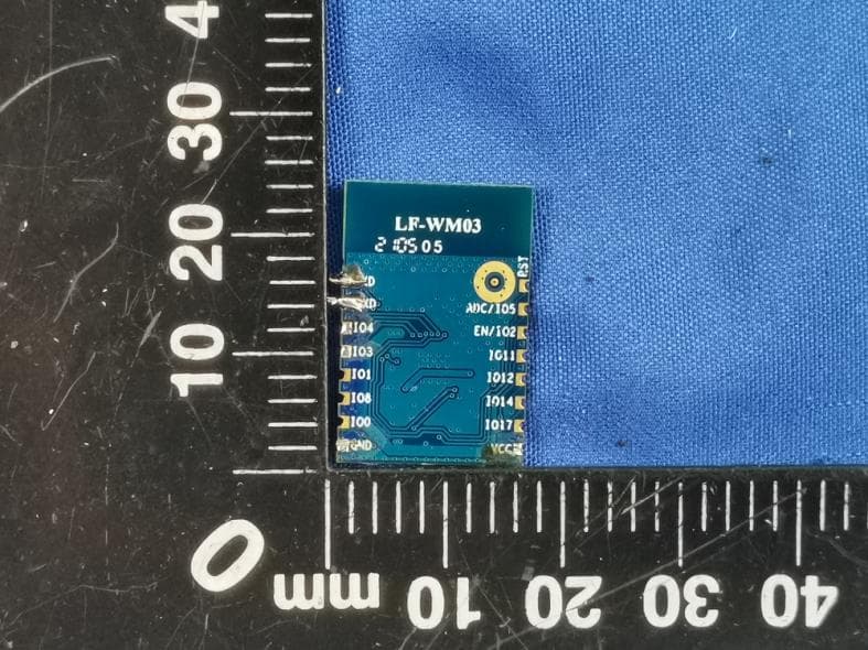
Click to zoom
Application Details
- Equipment Class
- DTS - Digital Transmission System
- Date of Grant
- Jul 01, 2021
- Application Purpose
- Original Equipment
- Date of Application
- Jun 30, 2021
- Equipment Note
- WiFi module
- Frequency Range
- 2412.00000000 - 2462.00000000
- Country
- China
Documents & Files
Document Text
Text extracted from the exhibit documents filed with the FCC. Open a document above to read the original.
Users Manual
© 2020 LeapFive Inc. Confidential Page 1 GuangDong LeapFive Technology Co.,Ltd., specifications Module name:LF-WM03 module Version number:LF_WM_FW_1.0.0 Days: 2020-08-20 © 2020 LeapFive Inc. Confidential Page 2 Outline The name of the module LF-WM03 characteristic Supports the 802.11 b/g/n standard, frequency range 2400M to 2483.5MHz Contains 276KB SRAM/128KB ROM/1Kb eFuse Operating voltage:DC 2.5 V to 3.6 V Wi-Fi-related features Support for IEEE 802.11 b/g/n standard 20MHz bandwidth Supports STA, SoftAP and sniffer mode PCB onboard antenna peripheral 2*UART 1*I2C 5*PWM 1*SPI 1*SDIO 1*12bit ADC 1*10bit DAC 13*GPIO Scenario Smart Home / Home Appliances Smart transportation Smart lighting Intelligent security Industrial automation © 2020 LeapFive Inc. Confidential Page 3 Directory Outline ...................................................... 2 1. Introduction: .............................................. 4 1.1 Package size ........................................... 4 1.2 Pin definition ......................................... 5 2. Electrical parameters ...................................... 7 2.1 working conditions ..................................... 7 2.2 Hardware and software parameters ....................... 8 2.3 Power parameters ....................................... 8 3 RF parameters ............................................. 10 3.1 RX features ........................................... 10 3.2 TX features ........................................... 11 4. MCU ..................................................... 11 4.1 CPU .................................................. 11 4.2 storage ............................................... 12 4.3 Crystal ............................................... 12 5. Assembly information and production guidance ............... 13 5.1 Assembly dimensions ................................... 13 5.2 PCB antenna clearance area ............................ 13 5.3 Production precautions ................................ 14 © 2020 LeapFive Inc. Confidential Page 4 1. Introduction: The LF-WM03 module is alow-cost, high-performance WIFI module based on the LF686C(32- bit RISC CPU with FPU) to create a cost-effective IoT module for customers. Figure 1 shows the hardware block diagram of the LF-WM03 module, consisting of the following three major parts: 32-bit RISC-V core CPU WiFi RF module Enrich peripherals Figure 1 LF-WM03 hardware block diagram thereinto: 32-bit RISC-V core CPU with up to 192MHz operating frequency Internal integration 276KB SRAM,128KB ROM Supports high-speed UART,I2C,SPI,PWM,andmultiple GPIO portes Enter typical voltage:3.3V 1.1 Package size The LF-WM03 patch module has a dimensions of (16.00±0.10) mm x (24.00±0.10) mm x (3.00±0.10)mm. The exact dimensions are shown in Table 1. © 2020 LeapFive Inc. Confidential Page 5 Table 1 Module Size Reference Table Long Wide High PAD size PIN foot spacing 24mm 16mm 3.0mm 1*1.4mm 2mm The LF-WM03 module is designed in a stamp package as shown in Figure 2 for easy commissioning, easy disassembly and a variety of options for customer design. A total of 16 pins are drawn, with a 2mm pin spacing and evenly distributed on both sides of the module. 1.2 Pin definition Figure 2 Stamp hole package dimensions 1.2.1 Pin distribution The pin distribution of the LF-WM03 patch module is shown in Figure 3, resulting in a total of 16 feet, 13 GPIO, and one power, ground, and reset pin each. © 2020 LeapFive Inc. Confidential Page 6 Figure 3 LF-WM03 Pin Definition 1.2.2 Pin definition The LF-WM03 pin definition is shown in Table 2. Table 2 LF-WM03 Pin Definition Table Serial number Pin name Description of the function 1 RST Reset the foot 2 IO_05 SDIO, SPI, I2C, UART, PWM, GPIO 3 IO_02 SDIO, SFLASH, SPI, I2C, UART, PWM, GPIO 4 IO_11 SPI, I2C, UART, PWM, AUXADC, GPIO 5 IO_12 SPI, I2C, UART, PWM, AUXADC, GPIO 6 IO_14 SPI, I2C, UART, PWM, AUXADC, GPIO 7 IO_17 SFLASH, SPI, I2C, UART, PWM, GPIO 8 VCC 3.3V © 2020 LeapFive Inc. Confidential Page 7 Serial number Pin name Description of the function 9 GND GND 10 IO_00 SDIO, SFLASH, SPI, I2C, UART, PWM, GPIO 11 IO_08 SPI, I2C, UART, PWM, AUXADC, GPIO 12 IO_01 SDIO, SFLASH, SPI, I2C, UART, PWM, GPIO 13 IO_03 SDIO, SPI, I2C, UART, PWM, GPIO 14 IO_04 SDIO, SPI, I2C, UART, PWM, GPIO 15 IO_07 SPI, I2C, UART, PWM, AUXADC, GPIO 16 IO_16 SPI, I2C, UART, PWM, GPIO Note: IO08 port needs to be pulled up when downloading burning, not when using it. 2. Electrical parameters 2.1 working conditions The LF-WM03 module recommends working parameters as shown in Table 3. Table 3 recommends working conditions Parameter Name Minimum Typical value Maximum Unit Store the temperature / –40 °C 25°C 125 °C / Operating temperature / –20 °C 25°C 85 °C / Supply voltage VDD 2.5 3.3 3.6 V In-logic low level V IL –0.3 / 0.25 VDD V In-logic high level V IH 0.75 VDD / VDD + 0.3 V Output logic low level V OL / / 0.1 VDD V Output logic high level V OH 0.8 VDD / / V The maximum rating for electrostatic protection for the LF-WM03 module is shown in Table 4, and exceeding the maximum rating can cause permanent damage to the hardware. Table 4 Maximum rating for electrostatic protection Parameter Minimum Maximum Unit ESD Protection (HBM) / 2000 V © 2020 LeapFive Inc. Confidential Page 8 2.2 Hardware and software parameters Type Parameter Illustrate Wireless parameters WIFI protocol 802.11 b/g/n Frequency range 2400M ~ 2483.5MHz Hardware parameters The data interface UART/I2C/SPI/IR remote control GPIO/PWM Operating voltage 2.5 V ~ 3.6 V Operating current The average current is 80mA The current is supplied Minimum 500mA Operating temperature –20°C ~ 85 °C Package size (16.00±0.10) mm x (24.00±0.10) mm x (3.00±0.10) mm Software parameters Wireless network mode Supports STA, SoftAP, and sniffer mode Security mechanisms WPA/WPA2 Type of encryption WEP/TKIP/AES Upgrade the firmware Local serial burn / cloud upgrade / host download burn Software developme…
Text truncated - open the document above for the full version.
Attestation Statements
Single Modular approval Declaration letter We ,Guangdong Yuefang Technology Co. Ltd apply single modular approval for Product Name: WiFi module Model: LF-WM03 FCC ID: 2AZXW- LF-WM03 According to 996369 D01 Module Equip Auth Guide v01r04 and 15.212 requirement: 1) The radio elements must have the radio frequency circuitry shielded. Physical components and tuning capacitor(s) may be located external to the shield, but must be on the module assembly; Answer :Yes ;Shielded . 2) The module must have buffered modulation/data inputs to ensure that the device will comply with Part 15 requirements with any type of input signal; Answer :Yes ; All inputs to the modules are buffered through logic or microprocessor inputs. 3)The modular transmitter must have its own power supply regulation. Answer :Yes ;A low drop out regulator is used for modular power supply regulation. 4) The module must contain a permanently attached antenna, or contain a unique antenna connector, and be marketed and operated only with specific antenna(s), per Sections15.203, 15.204(b), 15.204(c), 15.212(a), 2.929(b); Answer :Yes ;Device is equipped with PCB antenna. (5) The module must demonstrate compliance in a stand-alone configuration; Answer :Yes;distance between modular and all AEs are bigger than 10cm ,refer to setup photo. (6) The module must be labeled with its permanently affixed FCC ID label, or use an electronic display (See KDB Publication 784748 about labeling requirements); Answer :Yes ;The modular has a permanent fixed label, and below statement was listed in the User Manual ; The host device must be labeled to display the FCC ID of the module “Contains FCC ID: 2AZXW-LF-WM03” (7) The module must comply with all specific rules applicable to the transmitter including all the conditions provided in the integration instructions by the grantee; Answer :Yes ;The module comply with all specific rules applicable to the transmitter including all the conditions provided in the integration instructions by the grantee, Refer to test report and user manual . (8) The module must comply with RF exposure requirements Answer :Yes ;Transmitter meets MPE calculation of 47 CFR 1.1307 . Refer to MPE Reports and Refer to modular installation manual Please contact me if you have any further questions. Thanks for your attention. Best Regards, <Signature> Name :Jerry Wen Title: Product Manager Applicant Company:Guangdong Yuefang Technology Co. Ltd
Attestation Statements
Compliance list INTEGRATION INSTRUCTIONS for 996369 D03 OEM the and 996369 D03 OEM by Sections 2.2 through 2.10. Requirement Yes N/A Comment 2.2 List of applicable FCC rules List the FCC rules that are applicable to the modular transmitter. These are the rules that specifically establish the bands of operation, the power, spurious emissions, and operating fundamental frequencies. DO NOT list compliance to unintentional-radiator rules (Part 15 Subpart B) since that is not a condition of a module grant that is extended to a host manufacturer. See also Section 2.10 below concerning the need to notify host manufacturers that further testing is required.3 YES Refer to instruction FCC standards: FCC CFR Title 47 Part 15 Subpart C Section 15.247 2.3 Summarize the specific operational use conditions Describe use conditions that are applicable to the modular transmitter, including for example any limits on antennas, etc. For example, if point-to-point antennas are used that require reduction in power or compensation for cable loss, then this information must be in the instructions. If the use condition limitations extend to professional users, then instructions must state that this information also extends to the host manufacturer’s instruction manual. In addition, certain information may also be needed, such as peak gain per frequency band and minimum gain, specifically for master devices in 5 GHz DFS bands. YES Refer to instruction Integral antenna with antenna gain 1.5dBi 2.4 Limited module procedures If a modular transmitter is approved as a “limited module,” then the module manufacturer is responsible for approving the host environment that the limited module is used with. The manufacturer of a limited module must describe, both in the filing and in the installation instructions, the alternative means that the limited module manufacturer uses to verify that the host meets the necessary requirements to satisfy the module limiting conditions. A limited module manufacturer has the flexibility to define its alternative method to address the conditions that limit the initial approval, such as: shielding, minimum N/A Not applicable signaling amplitude, buffered modulation/data inputs, or power supply regulation. The alternative method could include that the limited module manufacturer reviews detailed test data or host designs prior to giving the host manufacturer approval. This limited module procedure is also applicable for RF exposure evaluation when it is necessary to demonstrate compliance in a specific host. The module manufacturer must state how control of the product into which the modular transmitter will be installed will be maintained such that full compliance of the product is always ensured. For additional hosts other than the specific host originally granted with a limited module, a Class II permissive change is required on the module grant to register the additional host as a specific host also approved with the module. 2.5 Trace antenna designs For a modular transmitter with trace antenna designs, see the guidance in Question 11 of KDB Publication 996369 D02 FAQ – Modules for Micro-Strip Antennas and traces. The integration information shall include for the TCB review the integration instructions for the following aspects: layout of trace design, parts list (BOM), antenna, connectors, and isolation requirements.4 a) Information that includes permitted variances (e.g., trace boundary limits, thickness, length, width, shape(s), dielectric constant, and impedance as applicable for each type of antenna); b) Each design shall be considered a different type (e.g., antenna length in multiple(s) of frequency, the wavelength, and antenna shape (traces in phase) can affect antenna gain and must be considered); c) The parameters shall be provided in a manner permitting host manufacturers to design the printed circuit (PC) board layout; d) Appropriate parts by manufacturer and specifications; e) Test procedures for design verification; and f) Production test procedures for ensuring N/A Not applicable compliance. The module grantee shall provide a notice that any deviation(s) from the defined parameters of the antenna trace, as described by the instructions, require that the host product manufacturer must notify the module grantee that they wish to change the antenna trace design. In this case, a Class II permissive change application is required to be filed by the grantee, or the host manufacturer can take responsibility through the change in FCC ID (new application) procedure followed by a Class II permissive change application. 2.6 RF exposure considerations It is essential for module grantees to clearly and explicitly state the RF exposure conditions that permit a host product manufacturer to use the module. Two types of instructions are required for RF exposure information: (1) to the host product manufacturer, to define the application conditions (mobile, portable – xx cm from a person’s body); and (2) additional text needed for the host product manufacturer to provide to end users in their end-product manuals. If RF exposure statements and use conditions are not provided, then the host product manufacturer is required to take responsibility of the module through a change in FCC ID (new application). YES Refer to instruction The modular can be installed or integrated in mobile or fix devices only. This modular cannot be installed in any portable device if without any further certification,such as C2PC with SAR . This modular complies with FCC RF radiation exposure limits set forth for an uncontrolled environment. This transmitter must not be co-located or operating in conjunction with any other antenna or transmitter. This modular must be installed and operated with a minimum distance of 20 cm between the radiator and user body. 2.7 Antennas A list of antennas included in the application for certification must be provided in the instructions. For modular transmitters approved as limited m…
Text truncated - open the document above for the full version.
Cover Letter(s)
DATE: 2021/06/01 Equipment Autorisation Division Federal Communications Commission 7435 Oakland Mills Road Columbia, MD 21046 FCC ID: _2AZXW- LF-WM03__ Product Name: _ WiFi module __ Request for Confidentiality Pursuant to Sections 0.457 and 0.459 of the commission’s rules, we hereby request that the following documents be held confidential: (List here the documents for which you are seeking confidentiality – for example ...) Schematics Block diagram Operation description These materials contain trade secrets and proprietary information and are not customarily released to the public. The public disclosure of this information might be harmful to the company and provide unjustified benefits to our competitors. <Signature> Name :Jerry Wen Title: Product Manager Applicant Company:Guangdong Yuefang Technology Co. Ltd
Cover Letter(s)
DATE: 2021/06/01 Federal Communications Commission Authorization & Evaluation Division 7345 Oakland Mills Road Columbia, Maryland 21046 RE: LETTER OF AGENT AUTHORIZATION To Whom It May Concern: We, the undersigned, hereby authorize Compliance Testing, LLC to act on our behalf in all matters relating to application for equipment authorization, including the signing of all documents relating to these matters. We also hereby certify that no party to the application authorized hereunder is subject to the denial of benefits, including FCC benefits, pursuant to Section 5301 of the Anti-Drug Abuse Act of 1988, 21 U.S.C.853(a). Sincerely, <Signature> Name :Jerry Wen Title: Product Manager Applicant Company:Guangdong Yuefang Technology Co. Ltd
External Photos
Photos of the EUT
ID Label/Location Info
Label location: WiFi module Model: LF-WM03 FCC ID: 2AZXW-LF-WM03 IC: 27307-LFWM03
Internal Photos
Antenna
RF Exposure Info
RF Exposure evaluation FCC ID:2AZXW-LF-WM03 Reference According to §1.1307(b)(1), systems operating under the provisions of this section shall be operated in a manner that ensures that the public is not exposed to radio frequency energy level in excess of the Commission’s guidelines. According to §1.1310 and §2.1091 RF exposure is calculated. KDB447498 D01: Mobile and Portable Devices RF Exposure Procedures and Equipment Authorization Policies 2. Limit Limits for Maximum Permissible Expo sure (MPE)/Controlled Exposure Frequency Range(MHz) Electric Field Strength(V/m) Magnetic Field Strength(A/m) Power Densit y (m W/cm²) Averaging Time (m inute) Li mits for Occupational/Controlled Exposure 6140.3 – 3.0 1.63 (100) * 6 4.89/f (900/f1842/f3.0 – 30 2 )*6 0.16 3 1.061.430 – 300 6 300 – 1500 / /f/3006 1500 – 100,000 / / 5 6 Lim its for Maximum Permissible Exposure (MPE)/Uncontrolled Exposure Frequency Range(MHz) Electric Field Strength(V/m) Magnetic Field Strength(A/m) Power Densit y (m W/cm²) Averaging Time (m inute) Li mits for Occupational/Controlled Exposure 6140.3 – 3.0 1.63 (100) * 30 2.19/f824/f3.0 – 30(180/f 2 )*30 0.07 327.530 – 3000.2 30 300 – 1500 / /f/1500 30 1500 – 100,000 / /1.0 30 F=freque ncy in MHz *=Plane-wave equivalent power density 3.MPE Calculation Method Predication o f MPE limit at a given distance Equation from page 18 of OET Bulletin 65, Edition 97-01 S=PG/4πR² Where: S= power density P=power input to antenna G=power gain of the antenna in the direction of interest relative to an isotropic radiator R=distance to the center of radiation of the antenna 4.Result As declar ed by the Applicant, the EUT is a wireless device used in a fix application, at least 20 cm from any body part of the user or nearby persons; from the maximum EUT RF output power, the minimum separation distance, r =20cm, as well as the gain of the used antenna is 1.5 dBi for 2.4GHz and , the RF power density can be obtained. For 2.4GHz wifi Mode Max. Output Power (dBm) Max. Output Power ( mW) Antenna Gain (Nu meric) Power Den sity at 20 cm (mW/ cm 2 ) Power Den sity Limit F CC (mW/ cm 2 ) Test Re sults 802.11b 19.85 96.6051 1.4125 0.0271 1 .0000 PASS 802.11g 21.21 132.1296 1.4125 0.0371 1 .0000 PASS 802.11n20 21.19 131.5225 1.4125 0.0370 1 .0000 PASS 5.Conclusion The SAR evaluation is n ot required.
Test Report
Shenzhen CTL Testing Technology Co., Ltd. Tel: +86-755-89486194 E-mail: [email protected] TEST REPORT FCC PART 15.247 Report Reference No. ................ : CTL2104143031-WF Compiled by: ( position+printed name+signature) Happy Guo (File administrators) Tested by: ( position+printed name+signature) Gary Gao (Test Engineer) Approved by: ( position+printed name+signature) Ivan Xie (Manager) Product Name ............................ : WiFi module Model/Type reference ................ : LF-WM03 List Model(s) ............................... : N/A Trade Mark .................................. : LeapFive FCC ID ......................................... : 2AZXW- LF-WM03 Applicant’s name ....................... : Guangdong Yuefang Technology Co. Ltd Address of applicant ................. : 13/F,#9-B1, Shenzhen Bay Eco-Technology Park, Nanshan Disc, Shenzhen, Guangdong Province, China Test Firm ..................................... : Shenzhen CTL Testing Technology Co., Ltd. Address of Test Firm ................. : Floor 1-A, Baisha Technology Park, No.3011, Shahexi Road, Nanshan District, Shenzhen, China 518055 Test specification ....................... : Standard ...................................... : 47 CFR FCC Part 15 Subpart C 15.247 TRF Originator ............................. : Shenzhen CTL Testing Technology Co., Ltd. Master TRF .................................. : Dated 2011-01 Date of receipt of test item ........ : Apr. 28, 2021 Date of sampling ........................ : Apr. 28, 2021 Date of Test Date ........................ : Apr. 28, 2021–May. 10, 2021 Date of Issue .............................. : May. 11, 2021 Result .......................................... : Pass Shenzhen CTL Testing Technology Co., Ltd. All rights reserved. This publication may be reproduced in whole or in part for non-commercial purposes as long as the Shenzhen CTL Testing Technology Co., Ltd. is acknowledged as copyright owner and source of the material. Shenzhen CTL Testing Technology Co., Ltd. takes no responsibility for and will not assume liability for damages resulting from the reader's interpretation of the reproduced material due to its placement and context. V1.0 Page 2 of 31 Report No.: CTL2104143031-WF TEST REPORT Test Report No. : CTL2104143031-WF May. 11, 2021 Date of issue Equipment under Test : WiFi module Sample No. CTL210414303-1-S001 Model /Type : LF-WM03 Listed Models : N/A Applicant : Guangdong Yuefang Technology Co. Ltd Address : 13/F,#9-B1, Shenzhen Bay Eco-Technology Park, Nanshan Disc, Shenzhen, Guangdong Province, China Manufacturer : Huizhou GaoshengdaTechnology Co. Ltd Address : No.2, Jin-da Road, Huinan High-tech Industrial Park, Hui-ao Avenue, Huizhou City, Guangdong Province, China Test result Pass * * In the configuration tested, the EUT complied with the standards specified page 5. The test results presented in this report relate only to the object tested. This report shall not be reproduced, except in full, without the written approval of the issuing testing laboratory. V1.0 Page 3 of 31 Report No.: CTL2104143031-WF ** Modified History ** Revisions Description Issued Data Report No. Remark Version 1.0 Initial Test Report Release 2021-05-11 CTL2104143031-WF Tracy Qi V1.0 Page 4 of 31 Report No.: CTL2104143031-WF Table of Contents Page 1. SUMMARY .................................................................................................................................................................... 5 1.1. TEST STANDARDS ........................................................................................................................................................... 5 1.2. TEST DESCRIPTION .............................................................................................................................................................. 5 1.3. TEST FACILITY ..................................................................................................................................................................... 6 1.4. STATEMENT OF THE MEASUREMENT UNCERTAINTY ..................................................................................................................... 6 2. GENERAL INFORMATION ............................................................................................................................................... 8 2.1. ENVIRONMENTAL CONDITIONS .............................................................................................................................................. 8 2.2. GENERAL DESCRIPTION OF EUT ............................................................................................................................................ 8 2.3. DESCRIPTION OF TEST MODES AND TEST FREQUENCY ................................................................................................................ 9 2.4. EQUIPMENTS USED DURING THE TEST ................................................................................................................................... 11 2.5. RELATED SUBMITTAL(S) / GRANT (S) .................................................................................................................................... 11 2.6. MODIFICATIONS ............................................................................................................................................................... 11 3. TEST CONDITIONS AND RESULTS ................................................................................................................................. 12 3.1. CONDUCTED EMISSIONS TEST ............................................................................................................................................. 12 3.2. RADIATED EMISSIONS AND BAND EDGE ................................................................................................................................. 15 3.3. MAXIMUM CONDUCTED OUTPUT POWER ...........................................…
Text truncated - open the document above for the full version.
Test Report
V1.0 Page 1 of 30 Report No.: CTL2104143031-WF Appendix for 15.247 1. Bandwidth 1.1 Test Result Test Mode Frequency (MHz) TX Type ANT No. 6dB Bandwidth Verdict Test Result (MHz) Limits (MHz) 802.11b 2412 SISO 1 9.097 ≥0.5 PASS 2437 SISO 1 9.105 ≥0.5 PASS 2462 SISO 1 9.106 ≥0.5 PASS 802.11g 2412 SISO 1 16.436 ≥0.5 PASS 2437 SISO 1 16.389 ≥0.5 PASS 2462 SISO 1 16.447 ≥0.5 PASS 802.11n(HT20) 2412 SISO 1 17.081 ≥0.5 PASS 2437 SISO 1 16.989 ≥0.5 PASS 2462 SISO 1 17.217 ≥0.5 PASS Test Mode Frequency (MHz) TX Type ANT No. 99% Occupied Bandwidth Test Result (MHz) 802.11b 2412 SISO 1 13.373 Only for Report Use 2437 SISO 1 13.430 Only for Report Use 2462 SISO 1 13.383 Only for Report Use 802.11g 2412 SISO 1 17.050 Only for Report Use 2437 SISO 1 17.055 Only for Report Use 2462 SISO 1 16.941 Only for Report Use 802.11n(HT20) 2412 SISO 1 17.720 Only for Report Use 2437 SISO 1 17.697 Only for Report Use 2462 SISO 1 17.703 Only for Report Use 1.2 Test Graph - 6dB Bandwidth V1.0 Page 2 of 30 Report No.: CTL2104143031-WF V1.0 Page 3 of 30 Report No.: CTL2104143031-WF V1.0 Page 4 of 30 Report No.: CTL2104143031-WF V1.0 Page 5 of 30 Report No.: CTL2104143031-WF V1.0 Page 6 of 30 Report No.: CTL2104143031-WF 1.3 Test Graph - 99% Occupied Bandwidth V1.0 Page 7 of 30 Report No.: CTL2104143031-WF V1.0 Page 8 of 30 Report No.: CTL2104143031-WF V1.0 Page 9 of 30 Report No.: CTL2104143031-WF V1.0 Page 10 of 30 Report No.: CTL2104143031-WF V1.0 Page 11 of 30 Report No.: CTL2104143031-WF 2. Maximum Conducted Output Power 2.1 Test Result Test Mode Frequency (MHz) Tx Type Measured Peak Output Power (dBm) Limits (dBm) Verdict Ant 1 802.11b 2412 SISO 19.85 30 PASS 2437 SISO 18.84 30 PASS 2462 SISO 17.10 30 PASS 802.11g 2412 SISO 21.21 30 PASS 2437 SISO 20.37 30 PASS 2462 SISO 18.87 30 PASS 802.11n(HT20) 2412 SISO 21.19 30 PASS 2437 SISO 20.45 30 PASS 2462 SISO 18.97 30 PASS 2.2 Test Graph V1.0 Page 12 of 30 Report No.: CTL2104143031-WF V1.0 Page 13 of 30 Report No.: CTL2104143031-WF V1.0 Page 14 of 30 Report No.: CTL2104143031-WF V1.0 Page 15 of 30 Report No.: CTL2104143031-WF V1.0 Page 16 of 30 Report No.: CTL2104143031-WF 3. Maximum Power Spectral Density (PSD) 3.1 Test Result Test Mode Frequency (MHz) Tx Type Maximum Power Spectral Density (dBm/3KHz) Limits (dBm/3kHz) Verdict Ant 1 802.11b 2412 SISO -5.92 ≤8 PASS 2437 SISO -6.77 ≤8 PASS 2462 SISO -8.52 ≤8 PASS 802.11g 2412 SISO -11.97 ≤8 PASS 2437 SISO -12.52 ≤8 PASS 2462 SISO -14.52 ≤8 PASS 802.11n(HT20) 2412 SISO -11.66 ≤8 PASS 2437 SISO -13.21 ≤8 PASS 2462 SISO -14.90 ≤8 PASS 3.2 Test Graph V1.0 Page 17 of 30 Report No.: CTL2104143031-WF V1.0 Page 18 of 30 Report No.: CTL2104143031-WF V1.0 Page 19 of 30 Report No.: CTL2104143031-WF V1.0 Page 20 of 30 Report No.: CTL2104143031-WF V1.0 Page 21 of 30 Report No.: CTL2104143031-WF 4. Unwanted Emissions in Non-restricted Frequency Bands 4.1 Test Result Test Mode Frequency (MHz) TX Type ANT No. Spurious Conducted Emission (dBm) Limits (dBm) Verdict 802.11b 2412 SISO 1 Refer to test graph -11.52 PASS 2437 SISO 1 Refer to test graph -11.52 PASS 2462 SISO 1 Refer to test graph -11.52 PASS 802.11g 2412 SISO 1 Refer to test graph -17.06 PASS 2437 SISO 1 Refer to test graph -17.06 PASS 2462 SISO 1 Refer to test graph -17.06 PASS 802.11n(HT20) 2412 SISO 1 Refer to test graph -17.10 PASS 2437 SISO 1 Refer to test graph -17.10 PASS 2462 SISO 1 Refer to test graph -17.10 PASS 4.2 Test Graph V1.0 Page 22 of 30 Report No.: CTL2104143031-WF V1.0 Page 23 of 30 Report No.: CTL2104143031-WF V1.0 Page 24 of 30 Report No.: CTL2104143031-WF V1.0 Page 25 of 30 Report No.: CTL2104143031-WF V1.0 Page 26 of 30 Report No.: CTL2104143031-WF V1.0 Page 27 of 30 Report No.: CTL2104143031-WF V1.0 Page 28 of 30 Report No.: CTL2104143031-WF V1.0 Page 29 of 30 Report No.: CTL2104143031-WF V1.0 Page 30 of 30 Report No.: CTL2104143031-WF
Test Setup Photos
FCC ID: 2AZXW-LF -WM03 IC : 27307-LFWM03 Test Setup Photos of the EUT
Contact Information
Applicant
Wen Jerry(Product Manager)
Test Firm
Shenzhen CTL Testing Technology Co., Ltd.Tracy Qi
[email protected]86-755-89486194
Technical Specifications
| # | Rule Parts | Frequency Range | Power Output |
|---|---|---|---|
| 1 | 15C | 2.41 GHz - 2.46 GHz | 132.13 mW |