2BA3X25LEUS1128Dc Tubular Motor
UBlockout, Inc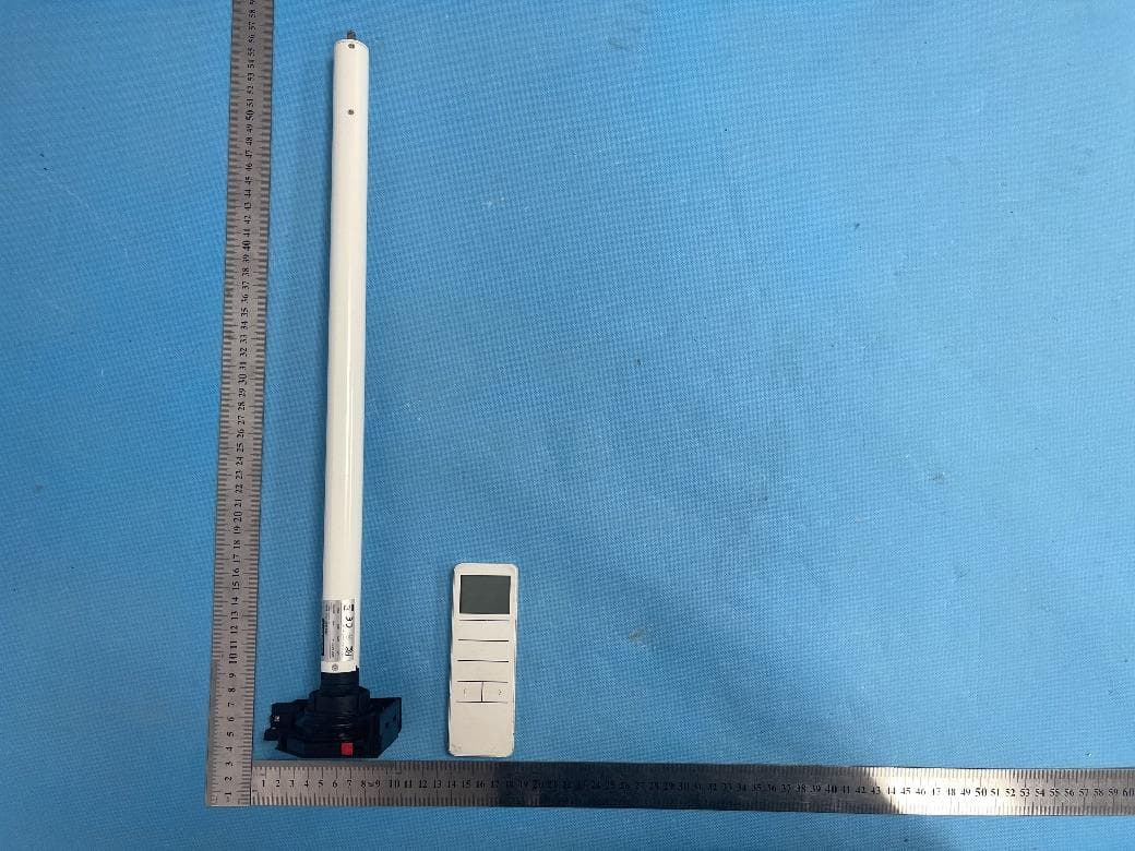
Click to zoom
Application Details
- Equipment Class
- DSR - Part 15 Remote Control/Security Device Transceiver
- Date of Grant
- Jul 23, 2023
- Application Purpose
- Original Equipment
- Date of Application
- Jul 23, 2023
- Equipment Note
- Dc Tubular Motor
- Frequency Range
- 433.92000000 - 433.92000000
- Company
- UBlockout, Inc
- Country
- United States
Documents & Files
Document Text
Text extracted from the exhibit documents filed with the FCC. Open a document above to read the original.
Users Manual
* For more motor models and specific torque, please refer to the nameplate. Caution 1. Do not expose motor to humid or extreme temperature conditions. 2. Do not drill into motor. 3. Do not cut the antenna and keep it clear from metal objects. 4. Do not allow children to play with this device. 5. If power cable or connector is damaged, do not use. 6. Ensure correct crown and drive adaptor are used. 7. Ensure power cable and aerial is clear and protected from moving parts. 8. Cable routed through walls shall be properly isolated. 9. Motor is to be mounted in horizontal position only. 10. Before installation, remove unnecessary cords and disable equipment not needed for powered operation. 11. Installation and programming to be performed by a qualified professional, use or modification outside the scope of this instruction may void warranty. Motor Installation Drive tube Drive tube Step 1 Cut drive tube to required length.Step 2 Ensure tube edge is clean and burr-free. Charging Instructions Micro-USB charging: 5V This motor has a built in Li-ion battery pack with integrated charge management. Max power input for recharging: 5V 2A. Before first use please charge motor for 6 hours. Using 5V charger (most phones charger is 5V ) . During operation, when the motor starts, the buzzer will beep 10 times, indicating a low-voltage alarm and needs to be charged. During operation, the voltage was detected to be too low, the battery was about to run out, the battery stopped running and needed to be recharged. Micro-USB Port Rechargeable Battery Portable Charger For Emergency Usage Blinking red: Low battery alert Blinking green: Charging is processing Solid green: full charged Step 3 Mount correct crown & drive adapter on the motor. Make sure drive adapter fits firmly and crown rotates freely. Step 4 Align the notches on the crown and drive adapter with the drive tube, slide and fit the motor into drive tube. Mount idler and bracket on both ends. Drive Adapter Crown Circlip Bracket Bracket 0 1 0 1 DM25LEU/S InstructionA-08 Attention Fields of Application Features The motor is suitable for motorization of roller blinds. Never drop, knock, drill or submerge the motor. Keep the power cable in right position as following. Important safety instructions to be read before installation. Incorrect installation can lead to serious injury and will void manufacturer’s liability and warranty. Built-in Receiver Jog & Tilt Built-in Lithium Battery Scan and Program Status Feedback Switch Direction Stall Protection Program Button Reset to Factory Mode Memorized Setting Electronic Limit Preferred Stop Position Speed Regulation Scene Control Specifications Working temperature: -10°C ~ +50°C Input Voltage: USB 5V 1A / USB 5V 2A Radio Frequency: 433.925MHz Maximum Running Time: 6 minutes SAFETY NOTE 1. This appliance can be used by children aged from 8 years and above and persons with reduced physical, sensory or mental capabilities or lack of experience and knowledge if they have been given supervision or instruction concerning use of the appliance in a safe way and understand the hazards involved. 2. Children shall not play with the appliance. 3. Cleaning and user maintenance shall not be made by children without supervision. 4. If the supply cord is damaged, it must be replaced by the manufacturer, its service agent or similarly qualified persons in order to avoid a hazard. 5. WARNING: the drive shall be disconnected from its power source during cleaning, maintenance and when replacing parts. 6. The instructions shall state that the A-weighted emis sion sound pressure level of the drive is equal to or less than 70 dB(A), e.g. by writing LpA ≤ 70 dB(A). 7. The mass and the dimension of the driven part shall be compatible with the rated torque and rated operating time. 8. The type of driven part the drive is intended for. 9. WARNING: Important safety instructions. It is important for the safety of persons to follow these instructions. Save these instructions. 10. Do not allow children to play with fixed controls. Keep remote controls away from children. 11. Frequently examine the installation for imbalance and signs of wear or damage to cables and springs. Do not use if repair or adjustment is necessary. 12. Watch the moving shutter and keep people away until the shutter is completely closed. 13. WARNING: Important safety instructions. Follow all instructions, since incorrect installation can lead to severe injury. 14. Before installing the drive, remove any unnecessary cords and disable any equipment not needed for powered operation. Do not dispose of in general waste. Please recycle batteries and damaged electrical products appropriately. -1--2- FCC Warning Note: This equipment has been tested and found to comply with the limits for a Class B digital device, pursuant to part 15 of the FCC Rules. These limits are designed to provide reasonable protection against harmful interference in a residential installation. This equipment generates, uses and can radiate radio frequency energy and, if not installed and used in accordance with the instructions, may cause harmful interference to radio communications. However, there is no guarantee that interference will not occur in a particular installation. If this equipment does cause harmful interference to radio or television reception, which can be determined by turning the equipment off and on, the user is encouraged to try to correct the interference by one or more of the following measures: —Reorient or relocate the receiving antenna. —Increase the separation between the equipment and receiver. —Connect the equipment into an outlet on a circuit different from that to which the receiver is connected. —Consult the dealer or an experienced radio/TV technician for help. NOTE 2: Any changes or modifications to this unit not expressly approved by the party responsible for compliance could void the user's authority to operate the equipment.
Attestation Statements
UBlockout, Inc 10580 Newkirk Street Suite 301, Dallas, Texas 75220, United States Date: 2023-07-18 Federal Communications Commission Authorization and Evaluation Division 7435 Oakland Mills Road Columbia, MD 21046 Ref: Attestation Statements Part 2.911(d) (5) (i) Filing SUBJECT: FCC Application for FCC ID: 2BA3X25LEUS1128 To Whom It May Concern: UBlockout, Inc certifies that the equipment for which authorization is sought is not “covered” equipment prohibited from receiving an equipment authorization pursuant to section 2.903 of the FCC rules. Sincerely, Signatory [Luke Boorman, Chief Executive]
Attestation Statements
UBlockout, Inc 10580 Newkirk Street Suite 301, Dallas, Texas 75220, United States Date: 2023-07-18 Federal Communications Commission Authorization and Evaluation Division 7435 Oakland Mills Road Columbia, MD 21046 Ref: Attestation Statements Part 2.911(d) (5) (ii) Filing SUBJECT: FCC Application for FCC ID: 2BA3X25LEUS1128 To Whom It May Concern: UBlockout, Inc certifies that, as of the date of the filing of the application, the applicant is not identified on the Covered List as an entity producing “covered” equipment. Sincerely, Signatory [Luke Boorman, Chief Executive]
Attestation Statements
UBlockout, Inc 10580 Newkirk Street Suite 301, Dallas, Texas 75220, United States Rev 1/26/2023 Date: 2023-07-18 Federal Communications Commission Authorization and Evaluation Division 7435 Oakland Mills Road Columbia, MD 21046 USA Ref: Attestation Statements Part 2.911(d) (7) Filing Grantee Code: 2BA3X UBlockout, Inc certifies that, as of the date of the filing of the application, we designate ourselves as the U.S. agent for service of process. UBlockout, Inc accepts to maintain an agent for no less than one year after the grantee has terminated all marketing and importation or the conclusion of any Commission-related proceeding involving the equipment. Designated U.S. Agent Information: Name: UBlockout, Inc FRN: 0033741273 Address: 10580 Newkirk Street Suite 301, Dallas, Texas 75220, United States Contact Person: Luke Boorman Tel.: (888) 441-6208 Email: [email protected] Sincerely, Signatory [Luke Boorman, Chief Executive]
Cover Letter(s)
UBlockout, Inc 10580 Newkirk Street Suite 301, Dallas, Texas 75220, United States Date: 2023-07-18 FEDERAL COMMUNICATIONS COMMISSION AUTHORIZATION AND EVALUATION DIVISION 7435 OAKLAND MILLS ROAD COLUMBIA, MD 21046 SUBJECT: FCC Application for FCC ID: 2BA3X25LEUS1128 Confidentiality Request To whom it may concern, Pursuant to the provisions of the Commission’s rules Title 47 Sections §0.457 and §0.459, we are requesting the Commission to withhold the following attachment(s) as confidential documents from public disclosure indefinitely. ☒ Block Diagram ☐ Tune-Up Information ☒ Operational Description ☐ Security Information ☒ Schematics ☐ Software Defined Radio (SDR) Information ☐ Parts List The above materials contain trade secrets and proprietary information not customarily released to the public. The public disclosure of these materials may be harmful to the applicant and provide unjustified benefits to its competitors. In additional to above mentioned documents, in order to comply with the marketing regulations in Title 47 CFR §2.803 and the importation rules in Title 47 CFR §2.1204, while ensuring that business sensitive information remains confidential until the actual marketing of newly authorized devices, we request Short Term Confidentiality of the following attachment(s); ☐ External Photos ☐ Test Setup Photos ☐ Internal Photos ☐ User Manual ☐ For 45 days, pursuant to Public Notice DA 04-1705. or ☐ For 180 days pursuant to KDB 726920 D01. The applicant understands that pursuant to Section 0.457 of the Rules, disclosure of this application and all accompanying documentation will not be made before the date of the Grant for this application. Sincerely, Signatory [Luke Boorman, Chief Executive]
Cover Letter(s)
UBlockout, Inc 10580 Newkirk Street Suite 301, Dallas, Texas 75220, United States Date: 2023-07-18 FEDERAL COMMUNICATIONS COMMISSION AUTHORIZATION AND EVALUATION DIVISION 7435 OAKLAND MILLS ROAD COLUMBIA, MD 21046 SUBJECT: FCC Application for FCC ID: 2BA3X25LEUS1128 POWER OF ATTORNEY To Whom It May Concern: We, the undersigned, hereby authorize Waltek Testing Group (Shenzhen) Co., Ltd. Jandy So on our behalf, to apply to the Federal Communications Commission on our equipment. Any and all acts carried out by Waltek Testing Group (Shenzhen) Co., Ltd. Jandy So on our behalf shall have the same effect as acts of our own. This is to advise that we are in full compliance with the Anti-Drug Abuse Act. We, UBlockout, Inc are not subject to a denial of federal benefits pursuant to Section 5301 of the Anti-Drug Act of 1988, 21 USC853a, and no party to the application is subject to a denial of federal benefits pursuant to that section. Sincerely, Signatory [Luke Boorman, Chief Executive]
Cover Letter(s)
UBlockout, Inc 10580 Newkirk Street Suite 301, Dallas, Texas 75220, United States Date: 2023-07-18 Federal Communications Commission Authorization and Evaluation Division 7435 Oakland Mills Road Columbia, MD 21046 SUBJECT: FCC Application for FCC ID: 2BA3X25LEUS1128 To Whom It May Concern: I, the undersigned, hereby states this equipment has been tested and found to comply with the limits for a Class B digital device, pursuant to part 15 of the FCC Rules, and will apply the Supplier's Declaration of Conformity procedure to the class B device. I understand the following FCC requirements: 1. Devices subject to the SDoC procedure are required to be tested to show compliance with the FCC technical regulations by a recognized accredited testing laboratory. The testing laboratory must be accredited by a Commission approved accreditation body or designated under the terms of a government-to-government Mutual Recognition Agreement (MRA). A listing of those accredited testing laboratories that have been recognized by the Commission is published on the FCC Webpage: https://apps.fcc.gov/oetcf/eas/reports/TestFirmSearch.cfm (Select the "accredited" option to search for FCC recognized accredited test firms.) 2. Pt 2.1077 contains the list of information that must be included in the Supplier's Declaration of Conformity, which must be supplied with each product sold. The SDoC compliance info shall be included in the User’s Manual or as a separate sheet. The info must contain the name, address, and phone number of the responsible party, which must be located within the United States. According to 2.909(b), the responsible party is either the Manufacturer or if the product is imported the Importer. Sincerely, Signatory [Luke Boorman, Chief Executive]
External Photos
Reference No.: WTN23X05115199W001 Page 2 of 12 Waltek Testing Group (Shenzhen) Co., Ltd. Http://www.waltek.com.cn EXHIBIT 2 - EUT EXTERNAL PHOTOGRAPHS EUT View 1 EUT View 2 Reference No.: WTN23X05115199W001 Page 3 of 12 Waltek Testing Group (Shenzhen) Co., Ltd. Http://www.waltek.com.cn EUT View 3 EUT View 4 Reference No.: WTN23X05115199W001 Page 4 of 12 Waltek Testing Group (Shenzhen) Co., Ltd. Http://www.waltek.com.cn EUT View 5 EUT View 6 Reference No.: WTN23X05115199W001 Page 5 of 12 Waltek Testing Group (Shenzhen) Co., Ltd. Http://www.waltek.com.cn EUT View 7
ID Label/Location Info
Reference No.: WTN23X05115199W001 Page 1 of 12 Waltek Testing Group (Shenzhen) Co., Ltd. Http://www.waltek.com.cn ANNEX EXHIBIT 1 - PRODUCT LABELING Proposed FCC ID Label Format Specifications: The label shall be securely affixed to a permanently attached part of the device, in a location where it is visible or easily accessible to the user, and shall not be readily detachable. The label shall be sufficiently durable to remain fully legible and intact on the device in all normal conditions of use throughout the device’s expected lifetime. Proposed Label Location on EUT FCC ID Label Location
Internal Photos
Reference No.: WTN23X05115199W001 Page 6 of 12 Waltek Testing Group (Shenzhen) Co., Ltd. Http://www.waltek.com.cn EXHIBIT 3 - EUT INTERNAL PHOTOGRAPHS EUT Housing and Board View 1 EUT Housing and Board View 2 Reference No.: WTN23X05115199W001 Page 7 of 12 Waltek Testing Group (Shenzhen) Co., Ltd. Http://www.waltek.com.cn Solder Board-Component View 1 Solder Board-Component View 2 Reference No.: WTN23X05115199W001 Page 8 of 12 Waltek Testing Group (Shenzhen) Co., Ltd. Http://www.waltek.com.cn Solder Board-Component View 3 Solder Board-Component View 4 Reference No.: WTN23X05115199W001 Page 9 of 12 Waltek Testing Group (Shenzhen) Co., Ltd. Http://www.waltek.com.cn Solder Board-Component View 5 Solder Board-Component View 6 Reference No.: WTN23X05115199W001 Page 10 of 12 Waltek Testing Group (Shenzhen) Co., Ltd. Http://www.waltek.com.cn Antenna View
RF Exposure Info
1. RF Exposure Requirements 1.1 General Information Client Information Applicant: UBlockout,Inc Address of applicant: 10580 Newkirk Street Suite 301, Dallas, Texas 75220, United States Manufacturer: The same as Applicant Address of manufacturer: The same as Applicant General Description of EUT: Product Name: Dc Tubular Motor Trade Name: / Model No.: DM25LEU/S-1.1/28 Adding Model(s): / Rated Voltage: DC7.2V Battery Capacity: 2.6Ah FCC ID: 2BA3X25LEUS1128 Equipment Type: Mobile device Technical Characteristics of EUT: Frequency Range: 433.92MHz Max. Field Strength: 433.92MHz: 83.99dBuV/m(3m) Data Rate: / Modulation: FSK Antenna Type: Integral Antenna Antenna Gain: 0dBi 1.2 RF Exposure Exemption According to §1.1307(b)(3) and KDB 447498 D04 Interim General RF Exposure Guidance v01, system operating under the provisions of this section shall be operating in a manner that the public is not exposed to radio frequency energy level in excess limit for maximum permissible exposure. Option A: FCC Rule Part 1.1307 (b)(3)(i)(A):The available maximum time-averaged power is no more than 1mW, regardless of separation distance. Option B: FCC Rule Part 1.1307 (b)(3)(i)(B): The available maximum time-averaged power or effective radiated power (ERP), whichever is greater, is less than or equal to the threshold P th (mW) described in the following formula. P th is given by: Option C: FCC Rule Part 1.1307 (b)(3)(i)(C): The minimum separation distance (R in meters) from the body of a nearby person for the frequency (f in MHz) at which the source operates, the ERP (watts) is no more than the calculated value prescribed for that frequency. R must be at least λ/2π, where λ is the free-space operating wavelength in meters. Single RF Sources Subject to Routine Environmental Evaluation RF Source frequency (MHz) Threshold ERP (watts) 0.3-1.34 1,920 R 2 1.34-30 3,450 R 2 /f 2 30-300 3.83 R 2 300-1,500 0.0128 R 2 f 1,500-100,000 19.2R 2 For Multiple RF sources: FCC Rule Part 1.1307(b)(3)(ii): (A) The available maximum time-averaged power of each source is no more than 1 mW and there is a separation distance of two centimeters between any portion of a radiating structure operating and the nearest portion of any other radiating structure in the same device, except if the sum of multiple sources is less than 1 mW during the time-averaging period, in which case they may be treated as a single source (separation is not required). (B) In the case of fixed RF sources operating in the same time-averaging period, or of multiple mobile or portable RF sources within a device operating in the same time averaging period, if the sum of the fractional contributions to the applicable thresholds is less than or equal to 1 as indicated in the following equation. 1.3 Calculated Result Radio Access Technology Prediction Frequency Max. Field Strength Antenna Gain Output Power Tune-Up Power ERP (MHz) (dBuV/m) (dBi) (dBm) (dBm) (dBm) SRD 433.92 83.99 0 -11.27 -11.00 -13.15 Frequency Option Min. Distance Max. Power Exposure Limit Ratio Result (MHz) (cm) (dBm) (mW) (mW) Pass/Fail 433.92 A -- -11.00 0.05 1 0.05 Pass Note: 1. EIRP= E-104.8+20logD; Output Power=EIRP- Antenna Gain; ERP=EIRP-2.15dB 2. Option A, B and C refers as clause 1.2. 3. For option B, Max (time-averaged power, effective radiated power (ERP)) converts to Max. Power. For option C, ERP converts to Max. Power; 4. For option B, P th (mW) converts to Exposure Limit (mW); For option C, ERP (W) converts to Exposure Limit (mW). 5. Ratio= Tune-Up ERP (mW)/ Exposure Limit (mW) Mode for Simultaneous Multi-band Transmission: Radio Access Technology Ratio 1 Ratio 2 Ratio 3 Simultaneous Ratio Limit Result Pass/Fail / / / / / / / Result: Pass
Test Report
Unit:mm
Test Report
Waltek Testing Group (Shenzhen) Co., Ltd. Http://www.waltek.com.cn Page 1 of 27 TEST REPORT Reference No. .................... : WTN23X05115199W001 FCC ID ................................ : 2BA3X25LEUS1128 Applicant ........................... : UBlockout,Inc Address ............................. : 10580 Newkirk Street Suite 301, Dallas, Texas 75220, United States Manufacturer ..................... : The same as Applicant Address ............................. : The same as Applicant Product Name ................... : Dc Tubular Motor Model No... ......................... : DM25LEU/S-1.1/28 Standards .......................... : FCC Part 15.231 Date of Receipt sample .... : 2023-05-26 Date of Test........................ : 2023-05-26 to 2023-06-16 Date of Issue ..................... : 2023-06-16 Test Report Form No. ....... : WTX_Part 15_231W Test Result ......................... : Pass Remarks: The results shown in this test report refer only to the sample(s) tested, this test report cannot be reproduced, except in full, without prior written permission of the company. The report would be invalid without specific stamp of test institute and the signatures of approver. Prepared By: Waltek Testing Group (Shenzhen) Co., Ltd. Address: 1/F., Room 101, Building 1, Hongwei Industrial Park, Liuxian 2nd Road, Block 70 Bao'an District, Shenzhen, Guangdong, China Tel.: +86-755-33663308 Fax.: +86-755-33663309 Email: [email protected] Tested by: Approved by: Gala Wang Silin Chen Reference No.: WTN23X05115199W001 Waltek Testing Group (Shenzhen) Co., Ltd. Http://www.waltek.com.cn Page 2 of 27 TABLE OF CONTENTS 1. GENERAL INFORMATION .................................................................................................................................... 4 1.1 PRODUCT DESCRIPTION FOR EQUIPMENT UNDER TEST (EUT) ......................................................................... 4 1.2 TEST STANDARDS ................................................................................................................................................. 5 1.3 TEST METHODOLOGY ........................................................................................................................................... 5 1.4 TEST FACILITY ...................................................................................................................................................... 5 1.5 EUT SETUP AND TEST MODE .............................................................................................................................. 6 1.6 MEASUREMENT UNCERTAINTY ............................................................................................................................. 7 1.7 TEST EQUIPMENT LIST AND DETAILS ................................................................................................................... 8 2. SUMMARY OF TEST RESULTS ......................................................................................................................... 11 3. ANTENNA REQUIREMENT ................................................................................................................................. 12 3.1 STANDARD APPLICABLE ..................................................................................................................................... 12 3.2 TEST RESULT ...................................................................................................................................................... 12 4. RADIATED EMISSIONS ....................................................................................................................................... 13 4.1 STANDARD APPLICABLE ..................................................................................................................................... 13 4.2 TEST PROCEDURE .............................................................................................................................................. 14 4.3 CORRECTED AMPLITUDE & MARGIN CALCULATION ........................................................................................... 15 4.4 SUMMARY OF TEST RESULTS/PLOTS ................................................................................................................. 15 5. 20DB BANDWIDTH ............................................................................................................................................... 18 5.1 STANDARD APPLICABLE ..................................................................................................................................... 18 5.1 TEST PROCEDURE .............................................................................................................................................. 18 5.2 SUMMARY OF TEST RESULTS/PLOTS ................................................................................................................. 18 6. TRANSMISSION TIME .......................................................................................................................................... 20 6.1 STANDARD APPLICABLE ..................................................................................................................................... 20 6.2 TEST PROCEDURE .............................................................................................................................................. 20 6.3 SUMMARY OF TEST RESULTS/PLOTS ................................................................................................................. 20 7. DUTY CYCLE ......................................................................................................................................................... 22 7.1 STANDARD APPLICABLE ..................................................................................................................................... 22 7.2 TEST PROCEDURE ......................................................................…
Text truncated - open the document above for the full version.
Test Setup Photos
Reference No.: WTN23X05115199W001 Page 11 of 12 Waltek Testing Group (Shenzhen) Co., Ltd. Http://www.waltek.com.cn EXHIBIT 4 - TEST SETUP PHOTOGRAPHS Conducted Emission Test Setup Radiation Emission Test Setup (Below 30MHz) Reference No.: WTN23X05115199W001 Page 12 of 12 Waltek Testing Group (Shenzhen) Co., Ltd. Http://www.waltek.com.cn Radiation Emission Test Setup (30MHz to 1GHz) Radiation Emission Test Setup (1GHz to 18GHz) ***** END OF REPORT *****
Contact Information
Applicant
Luke Boorman
Test Firm
Waltek Testing Group (Shenzhen) Co., Ltd.Jandy So
Technical Specifications
| # | Rule Parts | Frequency Range | Power Output |
|---|---|---|---|
| 1 | 15.231 | 433.92 MHz - 433.92 MHz | - |