2BA7X-SUN02Wearable UV Tracker
Ink-U-Beta AG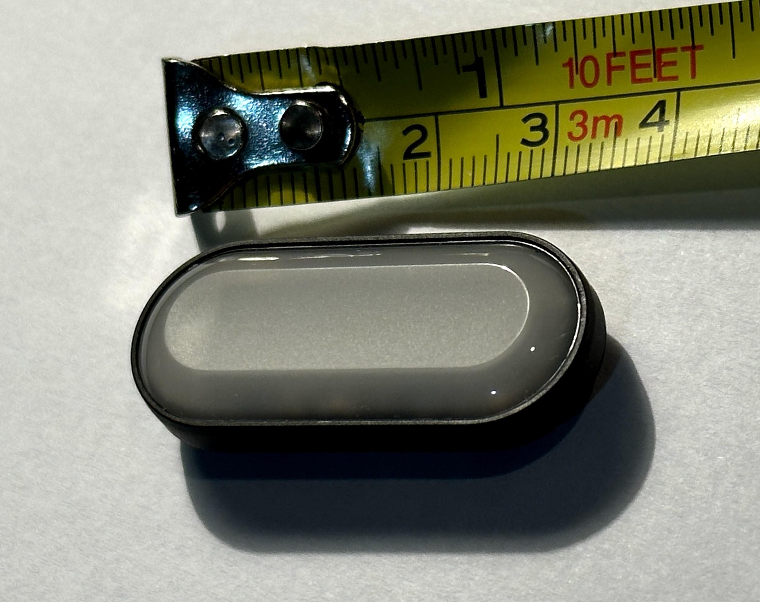
Click to zoom
Application Details
- Equipment Class
- DTS - Digital Transmission System
- Date of Grant
- Jul 31, 2023
- Application Purpose
- Original Equipment
- Date of Application
- Jul 31, 2023
- Equipment Note
- Wearable UV Tracker
- Frequency Range
- 2402.00000000 - 2480.00000000
- Company
- Ink-U-Beta AG
- Country
- Switzerland
Documents & Files
Document Text
Text extracted from the exhibit documents filed with the FCC. Open a document above to read the original.
Users Manual
Ensure the tracker has unobstructed exposure to sunlight. Recommended placements: • Clip onto a thin shirt collar. • Attach to provided wristband. Wearing the Tracker Attaching the clip adapter Quickstart Guide Download the sun-a-wear app from the iOS App Store or Google Play Store (scan the QR code or search for sun-a-wear). Position the tracker in direct sunlight and follow the app’s guided steps for setup. App Setup Please Note: This product is not a medical device. It's not meant for medical prevention, diagnosis, or treatment of any diseases. Use this product responsibly and consult a medical professional for personalized health guidance. Need help? [email protected] • Avoid clipping on materials thicker than 2mm to prevent clip breakage. • Make sure the tracker is not covered by sleeves, hair, or other obstructions. • Avoid placement in areas where collision or contact could cause loss or breakage of the tracker. • Prevent contact with sunscreen or solvents to avoid damage and maintain accuracy. Caution Privacy is important to us: Our app never sends personal information to our servers! See also: https://sun-a-wear.com/en/terms-of-use/ This device complies with Part 15 of the FCC Rules. Operation is subject to the following two conditions: • This device may not cause harmful interference and This device must accept any interference, including interference that may cause undesired operation of the device. FCC Compliance Statement This equipment has been tested and found to comply with the limits for a Class B digital device, pursuant to part 15 of the FCC Rules. These limits are designed to provide reasonable protection against harmful interference in a residential installation. This equipment generates, uses and can radiate radio frequency energy and, if not installed and used in accordance with the instructions, may cause harmful interference to radio communications. Information to User Warning: Failure to heed the following warnings could result in an accident or medical event resulting in death or serious injury. Ink-U-Beta shall not be held responsible for any damages, injuries, or health risks resulting from inaccurate device measurements or user reliance on such measurements. Users assume full responsibility for their decisions and actions related to sun exposure management. • This device must accept any interference, including interference that may cause undesired operation of the device. However, there is no guarantee that interference will not occur in a particular installation. If this equipment does cause harmful interference to radio or television reception, which can be determined by turning the equipment o and on, the user is encouraged to try to correct the interference by one or more of the following measures: • Reorient or relocate the receiving antenna. • Increase the separation between the equipment and receiver. • Connect the equipment into an outlet on a circuit dierent from that to which the receiver is connected. FCC/IC Statement for RF Exposure This device meets the FCC/IC requirements for RF exposure in public or uncontrolled environments. Cet appareil est conforme aux conditions de la FCC/IC en matière de RF dans des environnements publics ou incontrôlée. Changes or modifications not expressly approved by the party responsible for compliance could void the user’s authority to operate the equipment. Warning • Consult the dealer or an experienced radio/TV technician for help. Notice to Users English/French in accordance with current issue of RSS GEN: This device complies with Industry Canada license exempt RSS standard(s). Operation is subject to the following two conditions: 1 this device may not cause interference, and 2 this device must accept any interference, including interference that may cause undesired operation of the device. Canada: Industry Canada (IC) statement Cet appareil est conforme avec Industrie Canada RSS standard exempts de licence (s). Son utilisation est soumise à Les deux conditions suivantes: 1 cet appareil ne peut pas provoquer d’interférences et 2 cet appareil doit accepter Toute interférence, y compris les interférences qui peuvent causer un mauvais fonctionnement du dispositif. Contact: Ink-U-Beta AG Gubelstrasse 7 6300 Zug Switzerland Email: [email protected] Web: https://sun-a-wear.com Product warranty is limited to original defects in material and workmanship. Warranty does not cover collateral damage. Due misuse, abuse, and other inappropriate use of this product are not covered under warranty. This product is not a toy or edible. Warranty Statements HVIN/PMN : SUN02 IC ID: 30629-SUN02 FCC ID: 2BA7X-SUN02 Notice to the User: The FCC/IC ID can also be viewed on your device under: Settings => Help => About the app Avis à l'utilisateur: L'ID de l'FCC/IC peut également être consulté sur votre appareil. Pour voir le contenu: Settings => Help => About the app
External Photos
ExternalPhotos sun-a-wearv2.5.2
ID Label/Location Info
About the App OK sun-a-wear is a registered Trademark of the Swiss company Ink-U-Beta AG. Copyright 2021. All rights reserved. Many thanks go to all those that supported the development of this product. More information at: https://sun-a-wear.com/en/terms-of-use/ FCC ID: 2BA7X-SUN02 app version: 1.14.69 IC ID: 30629-SUN02 Information Security considerations Both regulatory information and dedicated exclusive application are secured and implemented in a factory-set-unalterable format by the manufacturer. The regulatory information can be retrieved and displayed locally, even without an internet connection, and under the control of the end user in possession of the product. The application scales the text size according to the display size, ensuring that the regulatory information is correctly displayed. In addition to the electronic label, the labels, FCC ID, and IC ID are printed in the included user manual. HVIN: SUN02
Internal Photos
InternalPhotos sun-a-wearv2.5.2
Parts List/Tune Up Info
2450 MHz Small SMD Chip AntennaP/N 2450AT42B100 Ground Clearance Requirements Minimized. This antenna was designed for corner or end-mounting Detail Specification: 10/08/13 Page 1 of 4 Inmm No. L ±± 1 W ±± 2 L1 ±± 3 W1 ±± 4 T a ±± Johanson Technology, Inc. reserves the right to make design changes without notice. All sales are subject to Johanson Technology, Inc. terms and conditions. www.johansontechnology.com 4001 Calle Tecate • Camarillo, CA 93012 • TEL 805.389.1166 FAX 805.389.1821 Ver 2.1 2013 Johanson Technology, Inc. All Rights Reserved Note: It is recommended that the designer leave available slots for a "pi" (or shunt-series- shunt) network. The antenna matching network values here are used when antenna is mounted on Johanson's evaluation board. The matching values on clinet's PCB will be different, go to: johansontechnology.com/tuning and see how to obtain the new values. If you need further help, contact our RF Applications Eng Team at: www.johansontechnology.com/en/ask-a-technical-question.html We peform layout review as well as antenna tuning and characterization services. Go to page 2 for details. General Specifications -40 to +85°C 2W max. (CW) 2,000 50 Ω 9.5 dB min. -1.5 dBi typ. (XZ-V) 0 dBi typ. (XZ-V) 2400 - 2500 Mhz 0.0200.0120.500.30 0.0792.00+.004/-.008+0.1/-0.2 0.0080.20 0.50 0.0080.20 2.600.20 +5 ~ +35 °C,Humidity 45~75%RH -40 to +85°C "High Frequency Ceramic Solutions" 0.20 2.00 0.020 0.1020.008 0.008 0.197 0.079 5.00 NC NC NC 2450AT42B100 Mounting Considerations Part Number Frequency Range Peak Gain Average Gain Return Loss Impedance Reel Quanity Power Capacity Function Mechanical DimensionsTerminal Configuration Feeding Point Operating Temperature Recommended Storage Condition Storage Period a T W1 L1 W L 2.810.71 1 0.7 1.0 3 0.7 0.8 2 0.7 1 22 8 3.8 6 3.3 nH 1.5 nH Line width should be designed to match 50Ωcharacteristic impedance (Grounded Co‐Planar Waveguide), depending on PCB material and thickness. (The matching circuit and component values will be different on clients PCB layout, se notes below and go to page 2 for details). Top View Bottom View Side View Yellow area=Ground/Metal Clearance. The "0.82mm" dimmension is a min. requirement, if the designer can make this larger, the better radiation and gain will occur (i.e. 2.0 or 4.0mm) RF Via"stich" around antenna clearance and feed trace for best radiation 2450 MHz Small SMD Chip AntennaP/N 2450AT42B100 Detail Specification: 10/08/13 Page 2 of 4 Test Board: P/N: 2450AT42B100-EB1SMA (orderable item) To order, go to: www. johansontechnology.com/samplerequest Johanson Technology, Inc. reserves the right to make design changes without notice. All sales are subject to Johanson Technology, Inc. terms and conditions. www.johansontechnology.com 4001 Calle Tecate • Camarillo, CA 93012 • TEL 805.389.1166 FAX 805.389.1821 Ver 2.1 2013 Johanson Technology, Inc. All Rights Reserved Typical Electrical Characteristics (T=25 o C) We offer antenna layout review, tuning, and characterization services, go to: www.johansontechnology.com/ipcantennaservices for details and instructions Johanson Evaluation Board (orderable item) "High Frequency Ceramic Solutions" 3.86 40 20 8 (Units in mm) Return Loss (with matching) This 50ΩFeedline can be as short as needed, this lenth is just for reference to our EVB 2450 MHz Small SMD Chip AntennaP/N 2450AT42B100 Detail Specification: 10/08/13 Page 3 of 4 Johanson Technology, Inc. reserves the right to make design changes without notice. All sales are subject to Johanson Technology, Inc. terms and conditions. www.johansontechnology.com 4001 Calle Tecate • Camarillo, CA 93012 • TEL 805.389.1166 FAX 805.389.1821 Ver 2.1 2013 Johanson Technology, Inc. All Rights Reserved Typical Electrical Characteristics (T=25 o C) Radiation Patterns "High Frequency Ceramic Solutions" XY-V/XY-H 180 o 270 o 0 o 90 o X Z Y XY-cut scanning directio n XZ-V/XZ-H 180 o 270 o 0 o 90 o X Z Y XZ-cut scanning directio n YZ-V/YZ- H 180 o 270 o 0 o 90 o X Z Y YZ-cut scanning directio n XY cut @2.45GHz Vertical Horizontal XZ cut @2.45GHz Vertical Horizontal YZ cut @2.45GHz Vertical Horizontal 2450 MHz Small SMD Chip AntennaP/N 2450AT42B100 Detail Specification: 10/08/13 Page 4 of 4 Johanson Technology, Inc. reserves the right to make design changes without notice. All sales are subject to Johanson Technology, Inc. terms and conditions. www.johansontechnology.com 4001 Calle Tecate • Camarillo, CA 93012 • TEL 805.389.1166 FAX 805.389.1821 Ver 2.1 2013 Johanson Technology, Inc. All Rights Reserved www.johansontechnology.com/technical-notes/rohs-compliance.html RoHS Compliance MSL Info www.johansontechnology.com/technical-notes/msl-rating.html www.johansontechnology.com/ipcantennaservices "High Frequency Ceramic Solutions" Part Number Explanation P/N Suffix Packing Style Bulk (loose pieces)Suffix = Seg.2450AT42B100S T & RSuffix = Eeg. 2450AT42B100E Temperature:+5C to +35°CShelf Life: 18 months max. T & R (Reverse)Suffix = Reg. 2450AT42B100R (MOQ Applies) 100% TinSuffix = None eg. 2450AT42B100(S, E, R) Eval Board (1-port SMA antenna test boards) 2450AT42B100-EB1SMA (Page 2) More Details www.johansontechnology.com/ipc-pn-explained Storage Conditions and Shelf Life (On T&R or Bulk) Relative Humidity: 45 to 75% Packaging information Soldering Information Antenna layout and tuning techniques www.johansontechnology.com/ipcsoldering-profile www.johansontechnology.com/ipcpackaging.html Antenna layout review, tuning, and characterization services www.johansontechnology.com/tuning
RF Exposure Info
P2340013_FCC MPE_REV 2.0 Template Revision History Revision Date Revised By Reason for Revision Rev 1.0 5/20/11 SMS Retype into MS2010 and inserted GM links Rev 2.0 12/9/13 MSE Added section for Test Setup Photos, changed address of new building on title page, changed FCC & IC site registration # Rev 3.0 3/3/2014 JE Add minimum safe distance provision. Correct SAR exemption calculation to match latest revision of KDB 447498. 4.0 7/21/15 AR Updated formatting issues throughout report 5.0 9/29/15 AR 6.0 10/13/17 AReed Added statement to report regarding max output power 7.0 9/7/18 AReed Corrected GM fields & general formatting issues 1) ITEMS IN RED THROUGOUT THE REPORT ARE ITEMS THAT NEED TO BE ADDRESSED BY THE ENG AT THE TIME OF COMPLETION. p2340013_FCC_Part 1.1310_Rev 2.0 Page 1 of 4 Test Report Prepared for: Ink-U-Beta AG Model: SUN02 Description: Wearable UV Tracker Serial Number: N/A FCC ID: 2BA7X-SUN02 To FCC Part 1.1310 Date of Issue: June 23, 2023 On the behalf of the applicant: Ink-U-Beta AG Gubelstrasse 7 Zug, ZUG, 6300 Switzerland Attention of: Samuel Welten Ph: +41787617929 E-mail: [email protected] Prepared By Compliance Testing, LLC 1724 S. Nevada Way Mesa, AZ 85204 (480) 926-3100 phone / (480) 926-3598 fax www.compliancetesting.com Project No: p2340013 John Michalowicz Project Test Engineer Reviewed By This report may not be reproduced, except in full, without written permission from Compliance Testing All results contained herein relate only to the sample tested p2340013_FCC_Part 1.1310_Rev 2.0 Page 2 of 4 Test Report Revision History Revision Date Revised By Reason for Revision 1.0 6/22/23 John Michalowicz Original Document 2.0 7/12/23 John Michalowicz Updated test distance to 5mm p2340013_FCC_Part 1.1310_Rev 2.0 Page 3 of 4 ANAB Compliance Testing, LLC, has been accredited in accordance with the recognized International Standard ISO/IEC 17025:2017. This accreditation demonstrates technical competence for a defined scope and the operation of a laboratory quality management system (refer to the joint ISO-ILAC-IAF Communiqué dated January 2009). The tests results contained within this test report all fall within our scope of accreditation, unless noted below. Please refer to http://www.compliancetesting.com/labscope.html for current scope of accreditation. FCC Site Reg. #349717 IC Site Reg. #2044A-2 Non-accredited tests contained in this report: N/A EUT Description Model: SUN02 Description: Wearable UV Tracker Firmware: N/A Software: N/A Serial Number: N/A Additional Information: The EUT is a wearable UV tracker which communicates data wirelessly to a user’s personal device via BLE 2.4 GHz technology. p2340013_FCC_Part 1.1310_Rev 2.0 Page 4 of 4 MPE Evaluation This is a portable device used in Uncontrolled Exposure environment. Limits Uncontrolled Exposure 47 CFR 1.1310 Table 1, (B) 0.3-1.234 MHz: Limit [mW/cm²] = 100 1.34-30 MHz: Limit [mW/cm²] = (180/f²) 30-300 MHz: Limit [mW/cm²] = 0.2 300-1500 MHz: Limit [mW/cm²] = f/1500 1500-100,000 MHz Limit [mW/cm²] = 1.0 Test Data Test Frequency, MHz 2402 Power, EIRP, mW (P) 4.81 Antenna Type chip Distance (R) 5 mm Per KDB This is for calculating a SAR exclusion per KDB 447498. 1) The 1-g and 10-g SAR test exclusion thresholds for 100 MHz to 6 GHz at test separation distances ≤ 50 mm are determined by: [(max. power of channel, including tune-up tolerance, mW)/(min. test separation distance, mm)] · [√f (GHz)] ≤ 3.0 for 1-g SAR and ≤ 7.5 for 10-g extremity SAR, 25 where • f (GHz) is the RF channel transmit frequency in GHz • Power and distance are rounded to the nearest mW and mm before calculation 26 • The result is rounded to one decimal place for comparison • 3.0 and 7.5 are referred to as the numeric thresholds in the step 2 below [(3.03)/(5mm)] [1.55] 0.606 * 1.55 = 0.939 The test exclusions are applicable only when the minimum test separation distance is ≤ 50 mm and for transmission frequencies between 100 MHz and 6 GHz. When the minimum test separation distance is < 5 mm, a distance of 5 mm according to 5) in section 4.1 is applied to determine SAR test exclusion. 0.939 < 3.0 The EUT is compliant with KDB 447498 END OF TEST REPORT
Test Report
P2340013_FCC_Part 15.247_Rev 3.0 Page 1 of 34 Test Report Prepared for: Ink-U-Beta AG Model: SUN02 Description: Wearable UV Tracker Serial Number: N/A FCC ID: 2BA7X-SUN02 IC: 30629-SUN02 To FCC Part 15.247 And IC RSS-247 Date of Issue: June 23, 2023 On the behalf of the applicant: Ink-U-Beta AG Gubelstrasse 7 Zug, ZUG, 6300 Switzerland Attention of: Samuel Welten Ph: +41787617929 E-mail: [email protected] Prepared By Compliance Testing, LLC 1724 S. Nevada Way Mesa, AZ 85204 (480) 926-3100 phone / (480) 926-3598 fax www.compliancetesting.com Project No: p2340013 Test Result: PASS John Michalowicz Project Test Engineer Reviewed By This report may not be reproduced, except in full, without written permission from Compliance Testing. All results contained herein relate only to the sample tested. P2340013_FCC_Part 15.247_Rev 3.0 Page 2 of 34 Test Summary FCC 15.247 Specification RSS-247 Specification Test Name Pass, Fail, N/A Comments 15.247(b) Section 5.4(d) Output Power Pass 15.247(d) Section 5.5 Conducted Spurious Emissions N/A EUT does not have a conducted port 15.247(d), 15.209(a), 15.205 Section 5.5 Radiated Spurious Emissions Pass 15.247(d), 15.209(a), 15.205 Section 5.5 Emissions At Band Edges Pass 15.247(a)(2) Sections 5.2(a) Occupied Bandwidth Pass 15.247(e) Section 5.2(b) Transmitter Power Spectral Density Pass 15.207 RSS-GEN Section 8.8 A/C Powerline Conducted Emissions N/A EUT is a solar powered device Statements of conformity are reported as: • Pass - the measured value is below the acceptance limit, acceptance limit = test limit. • Fail - the measured value is above the acceptance limit, acceptance limit = test limit. References Description CFR47, Part 15, Subpart B Unintentional Radiators CFR47, Part 15, Subpart C Intentional Radiators ANSI C63.10-2013 American National standard for testing Unlicensed Wireless Devices ANSI C63.4-2014 Method and Measurements of Radio-Noise Emissions from low-Voltage Electrical and Electronic Equipment in the range 9kHz to 40GHz. ISO/IEC 17025:2005 General requirements for the Competence of Testing and Calibrations Laboratories KDB 558074 D01 v04 Guidance for Performing Compliance Measurements on Digital Transmission Systems (DTS) Operating under §15.247 P2340013_FCC_Part 15.247_Rev 3.0 Page 3 of 34 Test Report Revision History Revision Date Revised By Reason for Revision 1.0 6/22/23 John Michalowicz Original Document 2.0 7/12/23 John Michalowicz Updated page 7 to show 100% duty cycle Updated output power to show conducted output power Added worst case spurious emission to page 10 3.0 7/321/23 John Michalowicz Added plots for Power P2340013_FCC_Part 15.247_Rev 3.0 Page 4 of 34 Table of Contents Description Page Standard Test Conditions Engineering Practices ............................................................................... 7 Output Power ...................................................................................................................................... 9 Radiated Spurious Emissions ........................................................................................................... 11 Emissions at Band Edges ................................................................................................................. 24 DTS Bandwidth ................................................................................................................................. 26 Transmitter Power Spectral Density (PSD) ....................................................................................... 30 Test Equipment Utilized .................................................................................................................... 33 P2340013_FCC_Part 15.247_Rev 3.0 Page 5 of 34 ANAB Compliance Testing, LLC, has been accredited in accordance with the recognized International Standard ISO/IEC 17025:2017. This accreditation demonstrates technical competence for a defined scope and the operation of a laboratory quality management system (refer to the joint ISO-ILAC-IAF Communiqué dated January 2009). The tests results contained within this test report all fall within our scope of accreditation. Please refer to http://www.compliancetesting.com/labscope.html for current scope of accreditation. FCC Site Reg. #349717 IC Site Reg. #2044A-2 P2340013_FCC_Part 15.247_Rev 3.0 Page 6 of 34 The applicant has been cautioned as to the following 15.21 - Information to User The user’s manual or instruction manual for an intentional radiator shall caution the user that changes or modifications not expressly approved by the party responsible for compliance could void the user’s authority to operate the equipment. 15.27(a) - Special Accessories Equipment marked to a consumer must be capable of complying with the necessary regulations in the configuration in which the equipment is marketed. Where special accessories, such as shielded cables and/or special connectors are required to enable an unintentional or intentional radiator to comply with the emission limits in this part, the equipment must be marketed with, i.e. shipped and sold with, those special accessories. However, in lieu of shipping or packaging the special accessories with the unintentional or intentional radiator, the responsible party may employ other methods of ensuring that the special accessories are provided to the consumer without an additional charge. Information detailing any alternative method used to supply the special accessories for a grant of equipment authorization or retained in the verification records, as appropriate. The party responsible for the equipment, as detailed in § 2.909 of this chapter, shall ensure that these special accessories are provided with the equipment. The instruction manual for such devices shall include appropriate instructions on the first page of text concerned with the installation of the device that these special accessories must be used with the device. It is the responsibility of the user to use the needed…
Text truncated - open the document above for the full version.
Test Setup Photos
Test Setup Photos FCC ID: 2BA7X-SUN02 IC: 30629-SUN02 Test Setup Photos FCC ID: 2BA7X-SUN02 IC: 30629-SUN02
Contact Information
Applicant
Samuel Welten(CTO)
Technical Contact
Non-Technical Contact
Ink-U-Beta AGAlexander Kraft
[email protected]3015291653
Test Firm
Compliance Testing, LLCMichael Schafer
[email protected]480-926-3100
Technical Specifications
| # | Rule Parts | Frequency Range | Power Output |
|---|---|---|---|
| 1 | 15C | 2.40 GHz - 2.48 GHz | 3.00 mW |