2BA8R-TD1N66R1Traffic Enforcement Radar
Sensys Gatso Sweden AB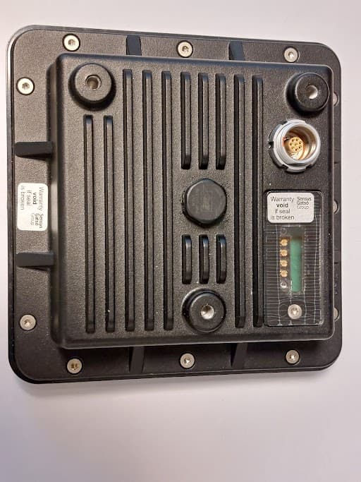
Click to zoom
Application Details
- Equipment Class
- FDS - Part 15 Field Disturbance Sensor
- Date of Grant
- Jun 27, 2023
- Application Purpose
- Original Equipment
- Date of Application
- Jun 27, 2023
- Equipment Note
- Traffic Enforcement Radar
- Frequency Range
- 24089.00000000 - 24170.00000000
- Company
- Sensys Gatso Sweden AB
- Country
- Sweden
Documents & Files
Document Text
Text extracted from the exhibit documents filed with the FCC. Open a document above to read the original.
Users Manual
UM-230609 U SER M ANUAL TD1 Version: V1.1.0 Date: 2023-06-19 Status: Final D ISCLAIMER Copyright © 2023 – Sensys Gatso Group This document and any information enclosed within this document, contains restricted and/or privileged information and is intended only for authorised screening and/or confidential presentation at the discretion of Sensys Gatso Group. If you are not the intended observer of this document, you must not disseminate, modify, copy/plagiarise or take action in reliance upon it, unless permitted by the Sensys Gatso Group. None of the materials provided on this document may be used, reproduced or transmitted in any form or by any means, electronic or mechanical, including recording or the use of any information storage and retrieval system, without written permission from Sensys Gatso Group. If you received this document in error please notify Sensys Gatso Group immediately. The confidential nature of and/or privilege in the document enclosed is not waived or lost as a result of a mistake or error in this document. Sensys Gatso Group is in no event liable for loss or damage including without limitations of indirect or consequential loss or damage whatsoever, whether it was caused by: 1. accessing or other related actions to this document 2. or any other actions other than stated in this document Sensys Gatso Group assumes that all readers understand risks involved within this document and/or its attached materials. All rights reserved. Compiled by Sensys Gatso Group. Please contact [email protected] for more information. Translation disclaimer Any translations of this document will be done with the utmost care. However, Sensys Gatso Group does not accept any liability for the correctness and completeness of the compilation and content of this translation and the direct or indirect consequences of acting or failing to act based on this translation. It is not possible to derive any rights, of whatever nature, from the compilation and contents of the translations. In all cases, the original document shall be decisive. UM-230609 User manual - TD1 1 / 11 Regulations, Standards & Guidelines CE Sensys Gatso declares that this product is manufactured in conformity with the essential requirements in the applicable directives, and that the relevant information conformity assessment procedures have been fulfilled. ISO Sensys Gatso’s Management System is certified for ISO 9001 Quality management system, ISO 14001 Environmental management system and ISO 27001 Information technology – Security techniques. RoHS & WEEE Sensys Gatso follows the RoHS II 2011/65/EU (Restriction of Hazardous Substances) and WEEE 2012/19/EU (Waste Electrical and Electronic Equipment) directives. WELMEC 7.2 Measuring Instruments Directive 2004/22/EC. Safety instructions This manual holds information and instructions for the correct and efficient use of the TD1. Following these instructions avoids hazardous situations, damage to the system, or a malfunction of the system. Scope This manual holds information and instructions for the correct and efficient use of the TD1. Some of the items described in this document are optional and may therefore not be available in all systems. Please contact Sensys Gatso Group for details. All images, drawings and print screens shown in this manual are indicative and can differ from the originals, due to recent adaptations to hardware or software by Sensys Gatso. Target audience This document is intended for users that have been trained to work with the system and are familiar with its lawful use. In addition, the user must have basic skills in working with computers and setting up network connections. Reader liability This manual shall be carefully read and understood by any user operating the system. If there are any questions regarding the contents of this document or the proper use of the system, please contact Sensys Gatso or its distributor. Contact details are listed on the last page of this document. UM-230609 User manual - TD1 2 / 11 FCC DECLARATIONS Compliance statement (part 15.19) This device complies with part 15 of the FCC Rules. Operation is subject to the following two conditions: 1) this device may not cause harmful interference, and 2) this device must accept any interference received, including interference that may cause undesired operation. Warning (part 15.21) Changes or modifications not expressly approved by the party responsible for compliance could void the user’s authority to operate the equipment. RF Exposure (OET Bulletin 65) To comply with FCC RF exposure requirements for mobile transmitting devices, this transmitter should only be used or installed at locations where there is at least 20cm separation distance between the antenna and all persons. Information to the User (Part 15.105 (a)) This equipment has been tested and found to comply with the limits for a Class A digital device, pursuant to part 15 of the FCC Rules. These limits are designed to provide reasonable protection against harmful interference when the equipment is operated in a commercial environment. This equipment generates, uses, and can radiate radio frequency energy and, if not installed and used in accordance with the instruction manual, may cause harmful interference to radio communications. Operation of this equipment in a residential area is likely to cause harmful interference in which case the user will be required to correct the interference at his own expense. UM-230609 User manual - TD1 3 / 11 Used symbols Text with an exclamation mark in a red triangle means: Please read the information carefully and/or carry out the given instructions precisely. Ignoring this warning may cause personal injury, cause damage to the system, or produce false data. Text with an i mark in a green circle means: Please read this information to not only use the system accurately and safely, but also efficiently. Precautions RF radiations The radar used does not pose a serious threat or cause …
Text truncated - open the document above for the full version.
Attestation Statements
Antenna Information for Unlicensed Devices Date: June20, 2023 American Certification Body, Inc. 313 Park Avenue Suite 300 Falls Church, VA 22046 To Whom It May Concern: Only radiatedmeasurements are used to show compliance with FCC limits for fundamental and spurious emissions. Thank you, By:__________________________Patrick Chiocchio (Signature)(Print name) Title:Quality Assurance Engineer On behalf of:Sensys Gatso Sweden AB (Company Name) Telephone:+46 73-59 77 658
External Photos
TD1 17-012166 External photos TD1 front DED-230619 TD1 17-012166 External photos v1.0.0 1 TD1 backsid e DED-230619 TD1 17-012166 External photos v1.0.0 2 TD1 top TD1 bottom DED-230619 TD1 17-012166 External photos v1.0.0 3 TD1 right TD1 left DED-230619 TD1 17-012166 External photos v1.0.0 4 DED-230619 TD1 17-012166 External photos v1.0.0 5
ID Label/Location Info
ID L ABEL The product ID is made of resistant material, specialized ultrabond permanent acrylic adhesive (ASTM D903). The product ID is permanently attached to/not removable from the device. The operating temperature for this material is between -30°C to +80°C and light proofness DIN 53388. DED-230601 TD1 ID Label and Location v1.0.0 SGG © 2023 page 3 of 5 L OCATION TD1 FCC ID label: DED-230601 TD1 ID Label and Location v1.0.0 SGG © 2023 page 4 of 5 Radar with mounted bracket. DED-230601 TD1 ID Label and Location v1.0.0 SGG © 2023 page 5 of 5
Internal Photos
TD1 17-012166 Internal photos TD1 front no radome DED-230619 TD1 17-012166 internal photos v1.0.0 1 TD1 without front end DED-230619 TD1 17-012166 internal photos v1.0.0 2 11-0762 C and 11-0710 E 11-0762 C mount DED-230619 TD1 17-012166 internal photos v1.0.0 3 11-0762 C front 11-0762 C back 11-0710 E front mount DED-230619 TD1 17-012166 internal photos v1.0.0 4 11-0710 E back DED-230619 TD1 17-012166 internal photos v1.0.0 5 11-0710 E front DED-230619 TD1 17-012166 internal photos v1.0.0 6 11-0755 E front DED-230619 TD1 17-012166 internal photos v1.0.0 7 11-0755 E back DED-230619 TD1 17-012166 internal photos v1.0.0 8 11-0755 E back no cover DED-230619 TD1 17-012166 internal photos v1.0.0 9
RF Exposure Info
Rhein Tech Laboratories, Inc. Client: Sensys Gatso Sweden AB 360 Herndon Parkway Model: 17-012166 TD1 Suite 1400 Standard: FCC Part 15.245 Herndon, VA 20170 (USA) Report #: 2022098 Page 17 of 25 Appendix A: RF Exposure FCC Rules and Regulations Part 1.1307, 1.1310, 2.1091, 2.1093 1 General Information Environment: General Population/Uncontrolled Exposure Device category: Disturbance sensor Modulation Type/Mode: FMCW 2 Antenna Operating Configuration and Test Conditions FCC 15.245 Antenna Simulated Antenna Gain (dBi) Integrated Patch Array 11 Note: Simulated gain presented but not used in calculations below. Instead, worst-case EIRP used for RF Exposure calculations below. Antenna Type Highest Peak Measured EIRP Power (dBuV/m) Highest Peak Measured EIRP Power (dBm) Highest Peak Measured EIRP Power (mW) Integrated Patch Array Antenna 119.8 24.6 288.4 3 MPE Calculation The maximum distance from the antenna at which MPE is met or exceeded d, in centimeters, is calculated from the power density S, in mW/cm^2, transmit power P in mW, and the transmit antenna numeric gain G. The limit for general population/uncontrolled exposure from 1500-100000 MHz is 1 mW/cm 2 . S = EIRP (mW)/(4*PI*d^2) d = SQRT ((EIRP (mw)/S*4PI) where: S = Power density (mW/cm 2 ); EIRP = Effective Isotropic Radiated Power (mW); d = distance Below is the MPE Calculation for the EUT and its integrated patch array antenna using the 1 mW/cm 2 power density limit for general population/uncontrolled exposure, and the worst-case measured peak EIRP of 288.4 mW and solving for distance (d) in (cm) and solving for the worst-case power density at 20 cm worst-case mobile distance is as follows: Linear Log Duty % = 100 0 dB Worst-case measured peak EIRP = 288.4 mW 24.6 dBm d = 4.8 cm S (20cm) = 0.0574045 mW/cm^2
Test Report
Engineering Solutions & Electromagnetic Compatibility Services 360 Herndon Pkwy | Suite 1400 | Herndon | Virginia 20170 | USA Phone: 703.689.0368 | Fax: 703.689.2056 | www.rheintech.com FCC 15.245 Test Report Test Lab: Rhein Tech Laboratories, Inc. Tel: 703-689-0368 360 Herndon Parkway Fax: 703-689-2056 Suite 1400 www.rheintech.com Herndon, VA 20170 (USA) Applicant: Sensys Gatso Sweden AB Tel: +46 36 34 29 80 Vasavagen 3C Box 2174 SE-554 54 Jonkoping Sweden Model 17-012166 TD1 Test Report Date June 27, 2023 FCC ID 2BA8R-TD1N66R1 RTL Work Order # 2022098 RTL Quote QRTL22-098B American National Standard Institute ANSI C63.10-201 3: American National Standard of Procedures for Compliance Testing of Unlicensed Wireless Devices FCC Classification FDS: Field Disturbance Sensor FCC Rule Part(s)/ Guidance FCC 15.245: O peration within the bands 902–928 MHz, 2435–2465 MHz, 5785–5815 MHz, 10500-10550 MHz, and 24075–24175 GHz (10-01-21) Frequency Range (MHz) Output Power (W) Frequency Tolerance (%) Emission Designator 24075–24175 N/A N/A N/A I, the undersigned, hereby declare that the equipment tested and referenced in this report conforms to the identified standard(s) as described in this test report. No modifications were made to the equipment during testing in order to achieve compliance with these standards. Furthermore, there was no deviations from, additions to, or exclusions from, the applicable parts of ANSI 63.10, FCC Part 2 and Part 15. Signature: Date: June 27, 2023 Name: Desmond A. Fraser Position: President This report may not be reproduced, except in full, without the written approval of Rhein Tech Laboratories, Inc. and Sensys Gatso Sweden AB. The test results relate only to the item(s) tested. This replaces R1.0. These test(s) are accredited under Rhein Tech Laboratories, Inc. ISO/IEC 17025 accreditation issued by ANAB. Refer to certificate and scope of accreditation AT-1445. Rhein Tech Laboratories, Inc. Client: Sensys Gatso Sweden AB 360 Herndon Parkway Model: 17-012166 TD1 Suite 1400 Standard: FCC Part 15.245 Herndon, VA 20170 (USA) Report #: 2022098 Page 2 of 26 Table of Contents 1 General Information ............................................................................................................................... 4 1.1 Scope ............................................................................................................................................... 4 1.2 Description of EUT ........................................................................................................................... 4 1.3 Test Facility ...................................................................................................................................... 4 1.4 Related Submittal(s)/ Grant(s) ......................................................................................................... 4 1.5 Modification(s) to EUT ...................................................................................................................... 4 1.6 Deviation(s) from Standard(s) .......................................................................................................... 4 1.7 Acronyms Used in this Document .................................................................................................... 4 2 Test Information ..................................................................................................................................... 5 2.1 Exercising the EUT .......................................................................................................................... 5 2.2 Description of Test Mode(s) ............................................................................................................. 5 2.3 Test Result Summary ....................................................................................................................... 5 2.4 Test System Details ......................................................................................................................... 5 2.5 Test Configuration ............................................................................................................................ 6 3 Conducted Emissions – FCC Part 15.207 ............................................................................................. 7 3.1 Conducted Emissions Test Procedure ............................................................................................. 7 3.2 Conducted Emissions Limits ............................................................................................................ 7 3.3 Measurement Uncertainty ................................................................................................................ 7 3.4 Conducted Emissions Test Data ...................................................................................................... 7 4 Radiated Emissions – FCC Part 15.209, 15.245(b) ............................................................................ 10 4.1 Radiated Emissions Test Procedure .............................................................................................. 10 4.2 Radiated Emissions Limits ............................................................................................................. 10 4.3 Measurement Uncertainty .............................................................................................................. 11 4.4 Radiated Emissions Test Data ....................................................................................................... 11 5 20 dB Bandwidth – FCC 15.215(c) ...................................................................................................... 15 5.1 20 dB Bandwidth Test Procedure .................................................................................................. 15 5.2 Measurement Uncertainty ............................................................................................................…
Text truncated - open the document above for the full version.
Test Setup Photos
Rhein Tech Laboratories, Inc. Client: Sensys Gatso Sweden AB 360 Herndon Parkway Model: 17-012166 TD1 Suite 1400 Standard: FCC Part 15.245 Herndon, VA 20170 (USA) Report #: 2022098 Page 18 of 25 Appendix B: Test Photographs Photograph 1: Radiated Emissions – Front (Less than 1 GHz) Rhein Tech Laboratories, Inc. Client: Sensys Gatso Sweden AB 360 Herndon Parkway Model: 17-012166 TD1 Suite 1400 Standard: FCC Part 15.245 Herndon, VA 20170 (USA) Report #: 2022098 Page 19 of 25 Photograph 2: Radiated Emissions – Back (Less than 1 GHz) Rhein Tech Laboratories, Inc. Client: Sensys Gatso Sweden AB 360 Herndon Parkway Model: 17-012166 TD1 Suite 1400 Standard: FCC Part 15.245 Herndon, VA 20170 (USA) Report #: 2022098 Page 20 of 25 Photograph 3: Radiated Emissions – Front (Greater than 1 GHz) Rhein Tech Laboratories, Inc. Client: Sensys Gatso Sweden AB 360 Herndon Parkway Model: 17-012166 TD1 Suite 1400 Standard: FCC Part 15.245 Herndon, VA 20170 (USA) Report #: 2022098 Page 21 of 25 Photograph 4: Radiated Emissions – Back (Greater than 1 GHz) Rhein Tech Laboratories, Inc. Client: Sensys Gatso Sweden AB 360 Herndon Parkway Model: 17-012166 TD1 Suite 1400 Standard: FCC Part 15.245 Herndon, VA 20170 (USA) Report #: 2022098 Page 22 of 25 Photograph 5: Radiated Emissions – Front (Greater than 1 GHz) Radar Measurements Rhein Tech Laboratories, Inc. Client: Sensys Gatso Sweden AB 360 Herndon Parkway Model: 17-012166 TD1 Suite 1400 Standard: FCC Part 15.245 Herndon, VA 20170 (USA) Report #: 2022098 Page 23 of 25 Photograph 6: Conducted Emissions (Front) Rhein Tech Laboratories, Inc. Client: Sensys Gatso Sweden AB 360 Herndon Parkway Model: 17-012166 TD1 Suite 1400 Standard: FCC Part 15.245 Herndon, VA 20170 (USA) Report #: 2022098 Page 24 of 25 Photograph 7: Conducted Emissions (Back) Rhein Tech Laboratories, Inc. Client: Sensys Gatso Sweden AB 360 Herndon Parkway Model: 17-012166 TD1 Suite 1400 Standard: FCC Part 15.245 Herndon, VA 20170 (USA) Report #: 2022098 Page 25 of 25 Photograph 8: Telecom Emissions
Contact Information
Applicant
Patrick Chiocchio
Technical Contact
Rhein Tech Laboratories, Inc.Desmond Fraser
360 Herndon Parkway · Herndon, Virginia · United States
Test Firm
Rhein Tech Laboratories, Inc.Richard McMurray
Technical Specifications
| # | Rule Parts | Frequency Range | Power Output |
|---|---|---|---|
| 1 | 15.245 | 24.09 GHz - 24.17 GHz | - |