2BAA9-UCR2Remote Two
Unfolded Circle ApS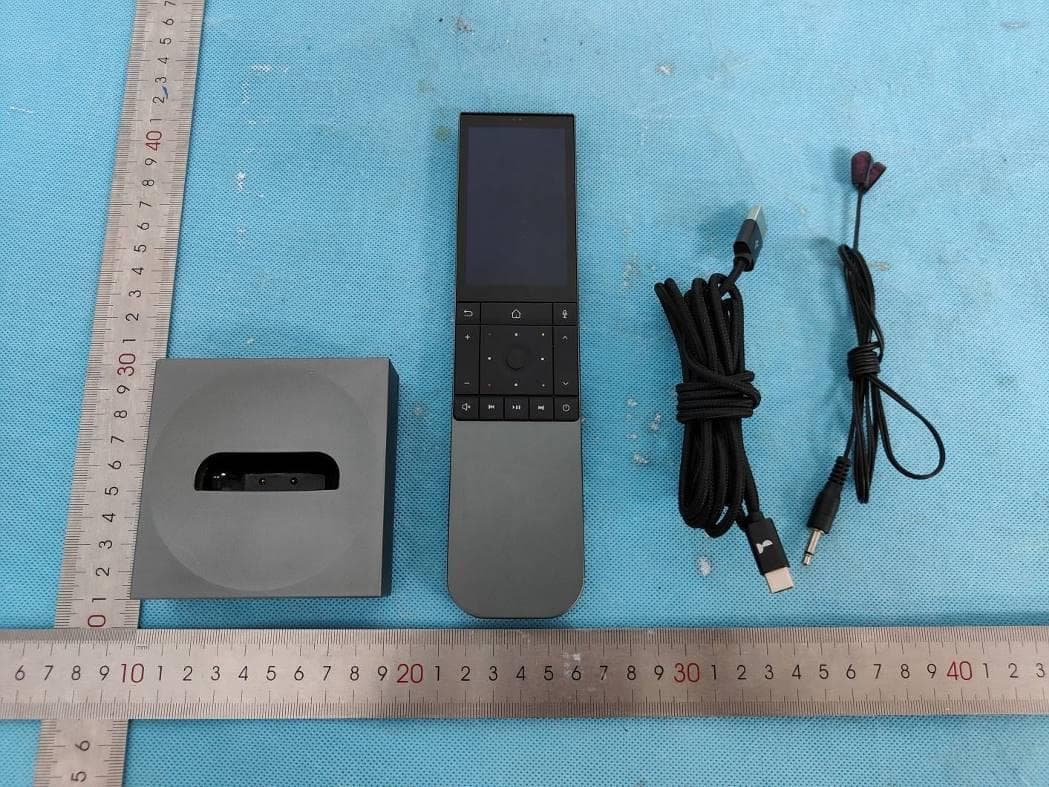
Click to zoom
Application Details
- Equipment Class
- DSS - Part 15 Spread Spectrum Transmitter
- Date of Grant
- Jul 18, 2023
- Application Purpose
- Original Equipment
- Date of Application
- Jul 17, 2023
- Equipment Note
- Remote Two
- Frequency Range
- 2402.00000000 - 2480.00000000
- Company
- Unfolded Circle ApS
- Country
- Denmark
Documents & Files
Document Text
Text extracted from the exhibit documents filed with the FCC. Open a document above to read the original.
Users Manual
Quick Start Guide Remote Two What’s in the box? Initial setup Press and hold for 2 seconds to power on RemoteIR Extender Cable with 2 Emitters USB-C to USB-A Cable Smart Charging Dock Press and hold the Power button for 2 seconds to turn on the remote and follow the instructions on the screen for intial setup. Charging the remote Positioning the dock IR Extenders You can place the extenders inside the cabinet Smart Charging Dock Emits IR signals on the sides and top Position your Smart Charging Dock so it has an unobstructed line of sight to the IR (infrared) devices you want to control. You can use the supplied IR extender to place the emitters inside your cabinet to reach devices behind closed doors. Place the remote in the dock to charge it. Internal magnets will help you guide the remote to the correct position. The status LED on the dock will light up in a breathing pattern to indicate the remote is charging. Only use power supplies that meet the minimum requirements of the Smart Charging Dock. Version 1.02022UCQSG112022 Support For more information and support, please visit unfoldedcircle.com/support Important ATTENTION: ALL INFORMATION IN THIS DOCUMENT CAN CHANGE WITHOUT NOTICE. IMPORTANT: BY USING YOUR UNFOLDED CIRCLE PRODUCT YOU AGREE TO BE BOUND BY THE TERMS AND CONDITIONS. To read these terms, please go to: unfoldedcircle.com/legal or scan the QR code: English Important safety instructions • Read these instructions. • Keep these instructions. • Heed all warnings. • Follow all instructions. • Clean only with dry cloth. Household cleaners or solvents can damage the finish on your components. • Install in accordance with the manufacturer’s instructions. • Do not use this product near water or expose the products to dripping or splashing of any water liquid and do not place objects filled with liquids, such as vases near or on the Unfolded Circle products. • Do not install near any heat sources such as radiators, heat registers, stoves, or other apparatus (including amplifiers) that produce heat. • Only use attachments/accessories and power supplies that meet the requirements specified by the manufacturer. • Refer all servicing to qualified service personnel. Servicing is required when the apparatus has been damaged in any way, such as power-supply cord or plug is damaged, liquid has been spilled or objects have fallen into the apparatus, the apparatus has been exposed to rain or moisture, does not operate normally, or has been dropped. • WARNING: No naked flame sources, such as lighted candles should be placed on the product. • Using USB-C chargers of poor quality may trigger false operations during charging. • The USB-C charger should adhere to EN 62368-1. • The maximum length of an ethernet cable should not exceed 3 m (10 ft). • The product is intended for indoor use in dry, domestic environments only. • The product should only be used in enviroments with ambient temperatures between 5°C to 40°C (41°F to 104°F). • Turn off your device in restricted areas where the use of mobile devices is prohibited. • Always obey rules and regulations when in restricted areas, such as, in aircraft, movie theater, in hospitals or near medical equipment, near gas or fuel, construction sites, blasting sites and other areas. • The device screen is made of glass. If the glass gets broken, stop using the device and do not touch the broken glass parts. • Risk of explosion if a battery is replaced with an incorrect type that can defeat a safeguard (for example, in the case of some lithium battery types) • Do not dispose of a battery into fire or a hot oven, or mechanically crush or cut a battery, because it can result in an explosion. • Do not leave a battery in an extremely high temperature surrounding environment, because it can result in an explosion or the leakage of flammable liquid or gas. • Do not subject a battery to extremely low air pressure because it may result in an explosion or the leakage of flammable liquid or gas. • Do not short-circuit the battery terminals with metal items. Unfolded Circle ApS declares that this product herewith complies with the requirements of the EMC Directive 2014/30/EU, RED Directive 2014/53/EU, RoHS Directive 2011/65/EU when installed and used in accordance with the manufacturer’s instructions. A copy of the full Declaration of Conformity may be found at unfoldedcircle.com/legal/compliance The following standards were used to assess the product: EN 55032: 2015+A1: 2020, EN 55035: 2017+A11: 2020, EN IEC 61000-3-2: 2019+A1: 2021, EN 61000-3-3: 2013+A2: 2021, ETSI EN 301 489-1 V2.2.3: 2019, ETSI EN 301 489-17 V3.2.4: 2020, ETSI EN 300328 V2.2.2: 2019, EN IEC 62311: 2020, EN 50665: 2017, EN IEC 62368-1:2020+A11:2020 Compliance with 2014/53/EU Radio Equipment Directive (RED) In accordance with Article 10.8(a) and 10.8(b) of the RED, the following table provides information on the frequency bands used and the maximum RF transmit power of the product for sale in the EU: Frequency rangeMax. Transmit Power 2412-2472 MHz7.92 dBm 2402-2480 MHz0.05 dBm As a result of electrostatic discharge, the remote(UCR2) may restart and cannot return to the previous user interface state. The user needs to navigate to the previous state. Prolonged listening at high volume levels may cause hearing damage. The symbol means that according to local laws and regulations your product and/or its battery shall be disposed of separately from household waste. When this product reaches its end of life, take it to a collection point designated by local authorities. Hereby, Unfolded Circle ApS declares that the radio equipment Remote Two is in compliance with Radio Equipment Regulations 2017. Full text of UKCA declaration of conformity is available at unfoldedcircle.com/legal/compliance Fcc statement This device complies with Part 15 of FCC Rules. Operation is subject to the following two conditions: (1) this device may not cause harmful interference, and (2) this device must accept any interferenc…
Text truncated - open the document above for the full version.
Attestation Statements
Unfolded Circle ApS Nordre Fasanvej 124A 1TV 2000 Frederiksberg Denmark CVR Nr.: 42589977 VAT Nr.: DK42589977 Phone: +45 88 74 31 96 Email: [email protected] www.unfoldedcircle.com The Commission’s Covered List is published by the Public Safety and Homeland Security Bureau and posted on the Commission’s website. This Covered List, which is periodically updated, identifies particular equipment, produced by particular entities, that constitutes “covered” equipment. https://www.fcc.gov/supplychain/coveredlist Date 28 June 2023 Office of Engineering Technology Federal Communications Commission 7435 Oakland Mills Road Columbia, MD 21046 Attestation Statements The Commission adopted rules that prohibit equipment authorization for “covered” telecommunications equipment and video surveillance equipment produced by entities identified on the Commission’s Covered List, which is periodically updated. See the Covered List for more details. This Attestation Statement is to confirm that we follow the Section 2.911(d)(5)(i)-(ii) Applicant Company name: Unfolded Circle ApS Grantee code: 2BAA9 FCC ID: 2BAA9-UCR2 Contact Name: Lutz Harder Address: Nordre Fasanvej 124A 1TV, 2000 Frederiksberg, Denmark Telephone No: +45 88 74 31 96 Email: [email protected] i. Unfolded Circle ApS (“the applicant”) certifies that the equipment for which authorization is sought is not “covered” equipment prohibited from receiving an equipment authorization pursuant to section 2.903 of the FCC rules. The applicant must sign this certification. ii. Unfolded Circle ApS (“the applicant”) certifies that, as of the date of the filing of the application, the applicant is not (as a specifically named entity or any of its subsidiaries or affiliates) identified on the Covered List as an entity producing “covered” equipment. The applicant must sign this certification. Unfolded Circle ApS (“the applicant”) certifies that, as of the date of the filing of the application, the applicant is not identified on the Covered List as an entity producing “covered” equipment . Lutz Harder Chief Technology Officer
Cover Letter(s)
Unfolded Circle ApS Nordre Fasanvej 124A 1TV 2000 Frederiksberg Denmark CVR Nr.: 42589977 VAT Nr.: DK42589977 Date 28 June 2023 Letter of Authorization Product Name: Remote Two Model Number: UCR2 FCC Identifier: 2BAA9-UCR2 We authorize LGAI Technological Center S.A., Ronda de la Font del Carme, s/n, 08193 Bellaterra, Spain, to act on our behalf on all matters concerning the above named equipment. Any individual within LGAI Technological Center S.A. is authorized to act on our behalf and take action on the application. We declare that authorize LGAI Technological Center S.A., Ronda de la Font del Carme, s/n, 08193 Bellaterra, Spain, is allowed to forward all information related to the approval project to the Federal Communication Commission and to discuss any issues concerning the approval application. Any and all acts carried out by LGAI Technological Center S.A. on our behalf shall have the same effect as acts of our own. Sincerely, Lutz Harder Chief Technology Officer Phone: +45 88 74 31 96 Email: [email protected] www.unfoldedcircle.com
Cover Letter(s)
Unfolded Circle ApS Nordre Fasanvej 124A 1TV 2000 Frederiksberg Denmark CVR Nr.: 42589977 VAT Nr.: DK42589977 Date 28 June 2023 Office of Engineering Technology Federal Communications Commission 7435 Oakland Mills Road Columbia, MD 21046 Request for Confidentiality Confidentiality request for FCC ID: 2BAA9-UCR2, Unfolded Circle Remote Two, UCR2 In accordance with Sections 0.457 (d)(1)(ii) and 0.459 of the FCC Regulations, we request permanent confidentiality for the below indicated exhibits: • Block diagrams • Operational description • Part lists • Schematic diagrams These documents contain information about the product which Unfolded Circle considers proprietary, confidential and would otherwise not release to the general public. Disclosure of this information would benefit Unfolded Circle’s competitors and provide unfair advantage in the market. Short-term confidentiality: We hereby request 180 days [up to 180 days] short-term confidentiality for the following exhibits. This is to avoid premature release of sensitive information prior to marketing or release of the product to the public. • External photos • Test setup photos • User’s manual • Internal photos Please contact me if there are any further questions or information needed. Sincerely, Lutz Harder Chief Technology Officer email: [email protected] Phone: +45 88 74 31 96 Email: [email protected] www.unfoldedcircle.com
External Photos
FCC ID: 2BAA9-UCR2 IC: 30360-UCR2 External photos FCC ID: 2BAA9-UCR2 IC: 30360-UCR2 FCC ID: 2BAA9-UCR2 IC: 30360-UCR2 FCC ID: 2BAA9-UCR2 IC: 30360-UCR2
ID Label/Location Info
Remote Two Label FCC ID: 2BAA9-UCR2 and IC: 30360-UCR2 will be shown in product display as e-label To access the e-label information: Step 1 — Go to settings Step 2 — About Step 3 — Regulatory Remote Two Model nr.: UCR2 FCC ID: 2BAA9-UCR2 IC: 30360-UCR2 Battery: 3.7V 2400mAh Unfolded Circle ApS Nordre Fasanvej 124A 1TV 2000 Frederiksberg Denmark E-Ladel
Internal Photos
FCC ID: 2BAA9-UCR2 IC: 30360-UCR2 Internal photos FCC ID: 2BAA9-UCR2 IC: 30360-UCR2 BT WIFI Chip BT WIFI Antenna FCC ID: 2BAA9-UCR2 IC: 30360-UCR2 FCC ID: 2BAA9-UCR2 IC: 30360-UCR2
RF Exposure Info
FCC SAR Test Report Report Format Version 5.0.0 Issued Date : Jun. 16, 2023 Report No. : W7L-P23060010SA01 FCC SAR Test Report Report No. : W7L-P23060010SA01 Applicant : Unfolded Circle ApS Address : Nordre Fasanvej 124A 1TV 2000 Frederiksberg Denmark Manufacturer : Unfolded Circle ApS Address : Nordre Fasanvej 124A 1TV 2000 Frederiksberg Denmark Product : Remote Two FCC ID : 2BAA9-UCR2 Brand : Unfolded Circle Model No. : UCR2 Standards : FCC 47 CFR Part 2 (2.1093) / IEEE C95.1:1992 / IEEE 1528:2013 KDB 865664 D01 v01r04 / KDB 865664 D02 v01r02 / KDB 248227 D01 v02r02 KDB 447498 D04 v01 Sample Received Date : Jun. 13, 2023 Date of Testing : Jun. 15, 2023 FCC Designation No. : CN1171 FCC Site Registration No. : 525120 CERTIFICATION: The above equipment have been tested by BV 7LAYERS COMMUNICATIONS TECHNOLOGY (SHENZHEN) CO. LTD., and found compliance with the requirement of the above standards. The test record, data evaluation & Equipment Under Test (EUT) configurations represented herein are true and accurate accounts of the measurements of the sample’s SAR characteristics under the conditions specified in this report. It should not be reproduced except in full, without the written approval of our laboratory. The client should not use it to claim product certification, approval, or endorsement by A2LA or any government agencies. Prepared By : Approved By : Jerry Chen / Engineer Luke Lu / Manager This report is governed by, and incorporates by reference, CPS Conditions of Service as posted at the date of issuance of this report at http://www.bureauveritas.com/home/about-us/our-business/cps/about- us/terms-conditions/and is intended for your exclusive use. Any copying or replication of this report to or for any other person or entity, or use of our name or trademark, is permitted only with our prior written permission. This report sets forth our findings solely with respect to the test samples identified herein. The results set forth in this report are not indicative or representative of the quality or characteristics of the lot from which a test sample was taken or any similar or identical product unless specifically and expressly noted. Our report includes all of the tests requested by you and the results thereof based upon the information that you provided to us. Measurement uncertainty is only provided upon request for accredited tests. You have 60 days from date of issuance of this report to notify us of any material error or omission caused by our negligence or if you require measurement uncertainty; provided, however, that such notice shall be in writing and shall specifically address the issue you wish to raise. A failure to raise such issue within the prescribed time shall constitute you unqualified acceptance of the completeness of this report, the tests conducted and the correctness of the report contents. FCC SAR Test Report Report Format Version 5.0.0 Issued Date : Jun. 16, 2023 Report No. : W7L-P23060010SA01 Table of Contents Release Control Record ............................................................................................................................................................... 3 1. Summary of Maximum SAR Value ....................................................................................................................................... 4 2. Description of Equipment Under Test ................................................................................................................................. 5 3. SAR Measurement System ................................................................................................................................................... 6 3.1 Definition of Specific Absorption Rate (SAR) ............................................................................................................... 6 3.2 SPEAG DASY System ................................................................................................................................................. 6 3.2.1 Robot .................................................................................................................................................................. 7 3.2.2 Probes ................................................................................................................................................................ 8 3.2.3 Data Acquisition Electronics (DAE) .................................................................................................................... 8 3.2.4 Phantoms ........................................................................................................................................................... 9 3.2.5 Device Holder ................................................................................................................................................... 10 3.2.6 System Validation Dipoles ................................................................................................................................ 10 3.2.7 Tissue Simulating Liquids ................................................................................................................................. 11 3.3 SAR System Verification ............................................................................................................................................ 13 3.4 SAR Measurement Procedure ................................................................................................................................... 14 3.4.1 Area & Zoom Scan Procedure ......................................................................................................................... 14 3.4.2 Volume Scan Procedure ................................................................................................................................... 14 3.4.3 Power Drift Monitoring .....................................................................................................…
Text truncated - open the document above for the full version.
RF Exposure Info
FCC SAR Test Report Report Format Version 5.0.0 Issued Date : Jun. 16, 2023 Report No. : W7L-P23060010SA01 Appendix D. Photographs of EUT and Setup
Test Report
AEC-Q200 Qualification Available New Global P/N 2450AT18D0100001 Legacy P/N 2450AT18D0100 Detail Specification: Page 1 of 7 Top Bottom ¹Efficiency measured on Johanson's evaluation board PN 2450AT18D0100001CE1 No. ±± 1 ±± 2 ±± 3 4 ±± Function 1: Antenna fed from left Function 2: Antenna fed from right https://www.johansontechnology.com 4001 Calle Tecate • Camarillo, CA 93012 • TEL 805.389.1166 FAX 805.389.1821 Ver. 4.4 2021 Johanson Technology, Inc. All Rights Reserved Frequency (GHz) Peak Gain (dBi) Average Gain (dBi) Radiated Efficiency¹ 2.4 - 2.5 1.5 typ. (XZ-total) -1.0 typ. (XZ-total) 72% Humidity 45 - 75% RH 50 3 max. (CW) -40 to +125°C Recommended Storage Conditions and Period for unused Product on T&R 18 months max. +5 to +35°C Return Loss (dB) Impedance (Ω) Input Power (W) Operating Temperature 10 min. e.g. 2450AT18D0100001B e.g. 2450AT18D0100001E Packing Style T & R 3,000 Reel Quantity (pcs./reel) Bulk (loose pcs.) Part Number Explanation (See last page for more info on new and legacy part numbers) e.g. 2450AT18D0100001(B or S) Suffix = B Suffix = E 100% TinSuffix = None Terminal Configuration FEED GND GND GND GND GND GND FEED Function 1Function 2 b 0.0200.500.20.008 a 0.0120.30+0.1 / -0.2 +0.004 / -0.008 1.200.10.004 2450AT18D0100001CE1 mm Evaluation Board Johanson Technology, Inc. reserves the right to make design changes without notice. All sales are subject to Johanson Technology, Inc. terms and conditions. P/N Suffix Mechanical Dimensions In L 0.1260.0083.200.2 W 0.0630.0081.600.2 T 0.047 High Frequency Ceramic Solutions 8/24/2022 Let us help you with the antenna design, optimization, and tuning! 2450AT18D0100001 2.45 GHz SMD Antenna, EIA 1206, Detuning resilient, Edge Mount Design https://www.johansontechnology.com/ask-a-question General Specifications New Global Part Number 1 2 4 3 b T L a w b New Global P/N 2450AT18D0100001 Legacy P/N 2450AT18D0100 Detail Specification:Page 2 of 7 https://www.johansontechnology.com 4001 Calle Tecate • Camarillo, CA 93012 • TEL 805.389.1166 FAX 805.389.1821 Ver. 4.4 2021 Johanson Technology, Inc. All Rights Reserved High Frequency Ceramic Solutions 8/24/2022 Mounting Considerations 1: Evaluation Board (Standard Layout) Johanson Technology, Inc. reserves the right to make design changes without notice. All sales are subject to Johanson Technology, Inc. terms and conditions. 2.45 GHz SMD Antenna, EIA 1206, Detuning resilient, Edge Mount Design To order a pre-tuned 50Ω EVB with a female SMA connector click here: https:// www.johansontechnology.com/request-a-sample Reference p/n: 2450AT18D0100001CE1 Units inmm Ground Vias Feeding Line Ground clearance 40mm 20mm Matching Circuits Measured radiated efficiency of 2450AT18D0100 on this evaluation board is 72% 1.02.01.0 0.6 0.7 0.6 4.1 4.0 0 Ohm Matching Circuits No ground, metal PCB layers, or other metallic components like batteries directly underneath antenna! Ground Ground Ground 6.0 Land Solder Resist 50Ω Trace (Grounded CPWG type is preferred) GND Vias New Global P/N 2450AT18D0100001 Legacy P/N 2450AT18D0100 Detail Specification:Page 3 of 7 https://www.johansontechnology.com 4001 Calle Tecate • Camarillo, CA 93012 • TEL 805.389.1166 FAX 805.389.1821 Ver. 4.4 2021 Johanson Technology, Inc. All Rights Reserved High Frequency Ceramic Solutions 8/24/2022 Mounting Considerations 1: Electrical Performance @25°C Johanson Technology, Inc. reserves the right to make design changes without notice. All sales are subject to Johanson Technology, Inc. terms and conditions. 2.45 GHz SMD Antenna, EIA 1206, Detuning resilient, Edge Mount Design MeasuredReturn Loss Would you like the antenna layout? Have antenna tuning issues? Please contact us if you have any questions regarding the implementation of this antenna in your PCB's layout. We'll be happy to guide you to maximize the antenna's performance. Contact our applications engineers at: https://www.johansontechnology.com/ask-a-question 2.22.42.62.82.03.0 -20 -10 -30 0 f req, GHz dB(S(1,1)) m1 m2 m3 m1 f req= dB(S(1,1))=-13.935 2.400GHz m2 f req= dB(S(1,1))=-14.774 2.500GHz m3 f req= dB(S(1,1))=-24.894 2.450GHz New Global P/N 2450AT18D0100001 Legacy P/N 2450AT18D0100 Detail Specification:Page 4 of 7 https://www.johansontechnology.com 4001 Calle Tecate • Camarillo, CA 93012 • TEL 805.389.1166 FAX 805.389.1821 Ver. 4.4 2021 Johanson Technology, Inc. All Rights Reserved High Frequency Ceramic Solutions 8/24/2022 Mounting Considerations 1: Typical 2D radiation patterns @ 2.44GHz Johanson Technology, Inc. reserves the right to make design changes without notice. All sales are subject to Johanson Technology, Inc. terms and conditions. 2.45 GHz SMD Antenna, EIA 1206, Detuning resilient, Edge Mount Design YZ-plane XZ-plane XY-plane θ +Z (θ= 0°) +Y (θ= 90°) -Y -Z θ +Z (θ= 0°) +X (θ= 90°) -X -Z φ +X (φ= 0°) -X +Y (φ= 90°) -Y +Z -Z +Y -Y +Z -Z +X -X +X -X +Y -Y New Global P/N 2450AT18D0100001 Legacy P/N 2450AT18D0100 Detail Specification:Page 5 of 7 https://www.johansontechnology.com 4001 Calle Tecate • Camarillo, CA 93012 • TEL 805.389.1166 FAX 805.389.1821 Ver. 4.4 2021 Johanson Technology, Inc. All Rights Reserved Johanson Technology, Inc. reserves the right to make design changes without notice. All sales are subject to Johanson Technology, Inc. terms and conditions. Mounting Considerations 2: Small Clearance or "Thin edge" Applications* 2.450.3 (XZ-plane) High Frequency Ceramic Solutions 2.45 GHz SMD Antenna, EIA 1206, Detuning resilient, Edge Mount Design 8/24/2022 Mounting Considerations 3: "Thind edge" application on circular PCB Frequency (GHz)Peak Gain (dBi)Average Gain (dBi)Radiated Efficiency (%) -3.6 (XZ-plane)66 Units inmm Land Solder Resist *Evaluationboard not available * 1.02.01.0 0.6 0.7 0.6 1.5 8.0 Matching Circuits Ground 0.6 2.8 0.6 3.4 3.4 GND clearance *Evaluationboard not available 50Ω Trace (Grounded CPWG type is preferred) No ground, metal PCB layers, or other metallic components like batteries and displays directly underneath antenna! Groun…
Text truncated - open the document above for the full version.
Test Report
Report No.: NTC2303446FV00 Dongguan Nore Testing Center Co., Ltd. Address: Building D, Gaosheng Science and Technology park, Hongtu road, Nancheng district, Dongguan city, Guangdong province, China Web: www.ntc-c.com Tel:+86-769-2202 2444 Fax:+86-769-2202 2799 Page 1 of 50 FCC RADIO TEST REPORT Applicant............................ : Unfolded Circle ApS Address.............................. : Nordre Fasanvej 124A 1TV 2000 Frederiksberg Denmark Manufacturer....................... : Unfolded Circle ApS Address.............................. : Nordre Fasanvej 124A 1TV 2000 Frederiksberg Denmark Factory.............................. : Unfolded Circle ApS Address.............................. : Nordre Fasanvej 124A 1TV 2000 Frederiksberg Denmark Product Name....................... : Remote Two Brand Name.......................... : Unfolded Circle Model No. ........................... : UCR2 FCC ID................................ : 2BAA9-UCR2 Measurement Standard........... : 47 CFR FCC Part 15, Subpart C (Section 15.247) Receipt Date of Samples...... : March 28, 2023 Date of Tested...................... : March 28, 2023 to June 30, 2023 Date of Report....................... : July 06, 2023 This report shows that above equipment is technically compliant with the requirements of the standards above. All test results in this report apply only to the tested sample(s). Without prior written approval of Dongguan Nore Testing Center Co., Ltd, this report shall not be reproduced except in full. Prepared by Rose Hu / Project Engineer Approved by Iori Fan / Authorized Signatory Report No.: NTC2303446FV00 Page 2 of 50 Table of Contents 1. Summary of Test Result ........................................................................................................................... 4 2. General Description of EUT ...................................................................................................................... 5 3. Test Channels and Modes Detail ............................................................................................................... 8 4. Configuration of EUT ................................................................................................................................ 8 5. Modification of EUT .................................................................................................................................. 8 6. Description of Support Device ................................................................................................................... 9 7. Test Facility and Location ....................................................................................................................... 10 8. Applicable Standards and References ..................................................................................................... 11 9. Deviations and Abnormalities from Standard Conditions ........................................................................... 11 10. Test Conditions .................................................................................................................................... 12 11. Measurement Uncertainty ..................................................................................................................... 13 12. Sample Calculations ............................................................................................................................. 14 13. Test Items and Results ......................................................................................................................... 15 13.1 Conducted Emissions Measurement .................................................................................................... 15 13.2 Radiated Spurious Emissions and Restricted Bands Measurement ....................................................... 19 13.3 Channel Separation test ...................................................................................................................... 26 13.4 20dB Bandwidth ................................................................................................................................. 30 13.5 Hopping Channel Number ................................................................................................................... 34 13.6 Time of Occupancy (Dwell Time) ......................................................................................................... 36 13.7 Maximum Peak Output Power ............................................................................................................. 40 13.8 Band Edge Conducted Spurious Emission Measurement ...................................................................... 44 13.9 Antenna Requirement ......................................................................................................................... 49 14. Test Equipment List .............................................................................................................................. 50 Report No.: NTC2303446FV00 Page 3 of 50 Revision History Report Number Description Issued Date NTC2303446FV00 Initial Issue 2023-07-06 Report No.: NTC2303446FV00 Page 4 of 50 1. Summary of Test Result FCC Rules Description of Test Result Remarks §15.247(a)(1) Channel Separation test PASS --- §15.247(a)(1) 20dB Bandwidth PASS --- §15.247(a)(1)(iii) Hopping Channel Number PASS --- §15.247(a)(1)(iii) Time of Occupancy (Dwell Time) PASS --- §15.247(b) Max Peak output Power test PASS --- §15.247(d) Band edge test PASS --- §15.207 (a) AC Power Conducted Emission PASS --- §15.247(d),§15.209, §15.205 Radiated Emission PASS --- §15.203 Antenna Requirement PASS --- §15.247(d) Conducted Spurious Emission PASS --- Report No.: NTC2303446FV00 Page 5 of 50 2. General Description of EUT Product Information Product name: Remote Two Main Model Name: UCR2 Additional Model Name: N/A Model Difference: N/A S/N: 2303-1627 Brand Name: Unfolded Circle Hardware Version…
Text truncated - open the document above for the full version.
Test Setup Photos
FCC ID: 2BAA9-UCR2 IC: 30360-UCR2 Test Photo Radiated emission (Below 30MHz) Radiated emission (30-1000MHz) FCC ID: 2BAA9-UCR2 IC: 30360-UCR2 Radiated emission (Above 1000MHz) Conducted emission
Test Setup Photos
FCC SAR Test Report Report Format Version 5.0.0 Report No. : W7L-P23060010SA01 <Photographs of EUT> <Antenna Location> EUT Top Side EUT Bottom Side EUT Right Side EUT Left Side <EUT Front View> WIFI/BT Antenna FCC SAR Test Report Report Format Version 5.0.0 Report No. : W7L-P23060010SA01 <Photographs of SAR Setup> Front Face of EUT with 0 cm Gap Rear Face of EUT with 0 cm Gap Left Side of EUT with …
Text truncated - open the document above for the full version.
Contact Information
Applicant
Lutz Harder(CTO)
Technical Contact
Non-Technical Contact
Dongguan NTC Co., Ltd.Jees hong
[email protected]86-0769-22022444
Test Firm
Dongguan NTC CO., Ltd.Jees Hong
[email protected]+86-769-22022444
Technical Specifications
| # | Rule Parts | Frequency Range | Power Output |
|---|---|---|---|
| 1 | 15C | 2.40 GHz - 2.48 GHz | 1.12 mW |