2BADE-SEISECSTRXEcoCast Receiver
Sound Extreme Inc.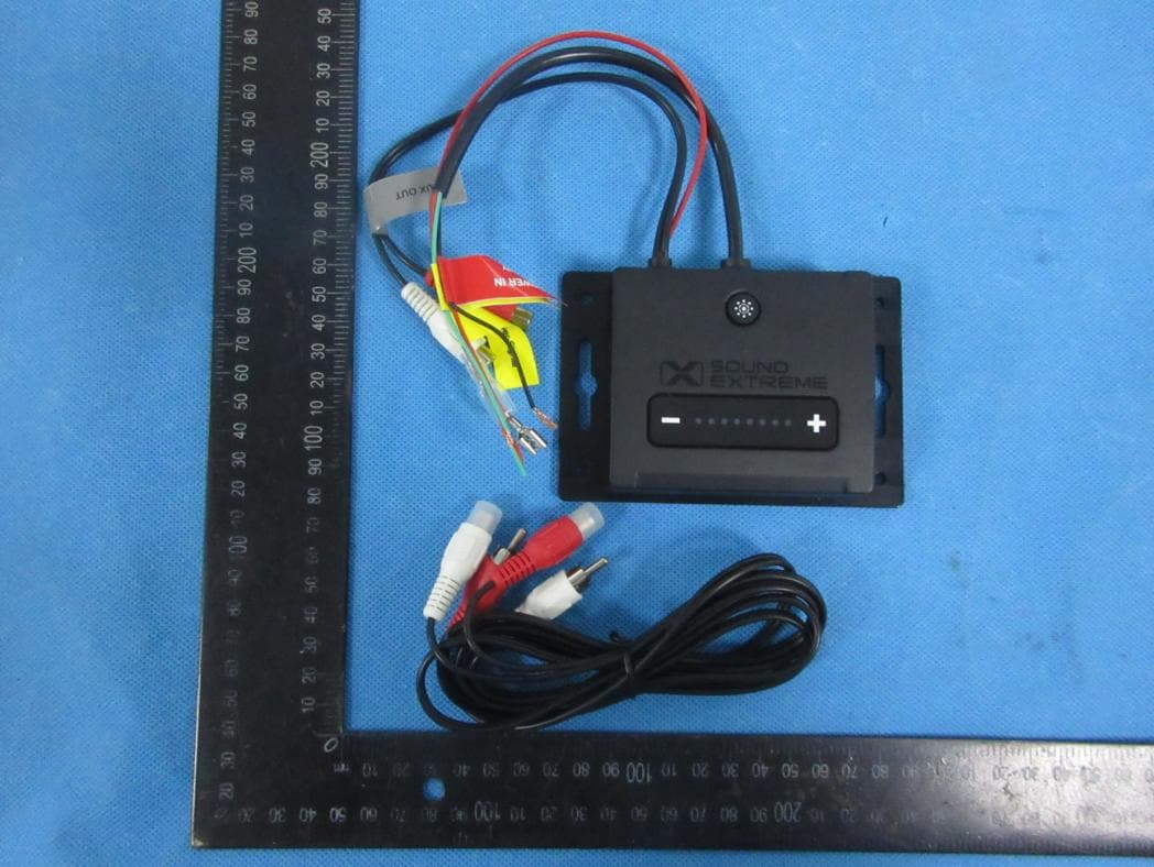
Click to zoom
Application Details
- Equipment Class
- DSS - Part 15 Spread Spectrum Transmitter
- Date of Grant
- May 29, 2023
- Application Purpose
- Original Equipment
- Date of Application
- May 29, 2023
- Equipment Note
- EcoCast Receiver
- Frequency Range
- 2402.00000000 - 2480.00000000
- Company
- Sound Extreme Inc.
- Country
- United States
Documents & Files
Document Text
Text extracted from the exhibit documents filed with the FCC. Open a document above to read the original.
Users Manual
1 ExtremeController Model: SEI-SELEDZ4 4-ZONE LED CONTROLLER User Guide What’s in the Box ExtremeControllerRF Remote Control Remote Turn-On Extension Cable (Dark Blue) – 10 ft long SAE Power Cable – 8 ft long 34 or a technician. Incorrect connections to your vehicle may cause your controller or your vehicle to malfunction. Please note that the maximum voltage for these 4 Vehicle Signal Inputs is 12VDC. · The ExtremeController can be controlled by the included RF Remote or a free SoundExtreme Smartphone App available on the Apple App Store and Google Play Store. · The ExtremeController can support multiple types of SoundExtreme LED products. All 4 Zones come preset to the 6′ ExtremeWhip. To optimize the LED light performance the first time you use the controller, or you make LED Zone connection changes after the initial set up, please use the SoundExtreme Smartphone App to choose the LEDCast product that is connected to each Zone. · The ExtremeController Music Modes work with ECOXGEAR or SoundExtreme products with EcoCast wireless capability. When an LED Zone output is set to Music Mode, the controller needs to wirelessly connect to an EcoCast-enabled audio product. · Do NOT make modifications to the ExtremeController LED connectors or try to connect this product to other manufacturers’ LED products. It may cause permanent damage to the product and VOID THE PRODUCT WARRANTY. · Please read the User Guide before installation and use. · The ExtremeController is compatible with the ECOXGEAR audio and LED lighting EcoSystem, which includes LEDCast and EcoCast Innovations. Look for the LEDCast and EcoCast logos on the growing family of ECOXGEAR and SoundExtreme audio and lighting solutions. · The ExtremeController has four Zone LED Control Outputs. Each Zone supports a maximum power output of 5A. Thus, the total current consumption on the power supply to the ExtremeController depends on how many LEDs are connected to the controller. The maximum current draw is 20A if four 5A units are connected to the controller AND are all lit up at the same time. · Please refer to specifications of your SoundExtreme LED product when you analyze the current-draw requirements of your power supply. · The voltage for the power input is +12VDC. You need to connect to a 12VDC power supply. If your vehicle battery power is not 12V (e.g., 24V, 36V, or 48V), you will need a DC-DC voltage converter with 12V output (e.g. a 48V-to-12V converter). Connecting the ExtremeController directly to higher voltages will cause damage to the controller and VOID THE PRODUCT WARRANTY. · The ExtremeController has a Remote Turn-On Input feature; this is to ensure that the controller is completely powered off (no battery consumption) when your vehicle is not in use. When the input has a signal between 12V to 56V, the controller will turn on. When there is no input voltage, the controller will turn off. In general, this Remote Turn-On signal comes from the vehicle ignition switch. · The ExtremeController has 4 Vehicle Signal Inputs (left turn, right turn, brake, and reverse). When you connect the controller to these inputs, only LED products that are connected to Zones 3 and 4 will be affected. If you are not sure where these signal wires are located on your vehicle, consult your vehicle’s manual ImportantImportant 56 ExtremeController LayoutButton & Connectors ExtremeController OverviewExtremeController Overview Power Input Connector: Power-In SAE Connector (+12V and GND), Remote Turn-On Wire (Dark Blue). · The Power-In SAE cable has an in-line 25 Amp Fuse Holder. · Also included are an 8ft SAE Power Cable and a 10ft Remote Turn-On Extension Cable (Dark Blue). Vehicle Signal Input Connectors: Connect to the vehicle for left turn, right turn, brake, and reverse lighting integration. (This connection is optional; however, you won’t be able to use the Vehicle Signaling Features on your LED product without it.) Multifunction Button: The Button has 3 functions. 1. Short-Press: Re-enable EcoCast audio pairing for LED Music Mode. Zone 1: LED Control Output Connector Zone 3: LED Control Output Connector (Left) Power Inputs: 12V Power-In SAE Connector, Remote Turn-On Wire (Dark Blue) Vehicle Signal Input Connectors: Left Turn, Right Turn, Brake, Reverse Zone 2: LED Control Output Connector Zone 4: LED Control Output Connector (Right) Connection Status LED Indicator Multifunction Button 12V Power-In SAE Connector 8ft Power CableFuse Holder Vehicle Signal Input Connectors: Left Turn, Right Turn, Brake, Reverse Remote Turn-On Wire 10ft Remote Turn-On Extension Cable 78 ExtremeController Overview 2. Double-Click: Enable RF Remote Control pairing. · The included Remote Control already comes paired and is automatically connected to the ExtremeController. · This feature is meant to be used if the connection is lost or a replacement Remote Control is purchased. 3. Press and Hold for 3 seconds: Clears the EcoCast pairing records. Connection Status LED Indicator: The LED indicates 3 possible Connection Statuses. 1. Flashing Blue: The ExtremeController is in Remote Control Pairing Mode. 2. Flashing Green: The ExtremeController is searching for an EcoCast Transmitting device to pair and connect to. 3. Solid Green: The ExtremeController is connected to an EcoCast Transmitting device. LED Control Output Connectors: Connect SoundExtreme LED products to each of the 4 Zone Control Outputs. · All 4 Zone Outputs have the same electric specifications. · Only Zones 3 and 4 integrate with the Vehicle Signal Inputs, allowing the connected LEDs to function as enhanced brake, reverse, and turn signal lights. LED Control Output Connectors Connecting to 12VDC Power Supply The ExtremeController does not have an internal battery. It must be connected to an external 12VDC power supply to function. When you install the ExtremeController to a battery or a voltage regulator on a golf cart, a boat, a quad bike, a UTV, or another vehicle, you need to make sure that your vehicle b…
Text truncated - open the document above for the full version.
Attestation Statements
Sound Extreme Inc. 2.911 (d)(5)(i) Equipment Type Attestation v1.2 Section 2.911(d)(5)(i) Certification – EquipmentType Company name: Sound Extreme Inc. Address: 9212 Fry Road, Suite 105-351, Cypress, TX 77433, USA Product Name: EcoCast Receiver FCC ID: 2BADE-SEISECSTRX Model(s): SEI-SECSTRX 2.911(d)(5)(i) EquipmentType We, [Sound Extreme Inc.] (“the applicant”) certify that the equipment for which authorization is sought through certification is not: Prohibited from receiving an equipment authorization pursuant to § 2.903; of the FCC rules. Identified as an equipment type in the “Covered List” NOTE 1 Yours sincerely, Name: Jamie Florczak Date: 5/18/2023 Title and Company name: EVP / Sound Extreme Inc. NOTE 1 “Covered List”; is the List of Equipment and Services Covered By Section 2 of The Secure Networks Act, available at https://www.fcc.gov/supplychain/coveredlist References; 1) 986446 D01 Covered Equipment v01 https://apps.fcc.gov/oetcf/kdb/forms/FTSSearchResultPage.cfm?switch=P&id=325672 2) Federal Register document 2022-28263 published on 02/06/23 https://www.federalregister.gov/documents/2023/02/06/2022-28263/protecting-against-national-security-threats-to-the-com munications-supply-chain-through-the
Attestation Statements
Sound Extreme Inc. 2.911 (d)(5)(ii) Applicant Attestation v1.3 Section 2.911(d)(5)(ii) Certification – Applicant (Covered List ) Company name: Sound Extreme Inc. Address: 9212 Fry Road, Suite 105-351, Cypress, TX 77433, USA Product Name: EcoCast Receiver FCC ID: 2BADE-SEISECSTRX Model(s): SEI-SECSTRX 2.911(d)(5)(ii) Applicant filing We, [Sound Extreme Inc.] (“the applicant”) certify that, as of the date of the filing of the application, the applicant is not identified NOTE 1 on the “Covered List” NOTE 2 ,established pursuant to §1.50002 of this chapter,as an entity producing coveredcommunications equipment. Yours sincerely, Name: Jamie Florczak Date: 5/18/2023 Title and Company name: EVP / Sound Extreme Inc. NOTE 1 Delete option not applicable to this application. NOTE 2 “Covered List”; is the List of Equipment and Services Covered By Section 2 of The Secure Networks Act, available at https://www.fcc.gov/supplychain/coveredlist References; 1) 986446 D01 Covered Equipment v01 https://apps.fcc.gov/oetcf/kdb/forms/FTSSearchResultPage.cfm?switch=P&id=325672 2) Federal Register document 2022-28263 published on 02/06/23 https://www.federalregister.gov/documents/2023/02/06/2022-28263/protecting-against-national-security-threats-to-the-com munications-supply-chain-through-the
Attestation Statements
Sound Extreme Inc. U.S. Agent Letter of Attestation To: Federal Communications Commission 7435 Oakland Mills Road, Columbia, MD 21046, USA Date: 5/18/2023 Ref: Attestation Statement – Part2.911(d)(7) filing FCC ID: 2BADE-SEISECSTRX Sound Extreme Inc. (“the applicant”) certifies that, as of the date of the filing of the application, Sound Extreme Inc. (“the agent”) is our designated U.S. agent for service of process for the abovereference FCC ID. The applicant accepts to maintain an agent for service of process in the United States forno less than one year after either the grantee has permanently terminated all marketing and importation of theapplicable equipment within the U.S., or the conclusion of any Commission-related administrative or judicialproceeding involving the equipment, whichever is later. The applicant further acknowledges it is ourresponsibility to inform the FCC whenever the agent information changes. Sound Extreme Inc. ("the agent) understand it is the agent's obligation to accept service of process in the United States for matters related to the applicable equipment, and at the physical U.S. address and email address. Designated U.S. Agent Company Name: Sound Extreme Inc. FRN: 0033445503 GC: 2BADE Address: 9212 Fry Road, Suite 105-351, Cypress, TX 77433, USA Signature: Contact Person: Jamie Florczak Tel: (858) 208-9530 Email: [email protected] Applicant Company Name: Sound Extreme Inc. Address: 9212 Fry Road, Suite 105-351, Cypress, TX 77433, USA Signature: Contact Person: Jamie Florczak Tel: (858) 208-9530 Email: [email protected]
Cover Letter(s)
Sound Extreme Inc. Office of Engineering Technology Federal Communications Commission 7435 Oakland Mills Road Columbia, MD 21046 USA Date: 5/18/2023 Subject; Request for Confidentiality FCC ID: 2BADE-SEISECSTRX To Whom It May Concern, Pursuant to the provisions of the Commission’s rules Title 47 Sections §0.457 and §0.459, we are requesting the Commission to withhold the following attachment(s) as confidential documents from public disclosure indefinitely. These documents contain detailed system and equipment descriptions and are considered as proprietary information in operation of the equipment. The public disclosure of these documents might be harmful to our company and would give competitors an unfair advantage in the market. Schematic Diagram Block Diagram Parts List Operational Description SOFTWARE SECURITY REQUIREMENTS FOR U-NII DEVICES In additional to above mentioned documents, in order to comply with the marketing regulations in Title 47 CFR §2.803 and the importation rules in Title 47 CFR §2.1204, while ensuring that business sensitive information remains confidential until the actual marketing of newly authorized devices, we request Short Term Confidentiality of the following attachment(s); External Photos Test Setup Photos Internal Photos User Manual For 45 days, pursuant to Public Notice DA 04-1705. OR For 180 days pursuantto KDB 726920 D01. It is our understanding that all measurement test reports, FCC ID label format and correspondence during the certification review process cannot be granted as confidential documents and this information will be available for public review once the grant of equipment authorization is issued. Sincerely, Signature: Name: Jamie Florczak Title: EVP Email: [email protected]
Cover Letter(s)
Sound Extreme Inc. Date:5/18/2023 FCC ID: 2BADE-SEISECSTRX Model Number: SEI-SECSTRX To: Federal Communication Commission Authorization and Evaluation Division 7435 Oakland Mills Road Columbia, MD 21048 To Whom It May Concern, We, Sound Extreme Inc. declare that this EUT (FCC ID: 2BADE-SEISECSTRX) will conduct FCC compliance testing, the SDOC part recognized test lab(Shenzhen NTEK Testing Technology Co., Ltd.( ShenZhen Lab.). 1/F, Building E, Fenda Science Park, Sanwei Community,Xixiang Street Bao’an District, Shenzhen 518126 P.R. China) Please contact me if you have any question. Sincerely, (Signed) Name / Title: Jamie Florczak/ EVP Company: Sound Extreme Inc. Address: 9212 Fry Road, Suite 105-351, Cypress, TX 77433, USA
Cover Letter(s)
Letter of Authorization Company: Sound Extreme Inc. Address: 9212 Fry Road, Suite 105-351, Cypress, TX 77433, USA Product Name: EcoCast Receiver Model Number: SEI-SECSTRX FCC Identifier: 2BADE-SEISECSTRX We authorize MiCOM Labs Inc, 575 Boulder Court, Pleasanton, California 94566, USA, to act on our behalf on all matters concerning the above named equipment. Any individual within MiCOM Labs is authorized to act on our behalf and take action on the application. We declare that MiCOM Labs Inc, 575 Boulder Court, Pleasanton, California 94566, USA, is allowed to forward all information related to the approval project to the Federal Communication Commission and to discuss any issues concerning the approval application. Any and all acts carried out by MiCOM Labs on our behalf shall have the same effect as acts of our own. Name: Jamie Florczak Date: 5/18/2023 Title: EVP Signature of applicant:
External Photos
ATTACHMENT PHOTOGRAPHS OF EUT Photo 1 Photo 2 Photo 3 Photo 4 Photo 5 Photo 6
Internal Photos
Photo 7 Photo 8 Photo 9 Photo 10 BT ANT
RF Exposure Info
FCC ID: 2BADE-SEISECSTRX RF EXPOSURE EVALUATION According to FCC 1.1310: The criteria listed in the following table shall be used to evaluate the environment impact of human exposure to radio frequency(RF) Radiation as specified in §1.1307(b) Limits for Maximum Permissible Exposure (MPE) MPE Calculation Method E (V/m) = d GP**30 Power Density: Pd (W/m²) = 377 2 E E = Electric field (V/m) P = Average RF output power (W) G = EUT Antenna numeric gain (numeric) d = Separation distance between radiator and human body (m) The formula can be changed to Pd = 2 *377 **30 D GP From the EUT RF output power, the minimum mobile separation distance, d=0.2m, as well as the gain of the used antenna, the RF power density can be obtained. Measurement Result Operation Frequency: BR+EDR: 2402-2480MHz Power density limited: 1mW/ cm 2 Antenna Type: PCB Antenna Antenna gain: 0 dBi, R=20cm conducted power Evaluation result Power density Limits (dBm)(mW)(dBi)Numeric 2402 8.38 8±19 7.9430.001.000.00161 2441 8.92 8±19 7.9430.001.000.00161 2480 8.98 8±19 7.9430.001.000.00161 2402 6.73 7±18 6.3100.001.000.00131 2441 7.31 7±18 6.3100.001.000.00131 2480 7.07 7±18 6.3100.001.000.00131 2402 7.4 7±18 6.3100.001.000.00131 2441 7.9 7±18 6.3100.001.000.00131 2480 7.53 7±18 6.3100.001.000.00131 8-DPSK (mW/cm2 )(mW/cm2) Antenna Gain GFSK Max tune-up power Channel Freq. (MHz) modulation Tune-up power (dBm) (dBm) π/4-DQPSK Conclusion: For the max result : 0.0016≤ 1.0 for Max Power Density, compliance RF exposure.. Signature: Date: 5/19/2023 NAME AND TITLE (Please print or type): Alex Li/Manager COMPANY (Please print or type): Shenzhen NTEK Testing Technology Co., Ltd./ 1/F, Building E, Fenda Science Park, Sanwei Community, Xixiang Street Bao’an District, Shenzhen P.R. China.
Test Report
Parameter Testing Report Project:WIFI Antenna Product Description 2400-2500MHz Report Date: 2022.02.24 Report Version: 1.0 Prepared by: Patrick Approved by: Jammy 2022.10.24 2 Contents: 1. Testing Item & Equipment 2. S-Parameters Test Results 3. GAIN & Efficiency TEST PAANT101 COANT1 Antenna appearance figure 3 1. Testing Item & Equipment 4 2.VSWR TEST GAIN& Efficiency TEST 参数 \ 频率 (mhz) 2400 2450 2500 Peak Gain(dBi) -2.870.00-1.15 Efficiency(%) 56.48 58.21 61.38 Response (dB) -14 0 -12 -10 -8 -6 -4 -2 2450 MHz
Test Report
Report No.: S22120803202001 Version.1.3 Page 1 of 93 RADIO TEST REPORT FCC ID: 2BADE-SEISECSTRX Product: EcoCast Receiver Trade Mark: ECOXGEAR Model No.: SEI-SECSTRX Family Model: N/A Report No.: S22120803202001 Issue Date: Jan 13. 2023 Prepared for Sound Extreme Inc. 9212 Fry Road, Suite 105-351, Cypress, TX 77433, USA Prepared by Shenzhen NTEK Testing Technology Co., Ltd. 1/F, Building E, Fenda Science Park, Sanwei Community, Xixiang Street Bao’an District, Shenzhen 518126 P.R. China Tel. 400-800-6106, 0755-2320 0050, 0755-2320 0090 Website: http://www.ntek.org.cn Report No.: S22120803202001 Version.1.3 Page 2 of 93 TABLE OF CONTENTS 1 TEST RESULT CERTIFICATION ...................................................................................................................... 3 2 SUMMARY OF TEST RESULTS ......................................................................................................................... 4 3 FACILITIES AND ACCREDITATIONS ............................................................................................................. 5 3.1 FACILITIES..................................................................................................................................................... 5 3.2 LABORATORY ACCREDITATIONS AND LISTINGS ................................................................................. 5 3.3 MEASUREMENT UNCERTAINTY ............................................................................................................... 5 4 GENERAL DESCRIPTION OF EUT .................................................................................................................. 6 5 DESCRIPTION OF TEST MODES ..................................................................................................................... 8 6 SETUP OF EQUIPMENT UNDER TEST ........................................................................................................... 9 6.1 BLOCK DIAGRAM CONFIGURATION OF TEST SYSTEM ....................................................................... 9 6.2 SUPPORT EQUIPMENT ............................................................................................................................... 10 6.3 EQUIPMENTS LIST FOR ALL TEST ITEMS .............................................................................................. 11 7 TEST REQUIREMENTS .................................................................................................................................... 12 7.1 CONDUCTED EMISSIONS TEST ............................................................................................................... 12 7.2 RADIATED SPURIOUS EMISSION ............................................................................................................ 14 7.3 NUMBER OF HOPPING CHANNEL ........................................................................................................... 23 7.4 HOPPING CHANNEL SEPARATION MEASUREMENT ........................................................................... 24 7.5 AVERAGE TIME OF OCCUPANCY (DWELL TIME) ................................................................................ 25 7.6 20DB BANDWIDTH TEST .......................................................................................................................... 27 7.7 PEAK OUTPUT POWER .............................................................................................................................. 28 7.8 CONDUCTED BAND EDGE MEASUREMENT......................................................................................... 29 7.9 SPURIOUS RF CONDUCTED EMISSION .................................................................................................. 30 7.10 ANTENNA APPLICATION .......................................................................................................................... 31 7.11 FREQUENCY HOPPING SYSTEM (FHSS) EQUIPMENT REQUIREMENTS ......................................... 32 8 TEST RESULTS ................................................................................................................................................... 33 8.1 DWELL TIME ................................................................................................................................................... 33 8.2 MAXIMUM CONDUCTED OUTPUT POWER ....................................................................................................... 43 8.3 -20DB BANDWIDTH ........................................................................................................................................ 49 8.4 OCCUPIED CHANNEL BANDWIDTH .................................................................................................................. 55 8.5 CARRIER FREQUENCIES SEPARATION .............................................................................................................. 61 8.6 NUMBER OF HOPPING CHANNEL ..................................................................................................................... 67 8.7 BAND EDGE .................................................................................................................................................... 70 8.8 BAND EDGE(HOPPING) ................................................................................................................................... 77 8.9 CONDUCTED RF SPURIOUS EMISSION ............................................................................................................. 84 Report No.: S22120803202001 Version.1.3 Page 3 of 93 1 TEST RESULT CERTIFICATION Applicant’s name ........................ : Sound Extreme Inc. Address ....................................... : 9212 Fry Road, Suite 105-351, Cypress, TX 77433, USA Manufacturer's Name ................. : Xingtel Xiamen Group Co., Ltd. Address ....................................... : Xingtel Building,Chuangxin Road, Torch Hi-Tech Indus…
Text truncated - open the document above for the full version.
Test Setup Photos
Radiated Measurement Photos
Contact Information
Applicant
Jamie Florczak
Technical Contact
Test Firm
Shenzhen NTEK Testing Technology Co., Ltd.Alex Li
[email protected]+86-755-6115-9384
Technical Specifications
| # | Rule Parts | Frequency Range | Power Output |
|---|---|---|---|
| 1 | 15C | 2.40 GHz - 2.48 GHz | 7.91 mW |
Other Applications from Sound Extreme Inc.
2BADE-SELEDZ4OEM
Jan 26, 2026LED 4 Zone Controller OEM version
Equipment Class
DTS - Digital Transmission System2BADE-SEIPLSB2801
Dec 26, 2025SEB PULSE
Equipment Class
DTS - Digital Transmission System2BADE-SEIPLS2801
Sep 30, 2025PULSE28
Equipment Class
DTS - Digital Transmission System2BADE-GMRS15
Aug 12, 2024Mobile Radio
Equipment Class
TNB - Licensed Non-Broadcast Station Transmitter2BADE-SEISE18E01
Jan 17, 2024SOUNDEXTREME SE18E
Equipment Class
DTS - Digital Transmission System