2BAGQ-3RVS01031ZSmart Vibration Sensor
Jiangsu Shushi Technology Co., Ltd.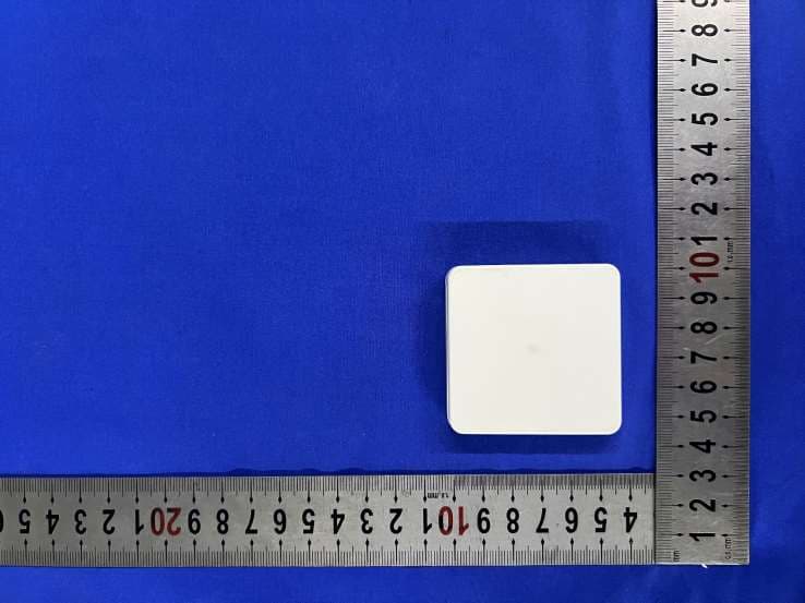
Click to zoom
Application Details
- Equipment Class
- DTS - Digital Transmission System
- Date of Grant
- Jun 28, 2023
- Application Purpose
- Original Equipment
- Date of Application
- Jun 28, 2023
- Equipment Note
- Smart Vibration Sensor
- Frequency Range
- 2405.00000000 - 2480.00000000
- Country
- China
Documents & Files
Document Text
Text extracted from the exhibit documents filed with the FCC. Open a document above to read the original.
Users Manual
Vibration Sensor Quick Start Guide Introduction Specification Third Reality Zigbee Vibration Sensor can be used to detect the vibration and movement of objects, it is designed for indoor use only. It can be integrated into Amazon Alexa, SmartThings, Hubitat, Home Assistant and Third Reality App etc. through Zigbee protocol, it can be used to create routines like alerts of window breaks and washing machines/dryers monitoring etc. Operating Temp Power Supply Dimensions Protocol 32 to 104 F(0 to 40 °C) Indoor Use Only 2 × AAA Batteries 2.19" × 2.20" × 0.48" ( 5.56cm×5.59cm ×1.23cm) Zigbee 3.0 Senitivity Setting:Siren Setting: 0 ONOFF 1 00 Very HighHighMediumLow 110110 Setup Simply place the Vibration Sensor on top of the object to be monitored, or use double-sided tape to stick it anywhere as desired. Remove the plastic insulator to power the Vibration Sensor. When the sensor is powered up for the first time, it enters pairing mode automatically, and it exits pairing mode if not paired within 3 minutes, to put it into pairing mode again by pressing the reset button for 5 seconds. Follow the instructions of Zigbee hubs to pair the sensor. Turn on/off the beeping alarm with the single toggle switch, and set the sensitivity(4 levels) with the dual toggle switches. 1. 2. 3. Installation This device complies with part 15 of the FCC rules. Operation is subject to the following two conditions: (1) this device may not cause harmful interference, and (2) this device must accept any interference received, including interference that may cause undesired operation. Changes or modifications not expressly approved by the party responsible for compliance could void the user’s authority to operate the equipment. NOTE: This equipment has been tested and found to comply with the limits for a Class B digital device, pursuant to part 15 of the FCC Rules. These limits are designed to provide reasonable protection against harmful interference in a residential installation. FCC Regulatory Conformance This equipment generates uses and can radiate radio frequency energy and, if not installed and used in accordance with the instructions, may cause harmful interference to radio communi- cations. However, there is no guarantee that interference will not occur in a particular installation. If this equipment does cause harmful interference to radio or television reception, which can be determined by turning the equipment off and on, the user is encouraged to try to correct the interference by one or more of the following measures: ‐Reorient or relocate the receiving antenna. ‐Increase the separation between the equipment and receiver. ‐Connect the equipment into an outlet on a circuit different from that to which the receiver is connected. ‐Consult the dealer or an experienced radio/TV technician for help important announcement Important Note: NOTE: The manufacturer is not responsible for any radio or TV interference caused by unauthorized modifications to this equipment. Such modifications could void the user’s authority to operate the equipment. RF Exposure This equipment complies with FCC radiation exposure limits set forth for an uncontrolled environment. This transmitter must not be co-located or operating in conjunc- tion with any other antenna or transmitter. This equipment generates uses and can radiate radio frequency energy and, if not installed and used in accordance with the instructions, may cause harmful interference to radio communi- cations. However, there is no guarantee that interference will not occur in a particular installation. If this equipment does cause harmful interference to radio or television reception, which can be determined by turning the equipment off and on, the user is encouraged to try to correct the interference by one or more of the following measures: ‐Reorient or relocate the receiving antenna. ‐Increase the separation between the equipment and receiver. ‐Connect the equipment into an outlet on a circuit different from that to which the receiver is connected. ‐Consult the dealer or an experienced radio/TV technician for help important announcement Important Note: Limited Warranty For limited warranty, please visit www.3reality.com/devicesupport For customer support, please contact us at [email protected] or visit www.3reality.com For help and troubleshooting related to Amazon Alexa, visit the Alexa app.
External Photos
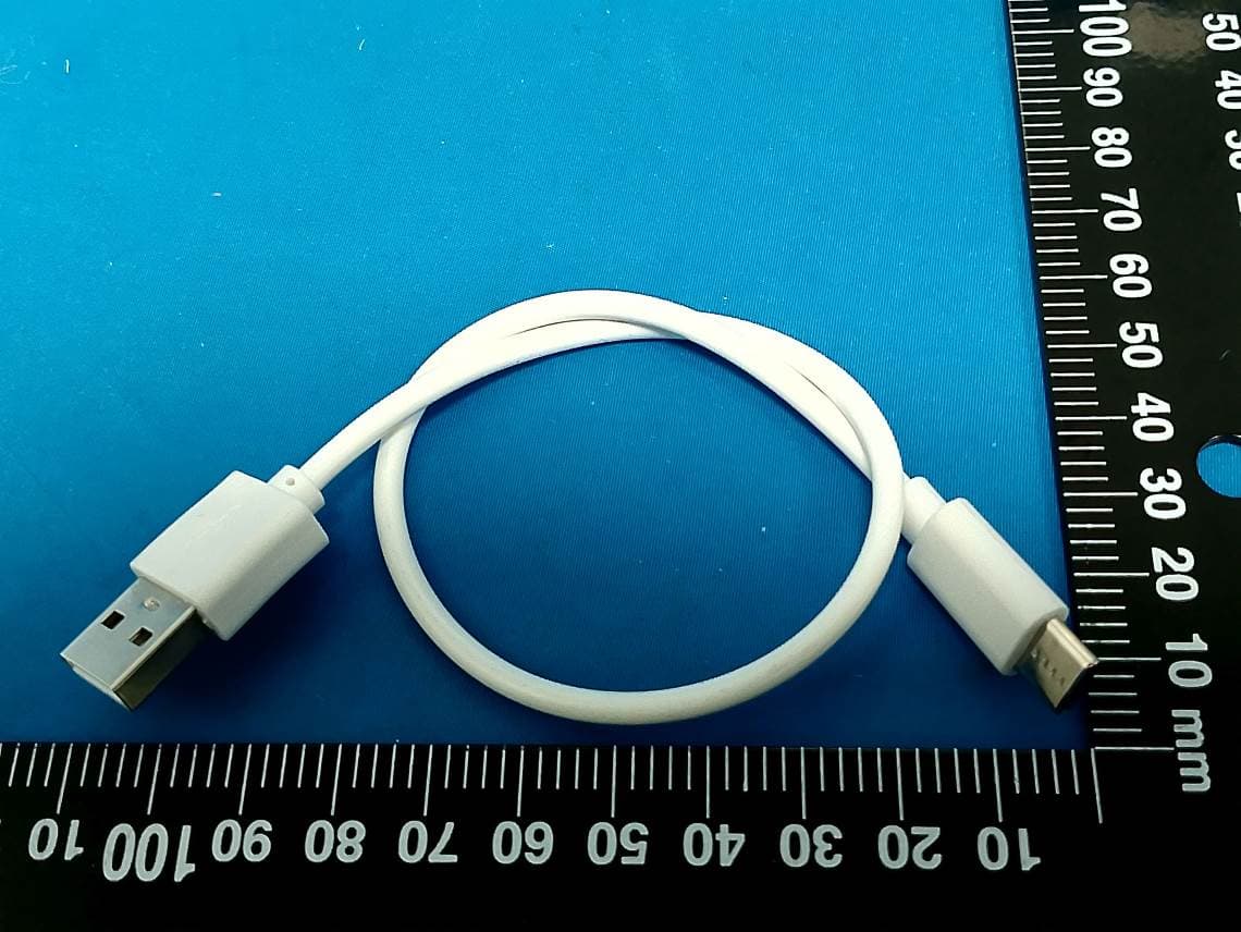
External Photos Photo 1: General view Photo 2: General view Photo 3: General view Photo 4: General view Photo 5: General view Photo 6: General view
Internal Photos
InternalPhotos Photo1:PCBview Photo2:PCBview Photo3:PCBview Photo4:PCBview Antenna
Operational Description
Declaration Jiangsu Shushi Technology Co., Ltd. We declara that the label of this product is placed on the back cover. The back cover is an indispensable part of this product. The shell is designed for the upper and lower covers, the bottom cover contains the battery cover function, the function of protecting the circuit board, and the most important thing is that the upper and lower covers must be combined into one and pasted to the tested item to detect vibration, LED light display in the upper cover area, etc. The slide is designed to make it easy for users to use the pairing buttons, up and down batteries, etc. Regards, Wei Chen / Manager
RF Exposure Info
Fangguang Inspection & Testing Co., Ltd. Page Number: 1 of 5 RF Exposure Evaluation Declaration Report No.: S202305080812E06 Issue Date: 06-27-2023 Applicant: Jiangsu Shushi Technology Co., Ltd. Address: NO.9 Nanxu Road,RunZhou District,Zhenjiang, Jiangsu,China FCC ID: 2BAGQ-3RVS01031Z Application Type: Certification Product: Smart Vibration Sensor Model No.: 3RVS01031Z Trade Mark: / FCC Classification: Digital Transmission System (DTS) FCC Rule Part(s): Part 15 Subpart C (15.247) Test Procedure(s): ANSI C63.10-2013, KDB 558074 D01v05r02 Test Date: May 29, 2023 Compiled By K_主检”、“K_审核”、“K_批准 (Amos Xia) Senior Test Engineer Approved By (Line Chen) Engineer Manager The test results relate only to the samples tested. This equipment has been shown to be capable of compliance with the applicable technical standards as indicated in the measurement report and was tested in accordance with the measurement procedures specified in KDB 558074 D01. Test results reported herein relate only to the item(s) tested. The test report shall not be reproduced except in full without the written approval of Fangguang Inspection & Testing Co., Ltd. Wuxi Branch The test report must not be used by the client to claim product certifications, approval, or endorsement by NVLAP, NIST or any agency of U.S. Government. Report No.: S202305080812E06 Page Number: 2 of 5 Revision History Report No. Version Description Issue Date S202305080812E06 Rev. 01 / 06-27-2023 Report No.: S202305080812E06 Page Number: 3 of 5 1. PRODUCT INFORMATION 1.1. Equipment Description 1.2. Product Specification Subjective to this Report Product Name: Smart Vibration Sensor Model Name: 3RVS01031Z Trade Mark: / Input Voltage Range: Input: DC 3V Zigbee Version: 3.0 Frequency Range 2405-2480 MHz Number of Channels Zigbee: 16 Channel Spacing Zigbee: 5MHz Antenna Gain 2 dBi Type of Modulation Zigbee: O-QPSK Report No.: S202305080812E06 Page Number: 4 of 5 2. RF Exposure Evaluation 2.1. Limits According to KDB447498 D01 General RF Exposure Guidance v06 Section 4.3.1 Standalone SAR test exclusion considerations: “Unless specifically required by the published RF exposure KDB procedures, standalone 1-g head or body and 10-g extremity SAR evaluation for general population exposure conditions, by measurement or numerical simulation, is not required when the corresponding SAR Test Exclusion Threshold condition, listed below, is satisfied. These test exclusion conditions are based on source-based time-averaged maximum conducted output power of the RF channel requiring evaluation, adjusted for tune-up tolerance, and the minimum test separation distance required for the exposure conditions. The minimum test separation distance is determined by the smallest distance from the antenna and radiating structures or outer surface of the device, according to the host form factor, exposure conditions and platform requirements, to any part of the body or extremity of a user or bystander (see 5) of section 4.1). To qualify for SAR test exclusion, the test separation distances applied must be fully explained and justified by the operating configurations and exposure conditions of the transmitter and applicable host platform requirements, typically in the SAR measurement or SAR analysis report, according to the required published RF exposure KDB procedures. When no other RF exposure testing or reporting is required, a statement of justification and compliance must be included in the equipment approval, in lieu of the SAR report, to qualify for the SAR test exclusion. When required, the device specific conditions described in the other published RF exposure KDB procedures must be satisfied before applying these SAR test exclusion provisions; for example, handheld PTT two-way radios, handsets, laptops & tablets etc. “ [(max. power of channel, including tune-up tolerance, mW)/ (min. test separation distance, mm)] · [VF (GHz)] ≤ 3.0 for 1-g SAR and≤ 7.5 for 10-g extremity SAR, where: • f (GHz) is the RF channel transmit frequency in GHz • Power and distance are rounded to the nearest mW and mm before calculation • The result is rounded to one decimal place for comparison • 3.0 and 7.5 are referred to as the numeric thresholds in the step 2 below The test exclusions are applicable only when the minimum test separation distance is ≤ 50 mm and for transmission frequencies between 100 MHz and 6 GHz. When the minimum test separation distance is < 5 mm, a distance of 5 mm according to f) in section 4.1 is applied to determine SAR test exclusion. Report No.: S202305080812E06 Page Number: 5 of 5 2.2. Calculation Method [(max. power of` channel, including tune-up tolerance, mW)/(min. test separation distance, mm)] ·[√f(GHz)] ≤ 3.0 Conducted Power + tune up tolerance =1.21dBm=1.32mW Distance = 5 mm f =2.48 [1.32/5] * SQRT(2.48) =0.42 0.42 ≤ 3.0 Therefore, excluded from SAR testing. CONCULISON: The measurement results comply with the FCC Limit per 47 CFR 2.1093 for the uncontrolled RF Exposure and SAR Exclusion Threshold per KDB 447498 v06. The End
Test Report
2.4G PCB Antenna Specification Manufacturer: Jiangsu Shushi Technology Co., Ltd. Address: NO.9 Nanxu Road,RunZhou District,Zhenjiang,Jiangsu,China Model: 3RVS01031Z‐PCBANT Frequency: 2400 ‐ 2500MHZ Peak Gain: 2.0dBi Free Space Radiation Pattern: Antenna Dimensions: Length≈1/4*λ≈30mm, width: 1mm Operating Temperature: ‐10°C ~ +50°C Storage Temperature: ‐10°C ~ +50°C
Test Report
Fangguang Inspection & Testing Co., Ltd. Headquarters Add.: Area B of the 3rd floor, XEDA Sci-Tech Park, Xiqing Economic Development Area, Tianjin, China Tel:+86-020-66289500-8260 Email: [email protected] http://www.fgtest.cn TRF No.:FG.WI-07-Part 15 Subpart C (15.247) Reports Inquiry :https://grgtest.com Page Number: 1 of 60 Report No.: S202305080812E05 I s s u e D a t e : 06-27-2 0 2 3 Applicant: Jiangsu Shushi Technology Co., Ltd. Address: NO.9 Nanxu Road,RunZhou District,Zhenjiang, Jiangsu,China FCC ID: 2BAGQ-3RVS01031Z Product: Smart Vibration Sensor Model No.: 3RVS01031Z FCC Classification: Digital Transmission System (DTS) FCC Rule Part(s): Part 15 Subpart C (15.247) Test Procedure(s): ANSI C63.10-2013, KDB 558074 D01v05r02 Result: Pass Item Receipt Date: May 12, 2023 Test Date: May 29, 2023 MEASUREMENT REPORT FCC PART 15.247 Zigbee Compiled By (Amos Xia) Senior Test Engineer Approved By (Line Chen) Engineer Manager The test results relate only to the samples tested. This equipment has been shown to be capable of compliance with the applicable technical standards as indicated in the measurement report and was tested in accordance with the measurement procedures specified in ANSI C63.4-2014. Test results reported herein relate only to the item(s) tested. The test report shall not be reproduced except in full without the written approval of Fangguang Inspection & Testing Co., Ltd. Wuxi Branch The test report must not be used by the client to claim product certifications, approval, or endorsement by NVLAP, NIST or any agency of U.S. Government. Report No.: S202305080812E05 Page Number: 2 of 60 Revision History Report No. Version Description Issue Date S202305080812E05 Rev. 01 / 06-27-2023 Report No.: S202305080812E05 Page Number: 3 of 60 CONTENTS Description Page §2.1033 General Information ..........................................................................................................5 1. INTRODUCTION ..........................................................................................................................6 1.1. Scope .................................................................................................................................6 1.2. Fangguang Test Location ...................................................................................................6 2. PRODUCT INFORMATION ..........................................................................................................7 2.1. Equipment Description ........................................................................................................7 2.2. Product Specification Subjective to this Report ...................................................................7 2.3. Operation Frequency / Channel List ...................................................................................8 2.4. Device Capabilities .............................................................................................................8 2.5. Description of Test Software ...............................................................................................8 2.6. Test Mode ..........................................................................................................................8 2.7. Test Configuration ..............................................................................................................9 2.8. EMI Suppression Device(s)/Modifications ...........................................................................9 2.9. Labeling Requirements .......................................................................................................9 2.10. Calculation with all conversion and correction factors used ..............................................9 3. DESCRIPTION OF TEST ........................................................................................................... 10 3.1. Evaluation Procedure ....................................................................................................... 10 3.2. AC Line Conducted Emissions ......................................................................................... 10 3.3. Radiated Emissions .......................................................................................................... 11 4. ANTENNA REQUIREMENTS ..................................................................................................... 12 5. TEST EQUIPMENT CALIBRATION DATE ................................................................................. 13 6. MEASUREMENT UNCERTAINTY .............................................................................................. 14 7. TEST RESULT ............................................................................................................................ 15 7.1. Summary .......................................................................................................................... 15 7.2. 6dB Bandwidth Measurement ........................................................................................... 16 7.2.1. Test Limit ....................................................................................................................... 16 7.2.2. Test Procedure used ...................................................................................................... 16 7.2.3. Test Setting .................................................................................................................... 16 7.2.4. Test Setup ...................................................................................................................... 16 7.2.5. Test Result ..................................................................................................................... 17 7.3. Output Power Measurement ............................................................................................. 20 7.3.1. Test Limit ......................................................................................…
Text truncated - open the document above for the full version.
Test Setup Photos
TestSetupPhotos RadiatedEmissionTestSetupfor30MHz~1GHz RadiatedEmissionTestSetupforAbove1GHz ConductedTestSetup
Contact Information
Applicant
Wei Chen(Manager)
Test Firm
Fangguang Inspection & Testing Co. LtdZeming Zhang
[email protected]135-7047-5374
Technical Specifications
| # | Rule Parts | Frequency Range | Power Output |
|---|---|---|---|
| 1 | 15C | 2.40 GHz - 2.48 GHz | 1.32 mW |
Other Applications from Jiangsu Shushi Technology Co., Ltd.
2BAGQ-3RPL01084Z
May 27, 2026Multi-Function Smart Presence Sensor R3
Equipment Class
FDS - Part 15 Field Disturbance Sensor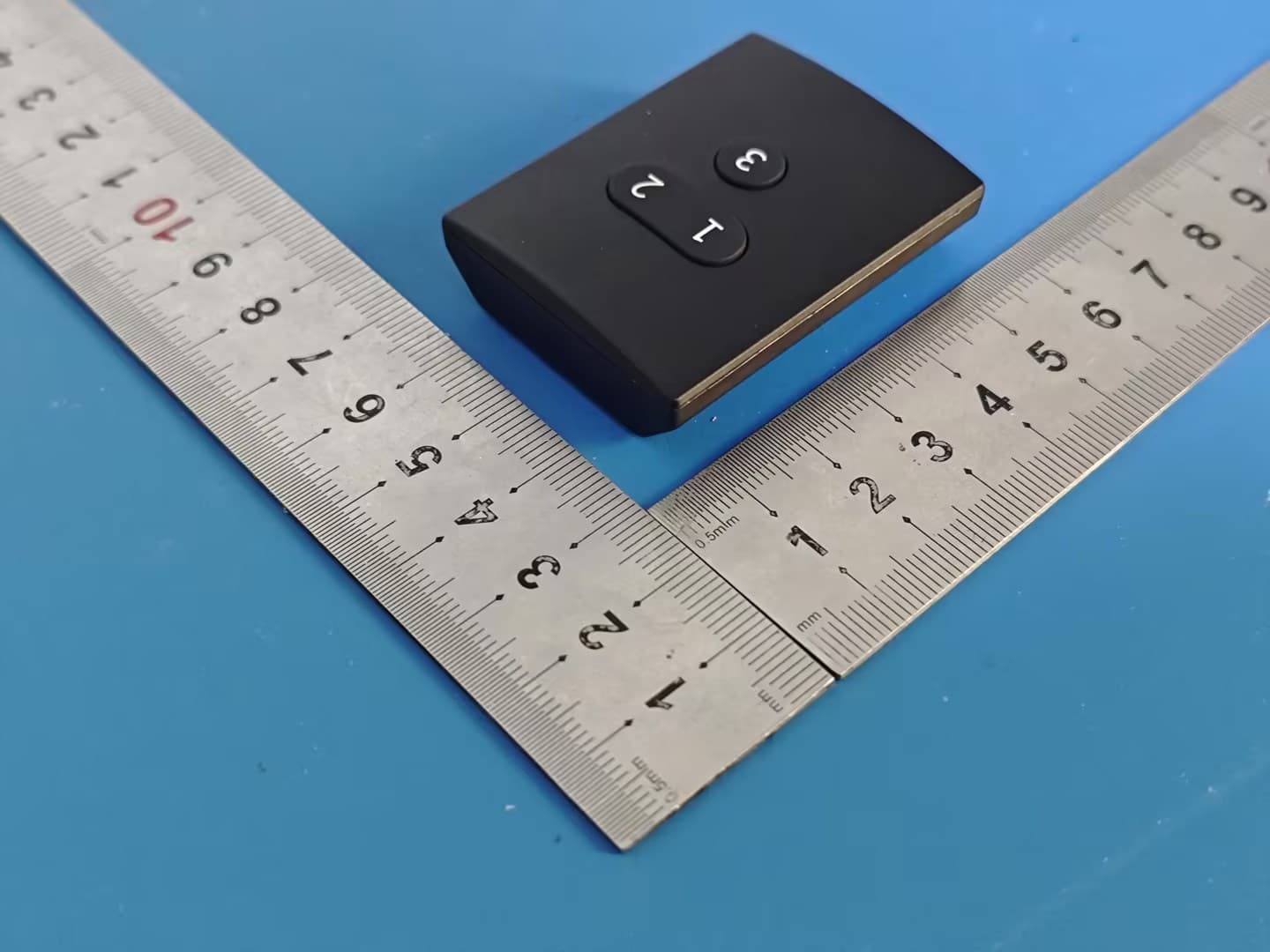
2BAGQ-3RSB01085Z
Apr 28, 2026Smart Button ZB2
Equipment Class
DTS - Digital Transmission System
2BAGQ-3RSM0347Z
Feb 07, 2026Smart Soil Moisture Sensor Gen2
Equipment Class
DTS - Digital Transmission System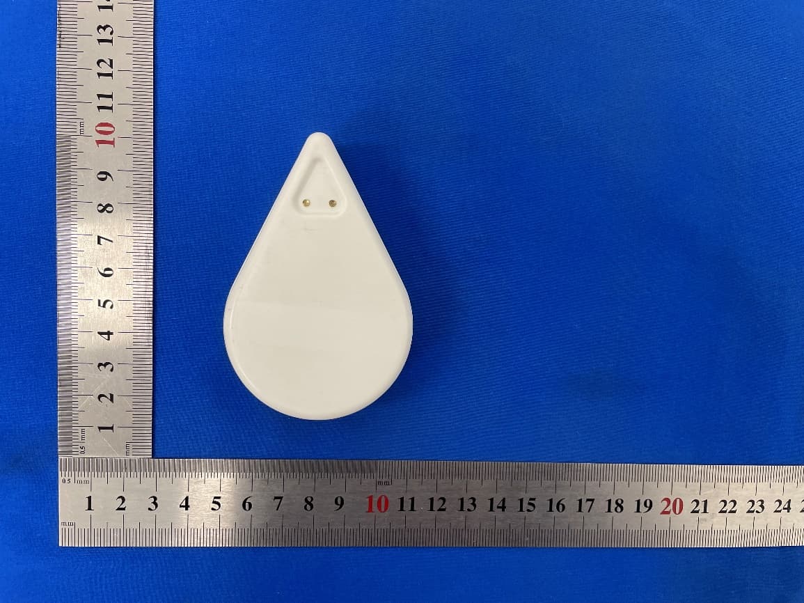
2BAGQ-3RWLK01068S
Nov 17, 2025Smart WaterLeak Sensor KM1
Equipment Class
DXX - Part 15 Low Power Communication Device Transmitter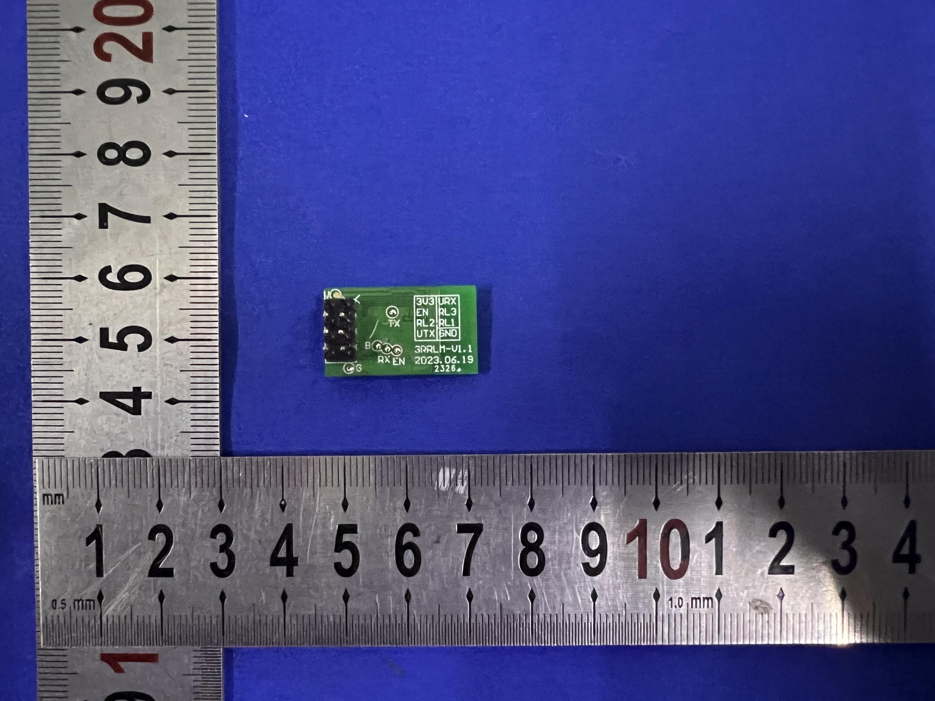
2BAGQ-3RSR01045W
Sep 13, 2023BL602 Matter Wi-Fi Relay
Equipment Class
DTS - Digital Transmission System