2BAH6-SU601The Battery Monitor provides critical system information including battery voltage, current, State of Charge (SoC) and temperature information of the auxiliary battery via the RedVision App.
REDARC ELECTRONICS PTY LTD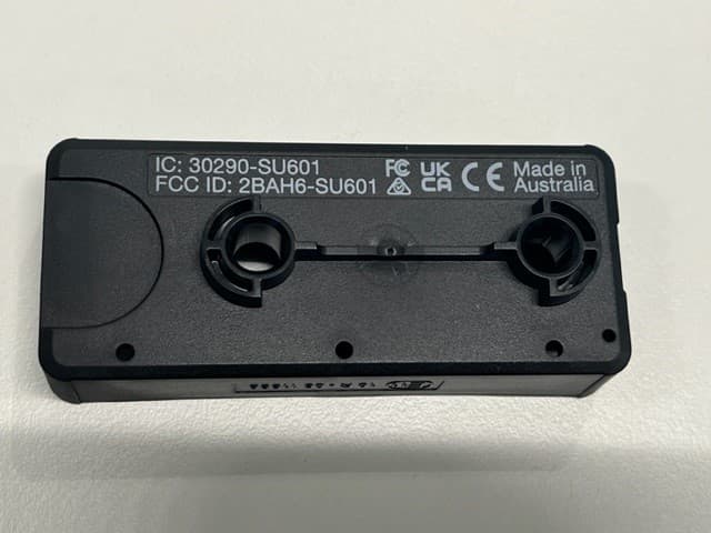
Click to zoom
Application Details
- Equipment Class
- DTS - Digital Transmission System
- Date of Grant
- Oct 03, 2023
- Application Purpose
- Original Equipment
- Date of Application
- Oct 03, 2023
- Equipment Note
- The Battery Monitor provides critical system information including battery voltage, current, State of Charge (SoC) and temperature information of the auxiliary battery via the RedVision App.
- Frequency Range
- 2402.00000000 - 2480.00000000
- Company
- REDARC ELECTRONICS PTY LTD
- Country
- Australia
Documents & Files
Document Text
Text extracted from the exhibit documents filed with the FCC. Open a document above to read the original.
Users Manual
Installation — Wiring | 15 R-BUS CABLE CONNECTION IMPORTANT: The Battery Monitor is not designed to be used alone with the RedVision® Display. DO NOT connect computers or IT equipment to the R-Bus socket. This may damage internal components. CONNECTING THE BATTERY MONITOR TO THE REDVISION ® SYSTEM The supplied R-Bus cable is used to connect the Battery Monitor to the RedVision ® system. Connect one end of the R-Bus cable to the RBUS socket on the Battery Monitor. Then, connect the other end of the cable to any available R-Bus (CAN) socket on the Manager or other compatible REDARC Products with a R-Bus system. NOTE: Leave a minimum of 100 mm (4") of clearance around the RBUS socket on the Battery Monitor to allow routing of the R-Bus cable. Min. 100 mm (4") of clearance REDARC Manager REDVISION ® SYSTEM SETUP EXAMPLE To incorporate the Battery Monitor into your R-Bus system, connect the devices in a continuous daisy-chain network. Terminating Resistors must be present at each end of the daisy-chain to complete the R-Bus system (supplied with the Manager). The Battery Monitor has its own built in terminating resistor. An example is shown below. TVMS System Installation Example Display Battery Monitor R-Bus (RJ45) Cables Terminating Resistor (Inbuilt) Terminating Resistor Manager 16 | Installation — Wiring BATTERY SENSE LEAD CONNECTION Insert the Battery Sense Connector on the Battery Sense Lead into the B POS + socket on the Battery Monitor. Then, connect the Battery Sense Lug to the auxiliary battery positive (+) terminal using appropriate fasteners to secure. IMPORTANT: Do not fit the Battery Sense Lead between the auxiliary battery and lugs carrying high currents. Auxiliary Battery Battery Sense Connector Battery Sense Lug STRAIN-RELIEF AND CABLE MANAGEMENT CAUTION: Wiring must be installed in protected areas away from heat sources and sharp objects or over/through parts of the vehicle that move during operation or maintenance. Additional protection such as conduit may be required, especially is routing cables through the engine bay. NOTICE: Do not bottom-out the thread when screwing the bolt into the terminal, this may cause a poor electrical connection. IMPORTANT: Ensure lugs are fastened firmly against the top face of the terminal. Loose lugs will have a bad electrical connection, causing inaccurate readings from the Battery Monitor, and can result in damage to the wiring and Battery Monitor. Good ConnectionLoose Connection Lug tongue facing downwards and is not long enough to fasten flush to the shunt. Do not use the longer Alternative Terminal Bolt if it is too long and causes a loose connection. Installation — Wiring | 17 PROTECT AND SECURE THE CABLES Allow strain-relief for cables, ensuring cables are not pulled or stretched tightly. This can cause damage or allow the cables to become loose and affect the performance of the Battery Monitor. To avoid connections becoming loose, secure all cables to a fixed point close to the Battery Monitor (ideally within 200 mm (8")). Cable ties, cable clips and P-clips are recommended. Flexible conduit can be used to manage and protect bundled cables. Auxiliary Battery REDARC Manager (BMS1230S3) AVOIDING WATER ENTRY Ensure that cables are routed with drip loops, this is to prevent moisture from running down the cables into the Battery Monitor. CARE AND MAINTENANCE Periodically check that all connections are firm, and all cables are adequately managed. Parts of the system may have moved from repeated vibration, particularly if the vehicle has been travelling on uneven/corrugated road surfaces. 18 | Operation OPERATION When power is first drawn to the Battery Monitor, the Status LED will quickly flash White to indicate the Battery Monitor is ON. Directly afterwards, the Status LED will automatically begin to flash Blue, entering into Bluetooth pairing mode. BLUETOOTH PAIRING MODE Bluetooth pairing mode will time out after approximately 90 seconds. Hold the Control Button between 0.5 to 3 seconds to enter back into Bluetooth pairing mode, when in pairing mode the Status LED will flash Blue. Once a smartphone device is paired to the Battery Monitor, the Status LED will stay solid Blue. FAULT INDICATION The Status LED will turn solid Red or flash Red/Blue (if Bluetooth is connected) to indicate a fault detection, for more information see 'Troubleshooting' (page 22). SYSTEM CONFIGURATION Once the Battery Monitor installation is complete, it needs to be configured using the RedVision Configurator App. The App defines the behaviours and operation of the Battery Monitor and informs the Battery Monitor of your auxiliary battery's specifications. If an R-Bus device is incorporated in your system, the RedVision Configurator App needs to be used in order to configure your entire system. Refer to the R-Bus device's instruction manual for further information on configuring its system. System Configuration | 19 GET THE REDVISION ® CONFIGURATOR APP GET THE REDVISION ® CONFIGURATOR APP Download the free REDARC RedVision ® Configurator App to Configure the settings of your Battery Monitor using your smartphone via Bluetooth ® . The Configurator App and its interactions with the Battery Monitor have not been tested on all smartphone models. Visit the application pages with your App store to view compatibility details. PAIRING THE BATTERY MONITOR TO THE CONFIGURATOR APP 1. Download the RedVision ® Configurator App and make sure Bluetooth is enabled on your smartphone. 2. Press the Control Button on the Battery Monitor for 0.5 to 3 seconds, then the Status LED will flash Blue and the Battery Monitor will enter into Bluetooth pairing mode. 3. Open the Configurator App and allow the required permissions if it's the first time using the App. Then, in the Choose System screen, select the system that matches the Product Serial Number on the Battery Monitor. 4. When the Bluetooth pairing request appears, tap Pair (first time pairing may take a few minutes). 5. Under …
Text truncated - open the document above for the full version.
Users Manual
Smart Battery Monitor BSEN500 CONTENTS WARNINGS & SAFETY INSTRUCTIONS ...................................3 PRODUCT OVERVIEW ..............................................................4 Kit Contents ................................................................................4 Wiring Diagram — Standalone Install ...............................................5 Wiring Diagram — R-Bus Install ......................................................5 SYSTEM PLANNING ................................................................6 INSTALLATION — MOUNTING ..................................................8 Mounting Requirements ................................................................8 Mounting Clearances ....................................................................9 Mounting Instructions .................................................................10 INSTALLATION — WIRING ......................................................11 Lug Assembly ............................................................................11 Ground (GND) Cable Connection ..................................................12 Battery Negative (B NEG) Cable Connection ...................................14 R-Bus Cable Connection .............................................................15 Battery Sense Lead Connection ....................................................16 Strain-Relief and Cable Management ............................................16 Care and Maintenance ................................................................17 OPERATION ............................................................................18 SYSTEM CONFIGURATION .....................................................18 Get the RedVision ® Configurator App ............................................19 Edit a Configuration ....................................................................20 SYSTEM TESTING ..................................................................21 Get the RedVision App ................................................................21 TROUBLESHOOTING ..............................................................22 Faults .......................................................................................22 TECHNICAL SPECIFICATIONS ................................................24 WARRANTY ...........................................................................27 WARNINGS & SAFETY INSTRUCTIONS SAVE THESE INSTRUCTIONS — This manual contains important safety instructions. Do not operate the system unless you have read and understood this manual. REDARC recommends that the products referenced in this manual be installed by a suitably qualified person. Disclaimer: REDARC accepts no liability for any injury, loss or property damage which may occur from the improper or unsafe installation or use of its products. SAFETY MESSAGE CONVENTIONS Safety messages in this manual include a signal word to indicate the level of the hazard as follows: WARNING: Indicates a potentially hazardous situation which could result in death or serious injury to the operator or to bystanders. CAUTION: Indicates a potentially hazardous situation which may result in moderate or minor injury to the operator or to bystanders. NOTICE: Indicates a situation that may cause equipment damage. WARNING 1. RISK OF EXPLOSIVE GASES: Working in vicinity of a Lead-Acid battery is dangerous. Batteries generate explosive gases during normal operation. For this reason, it is of utmost importance that you follow the instructions when installing and using the Battery Monitor. 2. Keep clear of naked flame, sparks and other sources of ignition. Do not allow other conductive materials to interfere with electrical installation. CAUTION 1. Do NOT alter or disassemble the Battery Monitor under any circumstances. All faulty units must be returned to REDARC for repair. Incorrect handling or reassembly may result in a risk of electric shock or fire and may void the unit warranty. 2. The Battery Monitor should not be used by persons (including children) with reduced physical, sensory or mental capabilities, or lack of experience and knowledge, unless they are supervised or have been instructed on how to use the appliance by a person responsible for their safety. Children should be supervised to ensure that they do not play with the Battery Monitor. 3. Only use the Battery Monitor with Standard Automotive Lead Acid, Calcium Content, Gel, AGM, SLI, Deep Cycle or Lithium Iron Phosphate type 12 V batteries. 4. Cable sizes are specified by various codes and standards which depend on the type of vehicle the battery is installed in. Selecting the wrong cable size could result in harm to the installer or user and/or damage to the Battery Monitor or other equipment installed in the system. The installer is responsible for ensuring that the correct cable sizes are used when installing this Battery Monitor. 5. NEVER smoke or allow a spark or flame in vicinity of battery or engine. This may cause the battery to explode. 6. The Battery Monitor is designed to accurately measure current within its maximum measurement range. The Battery Monitor cannot sustain prolonged exposure to currents exceeding 300 A due to thermal rise. Caution must be taken in high current system applications. PERSONAL SAFETY PRECAUTIONS: To assist with the safe operation and use of the Battery Monitor when connected to the battery: a. HOT SURFACE: High amperage loads connected to the Battery Monitor can cause the terminal/metal components to become extremely hot. To avoid burns, do not touch the hot parts without suitable personal protective equipment. b. Wear complete eye protection and clothing protection. Avoid touching eyes while working near a battery. c. If battery acid contacts your skin or clothing, remove the affected clothing and wash the affected area of your skin immediately with soap and water. If battery acid enters your eye, immediately flood the eye with running cold…
Text truncated - open the document above for the full version.
Attestation Statements
To: Federal Communications Commission Authorization and Evaluation Division 7435 Oakland Mills Road Columbia, MD 21046 USA Date: 18 th September 2023 Ref: Attestation Statements Part 2.911(d)(5)(ii) Filing FCC ID: 2BAH6-SU601 REDARC Electronics Pty Ltd (“the applicant”) certifies that, as of the date of the filing of the application, the applicant is not identified on the Covered List (as a specifically named entity or any of its subsidiaries or affiliates) as an entity producing “covered” equipment. Sincerely, Simon Gallasch Test & Validation Compliance Team Lead 18/09/2023 X Simon Gallasch Test and Validation Compliance Team Lead Signed by: Simon Gallasch
Attestation Statements
To: Federal Communications Commission Authorization and Evaluation Division 7435 Oakland Mills Road Columbia, MD 21046 USA Date: 07/04/2023 (MM/DD/YYYY) Ref: Attestation Statements Part 2.911(d)(5)(i) Filing FCC ID: 2BAH6-SU601 REDARC Electronics Pty Ltd (“the applicant”) certifies that the equipment for which authorization is sought is not “covered” equipment prohibited from receiving an equipment authorization pursuant to section 2.903 of the FCC rules. Sincerely, Simon Gallasch Test & Validation Compliance Team Lead 4 /0 7 /2 0 2 3 X S i m o n G a l l a s c h T e s t a n d V a l i d a t i o n C o m p l i a n c e T e a m Le a d S i g n e d b y: S i m o n G a l l a s c h
Cover Letter(s)
To: Federal Communications Commission Authorization and Evaluation Division 1435 Oakland Mills Road Columbia, MD 21046 Date: 07/04/2023 (MM/DD/YYYY) Subject: FCC Application for 2BAH6-SU601 To whom it may concern, We, the undersigned, hereby authorize Shabbir Ahmed at EMC Technologies Pty Ltd to act on our behalf, to apply to the Federal Communications Commission for FCC approval of our equipment. Any and all acts carried out by Shabbir Ahmed at EMC Technologies on our behalf shall have the same effect as acts of our own. This is to advise that we are in full compliance with the Anti- Drug Abuse Act. We, the applicant, are not subject to a denial of federal benefits pursuant to Section 5301 of the Anti-Drug Act of 1988, 21 USC853a, and no party to the application is subject to a denial of federal benefits pursuant to that section. Regards, Regards, Simon Gallasch Test & Validation Compliance Team Lead 4 /0 7 /2 0 2 3 X S i m o n G a l l a s c h T e s t a n d V a l i d a t i o n C o m p l i a n c e T e a m L e a d S i g n e d b y: S i m o n G a l l a s c h
Cover Letter(s)
To: Federal Communications Commission Authorization and Evaluation Division Date: 18 th August 2023 Subject: FCC Application for 2BAH6-SU601 To Whom It May Concern, As per KDB 784748 D01, Section 3, we, REDARC Electronics Pty Ltd, hereby request permission to exclude the FCC 15.19 compliance statement from our device. FCC and IC ID’s will be in a visible location on the device. The device is extremely small (120 × 52 × 45 mm), it is impractical due to manufacturing constraints to include the FCC 15.19 compliance statement on the device in a practical and visible location. The device does not utilize electronic labelling. The FCC 15.19 compliance statement shall be placed in the user manual. Regards, Simon Gallasch Test & Validation Compliance Team Lead 18/09/2023 X Simon Gallasch T&V Compliance Lead Signed by: Simon Gallasch
Cover Letter(s)
To: Federal Communications Commission Authorization and Evaluation Division Date: 07/04/2023 (MM/DD/YYYY) Confidentiality Request regarding application for certification of FCC ID: 2BAH6-SU601 Pursuant to Sections 0.457 and 0.459 of the Commission’s Rules, we hereby request confidential treatment of information accompanying this application as outlined below: Exhibit Type File Name Block Diagram SU6-blockdiagram.pdf Schematics PRJ4465-3.0_RC-1.pdf Operational Description SU6-operationaldescription.pdf The above materials contain trade secrets and proprietary information not customarily released to the public. The public disclosure of these materials may be harmful to the applicant and provide unjustified benefits to its competitors. The applicant understands that pursuant to Section 0.457 of the Rules, disclosure of this application and all accompanying documentation will not be made before the date of the Grant for this application. Pursuant to DA04-1705 June 15, 2004 of the Commission’s public notice, we also request temporary confidential treatment of information accompanying this application as outlined below for a period of 180 days: Exhibit Type File Name External Photos CONF_ExtPhotos.pdf Internal Photos CONF_IntPhotos.pdf Test setup Photos CONF_TSetupPhotos.pdf User Manual INST239-1 Inst Manual, Battery Monitor BSEN500 EN.pdf Regards, Simon Gallasch Test & Validation Compliance Team Lead 4 /0 7 /2 0 2 3 X S i m o n G a l l a s c h T e s t a n d V a l i d a t i o n C o m p l i a n c e T e a m L e a d S i g n e d b y: S i m o n G a l l a s c h
Cover Letter(s)
EMC Technologies Pty. Ltd. ABN 82 057 105 549 Melbourne 176 Harrick Road Keilor Park, Vic 3042 Tel: +61 3 9365 1000 Sydney Unit 3/87 Station Road Seven Hills, NSW 2147 Tel: +61 2 9624 2777 Email: [email protected] Web: www.emctech.com.au EMC Technologies Pty Ltd, 176 Harrick Road, Keilor Park VIC 3042 Australia www.emctech.com.au To Federal Communications Commission Attention: Certification Officer EMCT Ref: M2302021 Date: August 15, 2023 Subject: REDARC Technologies Pty Ltd Request for Original Certification (FCC ID: 2BAH6-SU601) Product Name: SMART BATTERY MONITOR Model: SU6 FCC ID: 2BAH6-SU601 Radio: Nordic Semiconductor nRF52833 (BLE) Frequency Band: 2400 – 2483.5 MHz Antenna: 2.4 GHz SMT MID Chip Antenna (Molex – 47980001 monopole) Description: The Battery Monitor provides critical system information including battery voltage, current, State of Charge (SoC) and temperature information of the auxiliary battery via the RedVision® App. Please Note: Permanent Confidentiality: Application includes request for permanent confidentiality – Operational Description, Block Diagram, Schematics Short-Term Confidentiality: Application includes request for short-term confidentiality – 180 days Internal Photos, External Photos, Test Setup Photos, User Manual Agent: EMC Technologies is acting as agent for REDARC Technologies in this application. Regards _____________ Shabbir Ahmed CEO EMC Technologies Pty Ltd 176 Harrick Road, Keilor Park, VIC 3042 Australia Ph: +61 3 9365 1000 www.emctech.com.au
External Photos
FCC ID: 2BAH6-SU601, IC: 30290-SU601 EMC Technologies Pty Ltd 176 Harrick Road, Keilor Park, Victoria 3042, Australia Ph: + 61 (0)3 9365 1000, Email: [email protected], Web: www.emctech.com.au TEST SAMPLE PHOTOS – EXTERNAL Fr ont, Back FCC ID: 2BAH6-SU601, IC: 30290-SU601 EMC Technologies Pty Ltd 176 Harrick Road, Keilor Park, Victoria 3042, Australia Ph: + 61 (0)3 9365 1000, Email: [email protected], Web: www.emctech.com.au TEST SAMPLE PHOTOS – EXTERNAL Top, Bottom FCC ID: 2BAH6-SU601, IC: 30290-SU601 EMC Technologies Pty Ltd 176 Harrick Road, Keilor Park, Victoria 3042, Australia Ph: + 61 (0)3 9365 1000, Email: [email protected], Web: www.emctech.com.au TEST SAMPLE PHOTOS – EXTERNAL Side FCC ID: 2BAH6-SU601, IC: 30290-SU601 EMC Technologies Pty Ltd 176 Harrick Road, Keilor Park, Victoria 3042, Australia Ph: + 61 (0)3 9365 1000, Email: [email protected], Web: www.emctech.com.au TEST SAMPLE PHOTOS – EXTERNAL Side
ID Label/Location Info
REAR VIEW SCALE 1:1 SU6, BATTERY SENSOR - T&V LINE VIEWS BOTTOM VIEW SCALE 1:1 ISO VIEW (SHUNT FASTENERS REMOVED FOR TEXT CLARITY) SCALE 2:1 ISO VIEW SCALE 2:1 REAR VIEW (SHUNT REMOVED FOR TEXT CLARITY) SCALE 1:1 14/08/2023
Internal Photos
FCC ID: 2BAH6-SU601, IC: 30290-SU601 EMC Technologies Pty Ltd 176 Harrick Road, Keilor Park, Victoria 3042, Australia Ph: + 61 (0)3 9365 1000, Email: [email protected], Web: www.emctech.com.au TEST SAMPLE PHOTOS – INTERNAL FCC ID: 2BAH6-SU601, IC: 30290-SU601 EMC Technologies Pty Ltd 176 Harrick Road, Keilor Park, Victoria 3042, Australia Ph: + 61 (0)3 9365 1000, Email: [email protected], Web: www.emctech.com.au TEST SAMPLE PHOTOS – INTERNAL
RF Exposure Info
Page 1 of 8 EMC Technologies Pty. Ltd. ABN 82 057 105 549 Melbourne 176 Harrick Road Keilor Park, Vic 3042 Tel: +61 3 9365 1000 Sydney Unit 3/87 Station Road Seven Hills, NSW 2147 Tel: +61 2 9624 2777 Email: [email protected] Web: www.emctech.com.au Accredited for compliance with ISO/IEC 17020. NATA is a signatory to the ILAC Mutual Recognition Arrangement for the mutual recognition of the equivalence of testing, medical testing, calibration, inspection and proficiency testing scheme providers reports. Except for the Certificate of Compliance, this document must only be reproduced in full. 47 CFR PART 2.1091 RADIOFREQUENCY RADIATION EXPOSURE EVALUATION: MOBILE DEVICES REPORT NUMBER: M2302021-5 STANDARD: 47 CFR § 2.1091 CLIENT: REDARC TECHNOLOGIES PTY LTD DEVICE: SMART BATTERY MONITOR MODEL: SU6 DATE OF ISSUE: 19 AUGUST 2023 EMC Technologies Pty Ltd reports apply only to the specific samples tested under stated test conditions. It is the manufacturer’s responsibility to assure that additional production units of this model are manufactured with identical electrical and mechanical components. EMC Technologies Pty Ltd shall have no liability for any deductions, inferences or generalisations drawn by the client or others from EMC Technologies Pty Ltd issued reports. This report shall not be used to claim, constitute or imply product endorsement by EMC Technologies Pty Ltd. Page 2 of 8 Report No. M2302021-5 Except for the Certificate of Compliance, this document must only be reproduced in full. REVISION TABLE Version Sec/Para Changed Change Made Date 1 Initial issue of document 19/08/2023 Page 3 of 8 Report No. M2302021-5 Except for the Certificate of Compliance, this document must only be reproduced in full. CONTENTS Introduction ......................................................................................................................... 5 1.1 Laboratory Overview .................................................................................................. 5 1.2 Test Laboratory/Accreditations .................................................................................. 5 Device Details..................................................................................................................... 5 2.1 Transmitters Details ................................................................................................... 5 LIMITS FOR MAXIMUM PERMISSIBLE EXPOSURE (MPE), §1.1310 ............................ 6 Uncertainty ......................................................................................................................... 7 ASsumptions in this Assessment ....................................................................................... 7 RF Exposure CALCULATIONS .......................................................................................... 7 Appendix A ......................................................................................................................... 8 Page 4 of 8 Report No. M2302021-5 Except for the Certificate of Compliance, this document must only be reproduced in full. RADIOFREQUENCY RADIATION EXPOSURE EVALUATION REPORT – MPE Device: Smart Battery Monitor Model Number: SU6 Serial Number: S00937 Radio: Bluetooth Low Energy (Nordic nRF52833) FCC ID: 2BAH6-SU601 Manufacturer: REDARC Technologies Pty Ltd Inspected for: REDARC Technologies Pty Ltd Address: 23 Brodie Rd, Lonsdale SA 5160 Phone Number: (08) 8322 4848 / 0418487866 Contact: Simon Gallasch / Aly Virani Email: [email protected]; [email protected] Standards: 447498 D01 General RF Exposure Guidance v06 RF exposure procedures and equipment authorization policies for mobile and portable devices. 47 CFR § 2.1091 Radiofrequency radiation exposure evaluation: mobile devices (Transmitter is more than 20 cm from human body). Result: Based on an assessment of the documentation provided and the declared separation distance from the human body under normal use, the Smart Battery Monitor, model SU6 complies with the RF exposure requirements of 47 CFR Part 2.1091. Refer to Report M2302021-5 for full details. Assessment Date: 1 May 2023 Issue Date: 19 August 2023 ______________ Assessment Engineer: Ashish Nath ______________ Authorised Signatory: Shabbir Ahmed Technical Director Issued by: EMC Technologies Pty. Ltd., 176 Harrick Road, Keilor Park, VIC, 3042, Australia. Phone: +61 3 9365 1000 E-mail: [email protected] Web: www.emctech.com.au Page 5 of 8 Report No. M2302021-5 Except for the Certificate of Compliance, this document must only be reproduced in full. INTRODUCTION This report is intended to demonstrate compliance of the SMART BATTERY MONITOR model SU6 with the RF exposure requirements of 47 CFR Part 2.1091. Evaluation was performed in accordance with FCC KDB 447498 D01. The test sample was provided by the Client. 1.1 Laboratory Overview EMC Technologies Pty. Ltd. is an independently owned Australian company that is NATA accredited to ISO 17025 for both testing and calibration and ISO 17020 for Inspection. – Accreditation Number 5292. 1.2 Test Laboratory/Accreditations Inspection was performed at EMC Technologies' laboratory in Keilor Park, Victoria Australia. Table 1-1 : Accreditations for Conformity Assessment Country/Region Body Australia/New Zealand NATA Accreditation Number: 5292 Europe European Union Notified Body Number: 0819 USA FCC Designation Number: AU0001 (Melb) Canada ISED Canada Company Number: 3569B(Melb) Japan VCCI Company Number: 785 Taiwan BSMI Lab Code SL2-IN-E-5001R DEVICE DETAILS (Information supplied by the Client) The device is a Battery Management System Sensor. Manufacturer: REDARC Technologies Pty Ltd Test Sample: Smart Battery Monitor Model Number: SU6 Distance From human body in normal use: Greater than 20cm 2.1 Transmitters Details Transmitter parameters were provided by the customer and are shown below: Table 2-1 : Transmitter Parameters Transmitter #1 Wireless Interface 1 (ToF): Nordic Semiconductor …
Text truncated - open the document above for the full version.
Test Report
Page 1 of 33 EMC Technologies Pty. Ltd. ABN 82 057 105 549 Melbourne 176 Harrick Road Keilor Park, Vic 3042 Tel: +61 3 9365 1000 Sydney Unit 3/87 Station Road Seven Hills, NSW 2147 Tel: +61 2 9624 2777 Email: [email protected] Web: www.emctech.com.au Accredited for compliance with ISO/IEC 17025 – Testing. The results of tests, calibration and/or measurements included in this document are traceable to Australian/national standards. NATA is a signatory to the ILAC Mutual Recognition Arrangement for the mutual recognition of the equivalence of testing, medical testing, calibration and inspection reports. This document shall not be reproduced except in full. RADIO TEST REPORT REPORT NUMBER: M2302021-9 V2 TEST STANDARD: FCC PART 15 SUBPART C SECTION 15.247 ISED RSS-247 SECTION 5.0 CLIENT: REDARC TECHNOLOGIES PTY LTD DEVICE: SMART BATTERY MONITOR MODEL: SU6 FCC ID: 2BAH6-SU601 IC: 30290-SU601 DATE OF ISSUE: 22 SEPTEMBER 2023 EMC Technologies Pty Ltd reports apply only to the specific samples tested under stated test conditions. It is the manufacturer’s responsibility to assure that additional production units of this model are manufactured with identical electrical and mechanical components. EMC Technologies Pty Ltd shall have no liability for any deductions, inferences or generalisations drawn by the client or others from EMC Technologies Pty Ltd issued reports. This report shall not be used to claim, constitute or imply product endorsement by EMC Technologies Pty Ltd. Page 2 of 33 Report No. M2302021-9 v2 This document shall not be reproduced except in full. REVISION TABLE Version Sec/Para Changed Change Made Date 1 Initial issue of document 18/09/2023 2 Inclusion of Test set-up drawing in response to TCB 22/09/2023 Page 3 of 33 Report No. M2302021-9 v2 This document shall not be reproduced except in full. CONTENTS 1 Test Summary .................................................................................................................... 6 2 Test Facility ........................................................................................................................ 6 2.1 General ...................................................................................................................... 6 2.2 Test Laboratory/Accreditations .................................................................................. 6 3 Test Equipment Calibration ................................................................................................ 7 4 Measurement Uncertainty .................................................................................................. 7 5 Device Details..................................................................................................................... 8 5.1 EUT (Transmitter) Details .......................................................................................... 8 5.2 EUT (Host) Details ..................................................................................................... 8 5.3 Test Configuration ..................................................................................................... 8 5.4 Modifications .............................................................................................................. 8 5.5 Deviations from the Standard .................................................................................... 8 6 Results ................................................................................................................................ 9 6.1 §15.203/ RSS-Gen 6.8 Antenna Requirement .......................................................... 9 6.2 §15.205/ RSS-Gen 8.10/ RSS-247 3.3 Restricted Bands of Operation .................... 9 6.3 §15.207/ RSS-Gen 8.8 Conducted Limits ................................................................. 9 6.4 §15.209/ RSS-Gen 8.9 Radiated Emission Limits; General Requirements .............. 9 6.5 §15.247(a)(2)/ RSS-247 5.2(a) 6 dB bandwidth ........................................................ 9 …
Text truncated - open the document above for the full version.
Contact Information
Applicant
Simon Gallasch(Test & Validation Compliance Leader)
Test Firm
EMC Technologies Pty. Ltd.Shabbir Ahmed
Technical Specifications
| # | Rule Parts | Frequency Range | Power Output |
|---|---|---|---|
| 1 | 15C | 2.40 GHz - 2.48 GHz | 1.00 mW |
Other Applications from REDARC ELECTRONICS PTY LTD
2BAH6-EBRHXMUNA
Jul 21, 2024Controller for automotive trailder brakes. It monitors vehicle movements and stop lamps and responds by driving current to brake actuators on a trailer.
Equipment Class
DTS - Digital Transmission System2BAH6-EBRHXADHRH
Jul 18, 2024Remote for automotive trailer brakes, providing operation and fault notifications and allowing configuration of braking.
Equipment Class
DTS - Digital Transmission System