2BAM7DPA320ARefreshable tactile graphic display
dot incorporation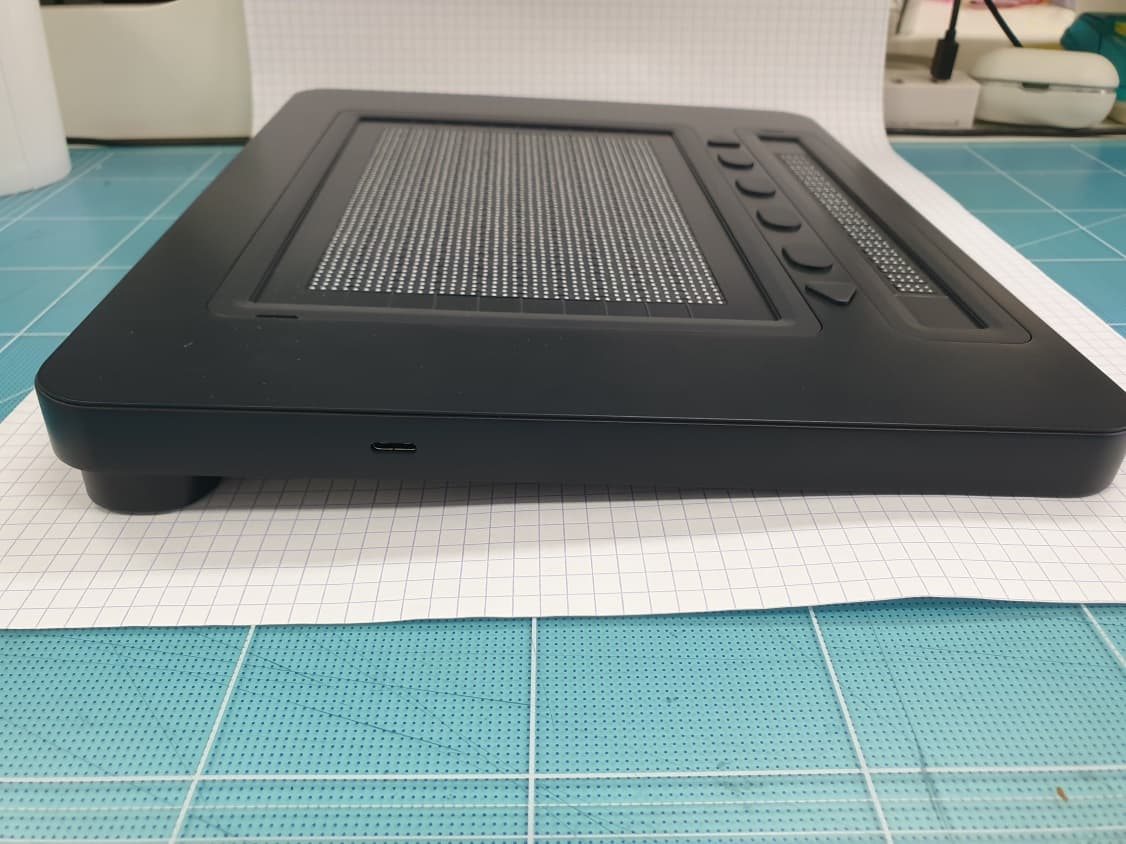
Click to zoom
Application Details
- Equipment Class
- DTS - Digital Transmission System
- Date of Grant
- Mar 27, 2023
- Application Purpose
- Original Equipment
- Date of Application
- Mar 27, 2023
- Equipment Note
- Refreshable tactile graphic display
- Frequency Range
- 2402.00000000 - 2480.00000000
- Company
- dot incorporation
- Country
- South Korea
Documents & Files
Document Text
Text extracted from the exhibit documents filed with the FCC. Open a document above to read the original.
Users Manual
08591 Gasan Digital 1-Ro2, Geumcheon-gu, Seoul, Kore a 10F No. 1005 (Gasan-dong, Woorim Lions Valley 2nd) Phone Number: +82) 2-864-1113 Fax: +82) 2-864-1989 Email: [email protected] m Homepage: www.dotincorp.com Dot Pad 320 (DPA320A) User Guide Dot Incorporation DPA320 User Guide Dot Incorporation www.dotincorp.com Proprietary & Confidential Information Table of Contents 1. Dot Pad 320 1.1. What is the Dot Pad 320? 1.2. Components of Dot Pad 320 1.3. Dot Pad 320 Appearance 1.3.1 Dot Pad 320 Top 1.3.2. Dot Pad 320 Right Side 1.3.3. Dot Pad 320 Left Side 1.3.4. Dot Pad 320 Floor Surface 1.4. Hardware Specifications 1.5. Software Specifications 2. Basic Functions 2.1. Checking the Dot Pad 320 Cell Operation 2.2. Understanding device information through Dot Pad 320 vibration signals 2.3. Checking the battery level 3. Connecting the Dot Pad 320 to iPhone and iPad 3.1. Disconnecting the Dot Pad 320 4. Connecting the iPhone/iPad with the Dot Pad 320 to read tactile images and braille 4.1. Reading Text Braille 4.2. Displaying the Image (Default) 4.3. Reading images in detail with rotors 4.3.1. Adding Image Navigation Options to the Rotor 4.3.2. Using Image Inversion 4.3.3. Enlarging an Image 4.3.4. Scrolling Images Horizontally and Vertically 4.3.5. Adjusting the Image Line Thickness 4.4. Viewing Images Using Voiceover Recognition 4.4.1. Creating Image Recognition Gestures 4.4.2. Using the Image Recognition Function to Check an Image 5. Viewing Images (Advanced Features) 5.1. Viewing Photo Gallery Images 5.2. Viewing Images in the Camera Viewfinder 5.3. Viewing Images on a Web Page 6. Customizing the Dot Pad 320 Keys 7. Handling and Safety Precautions 8. Customer Support 8.1. Dot Email 8.2. Dot Phone Number 8.3. Dot Homepage 9. Product Certifications DPA320 User Guide Dot Incorporation www.dotincorp.com Proprietary & Confidential Information 1. About Dot Pad 320 (DPA320A) 1.1. What is the Dot Pad 320? The Dot Pad 320 is a display that can simultaneously represent Braille text and tactile graphics. You can connect to and use your iPhone & iPad with OS 15.2 or above installed. When you connect to your iPhone and iPad, you can print the pictures, photos, and icon shapes that appear on the screen as tactile information to the Dot Pad 320 in real-time. Alternatively, you can use a dedicated SDK released by Dot to output tactile information from specific applications to the Dot Pad 320. 1.2. Components of Dot Pad 320 When you purchase a Dot Pad 320, it includes the following components: Configuration and Support Body and battery 1 Quick Guide (Braille) 1 Dot Pad Case 1 USB cable 1 Warranty Period 1 year 1.3. Dot Pad 320 Appearance When the Dot Pad 320 is removed from the box and placed on the desk, the square body is slightly inclined towards the side of the body and is in the correct position. The side closer to the body (the lower slope) is the front, and the farthest side from the body (the highest side) is the rear. The main areas that control the devices in the Dot Pad 320 and output braille are located on the top right sides, on the left side, and on the bottom plane. Therefore, this manual provides guidance on the top and right sides, the left side, and the bottom surface controls. DPA320 User Guide Dot Incorporation www.dotincorp.com Proprietary & Confidential Information 1.3.1 Dot Pad 320 Top view When the Dot Pad 320 is normally placed , the upper surface of the Dot Pad 320 is divided into the following parts from nearest to farthest from the body: - Braille text display area. - The keyboard area where the panning and function keys are gathered. - The graphic area where the tactile graphic is displayed. The Braille text display area serves as the braille output of a typical braille information terminal; it consists of 20 cells in a long horizontally rectangular frame, arranged at standard braille spacing. Thus, 20 alphabetic characters can be represented at the same time. Starting from the left to the right, the keyboard area consists of the previous panning key, keys F1 through F4 , and the next panning key. The shape of the panning keys is a triangle, which distinguishes them from other Function keys which are in an oval shape. ● Note: A panning key is a key that moves to the previous and next line along the braille cells. The Function key can be used to connect with the voiceover. The key operation method is as follows (description in the brackets are the actions taken on your device to achieve the same results): - F1: Moves from the currently focused object to the previous one. (Swipe one finger to the left) - F2: Go to Home. - F3: Executes the currently focused object. (Double-tap with one finger) - F4: Moves from the currently focused object to the next object. (One finger right swipe) DPA320 User Guide Dot Incorporation www.dotincorp.com Proprietary & Confidential Information The rightmost part of the keyboard area is the LED area. Bluetooth (blue) Charging (red) Flashing Pending connection LED off Charging off LED on Connected Flashing Charging error LED on Charging Braille Graphics information terminal is the area occupying the largest space and is the area for outputting tactile graphics. The cells more densely populated than the braille cells can be used to output images that appear on iPhone and iPad screens in real time. Alternatively, tactile graphic content can be displayed from a dedicated application that supports Dot Pad 320. A cell in the tactile graphics area consists of 300 cells (30 wide by 10 vertical) with 8-point pins. All the pins are placed in equal intervals up and down, left and right, for sophisticated graphical representation. 1.3.2. Dot Pad 320 Right Side On the right side of the Dot Pad 320, starting from the rear to the front, there is a USB C type power charging port, followed by a power switch. A USB C type power port is a power only port. Keep in mind that there is no data transfer. The power switch powers on when pushed up to the far side of the body.…
Text truncated - open the document above for the full version.
Attestation Statements
dot incorporation 1005, 2, Gasan digital 1-ro, Geumcheon-gu, Seoul, Republic of Korea Tel. +82-2- 864-1113 / Fax +82-2- 864-1989 Federal Communications Commission Authorization and Evaluation Division 7435 Oakland Mills Road Columbia, MD 21046 USA Date: 03-14-2023 Ref: Attestation Statements Part 2.911(d)(5)(i) Filing FCC ID: 2BAM7DPA320A dot incorporation certifies that the equipment for which authorization is sought is not “covered” equipment prohibited from receiving an equipment authorization pursuant to section 2.903 of the FCC rules. Best Regards, Sang Hyun Lee / CTO dot incoporation Rev 1/26/2023 dot incorporation (Ace Highend Tower 7th 2002), 67, Gasan digital 2-ro, Geumcheon-gu, Seoul, South Korea Tel. +82-2- 864-1113 / Fax +82-2- 864-1989 Federal Communications Commission Authorization and Evaluation Division 7435 Oakland Mills Road Columbia, MD 21046 USA Date: 03-14-2023 Ref: Attestation Statements Part 2.911(d)(5)(ii) Filing FCC ID: 2BAM7DPA320A dot incorporation certifies that, as of the date of the filing of the application, the applicant is not identified on the Covered List as an entity producing “covered” equipment. Best Regards, Sang Hyun Lee / CTO dot incoporation Rev 1/26/2023
Attestation Statements
dot incorporation 1005, 2, Gasan digital 1-ro, Geumcheon-gu, Seoul, Republic of Korea Federal Communications Commission Authorization and Evaluation Division 7435 Oakland Mills Road Columbia, MD 21046 USA Date: 03-23-2023 Ref: Attestation Statements Part 2.911(d)(7) Filing FCC ID or Grantee Code: 2BAM7DPA320A [dot incorporation]certifies that, as of the date of the filing of the application, [FCC US Agent, LLC] is our designated U.S. agent for service of process for the above referenced FCC ID. [dot incorporation] accepts to maintain an agent for no less than one year after the grantee has terminated all marketing and importation or the conclusion of any Commission-related proceeding involving the equipment. [FCC US Agent, LLC] accepts, as of the date of the filing of the application, the obligation of the designated U.S. agent for service of process for the above referenced FCC ID. Designated U.S. Agent Information: Name: FCC US Agent, LLC FRN: 0033402884 Address: 3722 Illinois Avenue, Saint Charles, IL, 60174, USA Contact Person: Tim Payne Email: [email protected] Sincerely, dot incorporation FCC US Agent, LLC Sang Hyun Lee Tim Payne Signature Signature
Cover Letter(s)
dot incorporation 1005, 2, Gasan digital 1-ro, Geumcheon-gu, Seoul, Republic of Korea Tel. +82-2-864-1113 / Fax +82-2-864-1989 March 23, 2023 Federal Communications Commission Equipment Authorization Branch 7435 Oakland Mills Road Columbia, MD 21046 In re : dot incorporation FCC Application for FCC ID : 2BAM7DPA320A To whom it may concern: We, the undersigned, hereby attest to the fact that we will apply the Supplier’s Declaration of Conformity procedure to the class B computer peripheral portion of this composite filing. Best Regards, Sang Hyun Lee / CTO dot incoporation
Cover Letter(s)
dot incorporation 1005, 2, Gasan digital 1-ro, Geumcheon-gu, Seoul, Republic of Korea Te l . + 8 2-2-864-1113 / Fax +82-2-864-1989 March 23, 2023 Federal Communications Commission Equipment Authorization Branch 7435 Oakland Mills Road Columbia, MD 21046 In re : dot incorporation FCC ID : 2BAM7DPA320A Request for Confidentiality Pursuant to Sections 0.457 and 0.459 of the Commission’s Rules (CFR 47), dot incorporation hereby requests confidentiality and treatment of certain information accompanying this application. The materials contain trade secrets and proprietary information not customarily released to the public. The public disclosure of these matters might be harmful to the Applicant and provide unjustified benefits to its competitors. We are also hereby request Short-Term Confidentiality for 180 days after the grant as outlined in Public Notice DA 04-1705. This provision will give dot incorporation temporary confidentiality of commercially sensitive information prior to product release. The requested Confidential and Temporary Confidential exhibits are listed as follows: Exhibit Type File Name CONFIDENTIAL Schematics CONF APPENDIX 2BAM7DPA320A SCH DIA.pdf Parts list CONF APPENDIX 2BAM7DPA320A PL.pdf Block diagram CONF APPENDIX 2BAM7DPA320A BLK DIA.pdf Operational description CONF APPENDIX 2BAM7DPA320A OpDes.pdf SHORT-TERM CONFIDENTIAL External Photos SHORT-TERM CONF 2BAM7DPA320AEXT Photo.pdf Internal Photos SHORT-TERM CONF 2BAM7DPA320A INT Photo.pdf Te s t-Setup Photos SHORT-TERM CONF 2BAM7DPA320A Test Photo.pdf User’s Manual SHORT-TERM CONF 2BAM7DPA320A Manual.pdf The Applicant understands that pursuant to Rule 0.457, disclosure of this application and all accompanying documentations, where applicable, will not be made public before the date of the Grant for this application. Best Regards, Sang Hyun Lee / CTO dot incoporation
Cover Letter(s)
dot incorporation 1005, 2, Gasan digital 1-ro, Geumcheon-gu, Seoul, Republic of Korea Tel. +82-2-864-1113 / Fax +82-2-864-1989 March 23, 2023 Federal Communications Commission Equipment Authorization Branch 7435 Oakland Mills Road Columbia, MD 21046 LETTER OF AUTHORIZATION To whom it may concern: We, the undersigned, hereby authorize LTA Co., Ltd., to act on our behalf in all manners relating to application for equipment authorization for FCC ID: 2BAM7DPA320A including signing of all documents relating to these matters. Any and all acts carried out by LTA Co., Ltd., on our behalf shall have the same affect as acts of our own. This authorization is valid until further written notice from dot incorporation LTA Co.,LTD. (Contact Person) Contact name: Ja-Beom Koo Position: Manager Phone:(82)31-323-6008 E-mail: [email protected] Best Regards, Sang Hyun Lee / CTO dot incoporation
External Photos
FCC ID: 2BAM7DPA320A Front Rear Copyright ○ c 2023, LTA Co., Ltd .Page 1 of 5 FCC ID: 2BAM7DPA320A Side Side Copyright ○ c 2023, LTA Co., Ltd .Page 2 of 5 FCC ID: 2BAM7DPA320A Side Side Copyright ○ c 2023, LTA Co., Ltd .Page 3 of 5 FCC ID: 2BAM7DPA320A ANTENNA(2.4 GHz) Copyright ○ c 2023, LTA Co., Ltd .Page 4 of 5 FCC ID: 2BAM7DPA320A Label Position Copyright ○ c 2023, LTA Co., Ltd .Page 5 of 5
ID Label/Location Info
FCC ID: 2BAM7DPA320A SAMPLE LABEL & LOCATION EUT Rear position dot incorporation Model : DPA320A Rated Voltage : DC 3.7 V FCC ID : 2BAM7DPA320A Contains Modules : A8TBM70ABCDEFGH Made in Korea Copyright Ⓒ 2023, LTA Co., Ltd.
Internal Photos
FCC ID: 2BAM7DPA320A Main Board Front Main Board Rear Copyright ○ c 2023, LTA Co., Ltd. Page 1 of 3 FCC ID: 2BAM7DPA320A Board Front Board Rear Copyright ○ c 2023, LTA Co., Ltd. Page 2 of 3 FCC ID: 2BAM7DPA320A Internal Copyright ○ c 2023, LTA Co., Ltd. Page 3 of 3
RF Exposure Info
FCC ID: 2BAM7DPA320A ATTACHMENT RF EXPOSURE EVULATION 1.1 Limit According to §1.1310 and §2.1091 RF exposure is calculated. (B) Limits for General Population/Uncontrolled Exposures Frequency range (MHz) Electric field Strength Magnetic field Strength Power density Averaging time 1.34 - 30....................................... 824/f 2.19/f *(180/ f²) 30 30 - 300....................................... 27.5 0.073 0.2 30 300 - 1500.................................... ............... ............... f/1500 30 1500 - 100.000................................. ............... ............... 1.0 30 F = frequency in MHz * = Plane-wave equivalent power density 1.2 MAXIMUM PERMISSIBLE EXPOSURE Prediction Prediction of MPE limit at a given distance Power density at the specific separation: S = PG/(4R 2 π) Where, S = Maximum power density (mW/cm 2 ) P = Power input to the antenna (mW) G = Numeric power gain of the antenna R = Distance to the center of the radiation of the antenna (20 cm = limit for MPE) S = (1.34 *1.46) / (4 * 5 2 * π) S = 0.65 mW/cm 2 FCC ID: 2BAM7DPA320A ATTACHMENT 1.3 MAXIMUM PERMISSIBLE EXPOSURE Prediction - Calculated under the worst-case conditions of each mode. (Measured power 1.5 dBm ± 0.5dB) 3-1. 2.4 GHz Mode Max Peak output Power at antenna input terminal 1.46 dBm Max Peak output Power at antenna input terminal 1.4 mW Prediction distance 5 mm Prediction frequency 2,402 MHz Antenna Gain(typical) 1.63 dBi Antenna Gain(numeric) 1.46 - Power density at prediction frequency( S) 0.65 mW/cm 2 MPE limit for uncontrolled exposure at prediction frequency 0.325 mW/cm 2 SAR Test exclusion thresholds for 100MHz to 6GHz at test separation distance ≤ 50 mm = Used [(max.power of channel, including tune-up torelance, mW)/(min. test separation distance, mm)] * [√f(GHz)] = [1.4 / 5 ] * [ √2.402 ] = 0.04 ≤ 3.0, for 1g SAR Thus, SAR for this device is not required.
Test Report
Ref. No.: LR500112011R 243 Jubug-Ri,Yangji-Myeon, Yongin-Si, Gyeonggi-Do, Korea 17159 Tel: +82-31-323-6008 Fax: +82-31-323-6010 http://www.ltalab.com Dates of Tests: February 07,2023 ~ February 24,2023 Test Report S/N: LR500112011R Test Site : LTA CO., LTD. CERTIFICATION OF COMPLIANCE FCC ID. APPLICANT Equipment Class : Digital Transmission System (DTS) Manufacturing Description : Refreshable tactile graphic display Manufacturer : dot incorporation Model name : DPA320A Contains Modules : A8TBM70ABCDEFGH Test Device Serial No.: : Identical prototype Rule Part(s) : FCC Part 15.247 Subpart C ; ANSI C63.10 - 2013 Frequency Range : BLE 2402 ~ 2480 MHz Max. Output Power : 0.0014 W Data of issue : February 27, 2023 This test report is issued under the authority of: The test was supervised by: Ja -Beom Koo, Manager Eun-Hwan Jung, Test Engineer This test result only responds to the tested sample. It is not allowed to copy this report even partly without the allow ance of the test laboratory. The report must not be used by the client to claim product certification, approval, or endorsement by NVLAP, NIST, or any agency of the Federal Government. NVLAP LAB Code.: 200723-0 2BAM7DPA320A dot incorporation Copyright ○ c 2023, LTA Co., Ltd. Page 1 of 13 Ref. No.: LR500112011R TABLE OF CONTENTS 1. GENERAL INFORMATION -------------------------------------------------------------------------- 2. INFORMATION ABOUT TEST ITEM ------------------------------------------------------------- 3. TEST REPORT ------------------------------------------------------------------------------------------ 3.1 SUMMARY OF TESTS ---------------------------------------------------------------------------- 3.2 TECHNICAL CHARACTERISTICS TEST ---------------------------------------------------- 3.2.1 RADIATED SPURIOUS EMISSIONS------------------------------------------------------------ APPENDIX APPENDIX TEST EQUIPMENT USED FOR TESTS -------------------------------------------- 3 4 5 5 6 6 13 Copyright ○ c 2023, LTA Co., Ltd. Page 2 of 13 Ref. No.: LR500112011R 1. General information 1- 1 Test Performed Company name : LTA Co., Ltd. Address : 243, Jubug-ri,Yangji-Myeon,Youngin-Si, Kyunggi-Do, Korea. 17159 Web site : http://www.ltalab.com E-mail : [email protected] Telephone : +82-31-323-6008 Facsimile +82-31-323-6010 Quality control in the testing laboratory is implemented as per ISO/IEC 17025 which is the “General requirements for the competents of calibration and testing laboratory”. 1- 2 Accredited agencies LTA Co., Ltd. is approved to perform EMC testing by the following agencies: Agency Country Accreditation No. Validity Reference NVLAP U.S.A 200723-0 2023-09-28 ECT accredited Lab. RRA KOREA KR0049 - EMC accredited Lab. FCC U.S.A 649054 Updating FCC CAB VCCI JAPA N C-4948, 2023-09-10 VCCI registration VCCI J APA N T-2416, 2023-09-10 VCCI registration VCCI J APA N R-4483(10 m), 2023-08-15 VCCI registration VCCI J APA N G-847 2023-12-13 VCCI registration IC CANADA 5799A-1 2023-10-18 IC filing Copyright ○ c 2023, LTA Co., Ltd. Page 3 of 13 Ref. No.: LR500112011R 2. Information about test item 2-1 Client & Manufacturer Client Company name : dot incorporation Address : 1005, 2, Gasan digital 1-ro, Geumcheon-gu, Seoul, Republic of Korea Tel / Fax : TEL No : +82-2-864-1113 / FAX No : + 82-2-864-1989 Manufacturer dot incorporation Address 1005, 2, Gasan digital 1-ro, Geumcheon-gu, Seoul, Republic of Korea Tel / Fax TEL No : +82-2-864-1113 / FAX No : + 82-2-864-1989 2- 2 Equipment Under Test (EUT) Model name : 2BAM7DPA320A Serial number : Identical prototype Date of receipt : February 07, 2023 EUT condition : Pre-production, not damaged Antenna type : Chip Antenna (Max Gain : 1.63 dBi) Frequency Range : BLE 2402 ~ 2480 MHz Type of Modulation : GFSK Power Source : DC 3.7 V 2- 3 Tested frequency LOW MID HIGH Frequency (MHz) BLE 2402 2442 2480 2-4 Ancillary Equipment Equipment Model No. Serial No. Manufacturer - - - - Copyright ○ c 2023, LTA Co., Ltd. Page 4 of 13 Ref. No.: LR500112011R 3. Test Report 3.1 Summary of tests FCC Part Section(s) Parameter Test Condition Status (note 1) 15.247(a) 6 dB Bandwidth Conducted N/A 1) 15.247(b) Transmitter Peak Output Power N/A 1) 15.247(e) Transmitter Power Spectral Density N/A 1) 15.247(d) Band Edge & Conducted Spurious emission N/A 1) 15.209 Transmitter emission Radiated C 15.207 AC Conducted Emissions Conducted N/A 1) 15.203 Antenna requirement - C N/A 1) : The product replaces this test with a certificate using an authenticated module. The above equipment was tested by LTA Co., Ltd. The test data, data evaluation, test procedures, and equipment configurations shown in this report were made in accordance with the procedures given in ANSI C63.10-2013 and the energy emitted by the sample EUT tested as described in this report is in compliance with the requirements of FCC Rules Part 2 and Part 15.247 The test results of this report relate only to the tested sample identified in this report. The tests were performed according to the method of measurements prescribed in KDB No.558074. Antenna Requirement dot incorporation. FCC ID: 2BAM7DPA320A unit complies with the requirement of §15.203. The antenna type is Chip Antenna Copyright ○ c 2023, LTA Co., Ltd. Page 5 of 13 Ref. No.: LR500112011R 3.2 Technical Characteristics Test 3.2.1 Radiated Spurious Emissions Procedure: Radiated emissions from 30 MHz to 25 GHz were measured according to the methods defines in ANSI C63.10-2013. The EUT is a placed on as turn table. For emissions testing at or below 1 GHz, the table height shall be 0.8 m above the reference ground plane. For emission measurements above 1 GHz, the table height shall be 1.5 m. The turn table shall rotate 360 degrees to determine the position of maximum emission level. EUT is set 3m away from the receiving antenna which varied from 1m to 4m to find out the highest emission. And also, each emission was to be maximized by changing the polarization of receiving antenna both horizontal and ver…
Text truncated - open the document above for the full version.
Test Setup Photos
FCC ID: 2BAM7DPA320A Radiate Emission Copyright ○ c 2023, LTA Co., Ltd. Page 1 of 3 FCC ID: 2BAM7DPA320A Copyright ○ c 2023, LTA Co., Ltd. Page 2 of 3 FCC ID: 2BAM7DPA320A Copyright ○ c 2023, LTA Co., Ltd. Page 3 of 3
Contact Information
Applicant
Sang Hyun Lee(CTO)
Test Firm
LTA Co.,LtdAhn Chulho
Technical Specifications
| # | Rule Parts | Frequency Range | Power Output |
|---|---|---|---|
| 1 | 15C | 2.40 GHz - 2.48 GHz | 1.40 mW |
Other Applications from dot incorporation
2BAM7DPK12A
Oct 02, 2024Portable Braille device for Visually impaired
Equipment Class
DTS - Digital Transmission System