2BAMRF220-2SThe Pertronic F220-2S is a 150W, modular, expandable, networkable, intelligent, addressable, automatic fire alarm system designed for medium to large building applications.
Pertronic Industries Limited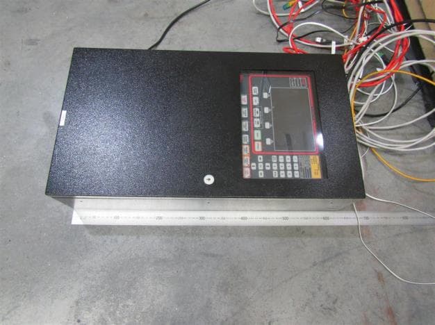
Click to zoom
Application Details
- Equipment Class
- JAD - Part 15 Class A Digital Device
- Date of Grant
- Sep 12, 2024
- Application Purpose
- Original Equipment
- Date of Application
- Sep 12, 2024
- Equipment Note
- The Pertronic F220-2S is a 150W, modular, expandable, networkable, intelligent, addressable, automatic fire alarm system designed for medium to large building applications.
- Company
- Pertronic Industries Limited
- Country
- New Zealand
Documents & Files
Document Text
Text extracted from the exhibit documents filed with the FCC. Open a document above to read the original.
Users Manual
© Pertronic Industries Inc 187 0063 F220 Tech Manual USA v9.04.02 20240530 19.1.6 Mainboard LED Indicator Layout Figure 19-5: F220 Mainboard LED Layout © Pertronic Industries Inc 188 0063 F220 Tech Manual USA v9.04.02 20240530 LED Designator Function LED Color 1 External High-Speed RS-485 TxD Green 2 NAC 1 Active Red 3 NAC 2 Active Red 4 NAC 3 Active Red 5 Trouble Relay On Green 6 Auxiliary Relay On Yellow 7 External High-Speed RS-485 RxD Green 8 Output 3 Relay On Yellow 9 Fire Relay On Red 10 NAC 4 Active Red 11 NA 12 Supervisory Yellow 13 Extension Bus RxD Green 14 Extension Bus TxD Green 15 Isolated RS232 RxD Green 16 Isolated RS232 TxD Green 17 Ground Trouble Yellow 18 Auxiliary Trouble Yellow 19 NA 20 NA 21 NA 22 System Trouble Yellow 23 Internal High-Speed RS-485 TxD Green 24 Internal High-Speed RS-485 RxD Green 25 USB Active Green 26 Output 1 Yellow 27 Output 2 Yellow Table 19-3: LED Indicators © Pertronic Industries Inc 189 0063 F220 Tech Manual USA v9.04.02 20240530 19.1.7 Mainboard External Connections Figure 19-6: F220 Mainboard External Connections © Pertronic Industries Inc 190 0063 F220 Tech Manual USA v9.04.02 20240530 19.1.8 Mainboard NAC Class A and Class B Wiring Figure 19-7: F220 Mainboard NAC Class A and Class B Wiring © Pertronic Industries Inc 191 0063 F220 Tech Manual USA v9.04.02 20240530 19.1.9 Mainboard NAC Wiring Requirements Table 19-4 lists the NAC wiring requirements. NAC Load (A) Maximum Total Allowable Loop Resistance (ohms) Class B Max allowable wire pair’s length (feet) Class A Max allowable wire pair’s length (feet) AWG 12 (Solid) AWG 14 (Solid) AWG 16 (Solid) AWG 18 (Solid) AWG 12 (Solid) AWG 14 (Solid) AWG 16 (Solid) AWG 18 (Solid) 0.5 6.4 1650 1035 650 410 825 518 325 200 1.0 3.2 825 518 325 205 412 259 164 100 1.5 2.1 550 345 220 136 275 173 108 65 2.5 1.6 412 260 163 102 206 129 80 50 Table 19-4 NAC Wiring Distance and Gauge Requirements NOTE: 1.The maximum allowable NAC line resistance is 10 ohms. 2. The distances in Table 19-4 are based on the current draw of the highest candela strobes at the low end of the supported NAC voltage, with the entire load at the end of the circuit. More accurate distances can be determined by performing point-to-point voltage calculations using the specific devices and their distribution along the NAC. © Pertronic Industries Inc 192 0063 F220 Tech Manual USA v9.04.02 20240530 19.2 F220 Keyboard Display 19.2.1 F220 Keyboard Display PCB Connector, Switch and Indicator Layout Figure 19-8: F220 Keyboard Display Connectors and Switch Layout (Reverse) Figure 19-9: F220 Keyboard Display Switches and Indicator Layout (Panel) 19.2.2 F220 Keyboard Display Field Wiring Connectors Connector Designator Connector Description Connector Header/ Plug Connector PCB label Input/ Output Protocol/ Rating/ Signaling Type Wiring size range (AWG) Solid/ (Stranded) Supervised Power Limited Output: Max Frequency Max Current Max Voltage K1 Door Switch Door SW 0V IN - (13-24) Supervised Power limited Not intended for field wiring K2 Not Used Not Used Not Used Not intended for field wiring K3 Serial Data RxD, 0V, TxD I/O 11-24 (13-24) Power limited Not intended for field wiring K4 Internal RS485 + - B A Internal RS485 I/O 11-24 (13-24) Power limited Not intended for field wiring K5 Door Switch 0V Door Switch IN - (13-24) Supervised Power limited Not intended for field wiring K8 Buzzer Silence Buzz SL BCO TE 0V OUT Power limited Not intended for field wiring K9 Aux/Aux Flt I/P Aux, 0V Aux Flt 0V IN - (22-26) Power limited Not intended for field wiring K10 Ground Ground Terminal 12-30 (12-30) Not intended for field wiring K12 Internal RS- 485 + - B A High-Speed RS485 I/O - (22-26) Power limited Not intended for field wiring K13/Plug1 HS RS-485 IN XCFR2 FW2/FW2 + - B A High-Speed RS485 I/O RS-485 and 24 VDC supply 12-22 (12-22) Power limited Panel: Not intended for field wiring Annunciator: field wiring K14/Plug2 HS RS-485 OUT XCFR2 FW2/FW2 + - B A High-Speed RS485 I/O RS-485 and 24 VDC supply 12-22 (12-22) Power limited Panel: Not intended for field wiring Annunciator: Field wiring J1 JTAG JTAG I/O N/A Power limited Not intended for field wiring J2 USB-A I/O N/A Power limited Not intended for field wiring Table 19-5: F220 Keyboard Display Field Wiring © Pertronic Industries Inc 193 0063 F220 Tech Manual USA v9.04.02 20240530 © Pertronic Industries Inc 194 0063 F220 Tech Manual USA v9.04.02 20240530 19.3 SLC Driver Board (F220AP2LDB) 19.3.1 SLC Connector and Switch Layout Figure 19-10: SLC Driver Connector and Switch Layout 19.3.2 SLC Driver LED Indicator Layout Figure 19-11: SLC Driver LED Indicator Layout © Pertronic Industries Inc 195 0063 F220 Tech Manual USA v9.04.02 20240530 19.3.3 Updating SLC (Loop) Driver Firmware The SLC (Loop) Driver firmware can be loaded onto the Driver board using a USB memory stick. The firmware update process does not check the installed firmware version, the uploaded file will always replace the currently loaded firmware. USB memory stick setup: • The USB memory stick must be FAT32 formatted, See 7.4 USB Flash Memory File System Format. • Open the zip file containing the firmware to be installed. The zip file name will be in the format eNet_package_USA_vx.x.x.zip where x is the version numbering. • Copy the entire folder named ‘LD3_Firmware’ into the root directory of the USB stick. SLC (Loop) Driver board firmware upload process: • Plug in the USB driver (K8 on Driver PCB) • Set DIP switch 4 to ON (Green square). This switch is labelled ‘SW’ and is only read at startup. • Press the reset button labelled ‘Reset’. • The Status LED will start to blink quickly (See Figure 19-12 below) • Wait for the USB LED to stay on constantly indicating that upload process was successful. • Switch DIP switch 4 to OFF. • Press the ‘Reset’ button. • Wait a few seconds to ensure the two polling LEDs are flashing. USB LED Activity Notes Slow blink, 0.5s on /0.5s off LD3 is ready for a firmware upload and waiting for a USB memory stick …
Text truncated - open the document above for the full version.
Users Manual
© Pertronic Industries Inc 87 0063 F220 Tech Manual USA v9.04.02 20240530 When the first DDA enabled detector is activated, • the Pre-Alarm event screen is displayed and • the yellow Pre-Alarm indicator will be ON • When the second DDA enabled detector is activated, the Pre- Alarm indicator will turn OFF, • OR, when a detector which is not DDA enabled is activated, the Pre- Alarm indicator will remain ON, • In both cases, the Primary Alarm screen will also be displayed. 8.11 LEDs In Pertronic terminology, the term LED not only refers to the physical light emitting devices on panels and annunciators but also to virtual devices which can be configured to activate functions and events within a F220 Fire Panel or across an F220 network. For example, an output from a Detector, Zone, System Event or Logic Block can be configured to start a timer or trigger a SLC relay. 8.11.1 Implementation in FireUtils Configuring LEDs is accomplished in FireUtils using the various editors Input and/or Output Managers (Refer to Table 8-13 below). The maximum number of LEDs is 2048. Function Input Manager Output Manager SLC - Outputs 1 to 4 Zone - Outputs 1 to 8 Groups - Outputs 1 to 15 © Pertronic Industries Inc 88 0063 F220 Tech Manual USA v9.04.02 20240530 Timers Start, Reset, Disable, Override T1 Outputs 1,2; T2 Outputs 1,2 System Events - Outputs 1 to 6 Logic Blocks Inputs 1 to 8 Outputs 1 to 4 Table 8-13: Configuring LED Inputs and Outputs Figure 8-23: LED I/O Trace 8.12 Auxiliary Outputs Eight configurable auxiliary outputs are available for internal panel use only; they are not field wire connections. These outputs are available on connector K35, located on the right-hand edge of the F220 Mainboard (refer to Figure 19-1). Each output uses a current sink driver rated at 100 mA (8 drivers at 100% duty cycle). 8.12.1 Implementation in FireUtils In FireUtils, Auxiliary Outputs are configured through accessing the Output Managers of SLC, Zone, Group, System Events, Timer and Logic Blocks Editors. They are also mapped to Input Managers of Timer, System Events and Logic Block. As no mapping can be configured in the Auxiliary Output Editor, its primary function is for displaying which outputs are driving which Aux Output. © Pertronic Industries Inc 89 0063 F220 Tech Manual USA v9.04.02 20240530 Figure 8-24: Auxiliary Output I/O Trace 8.13 Supervisory Signals The F220 can monitor input signals that relate to an abnormal status (other than a Trouble) from other systems that are attached and monitored by the fire alarm system such as sprinkler valves, CO devices, and pressure switches. These signals are identified as ‘Supervisory’ by setting the Supervisory Flag for the modules associated with the signal input. Supervisory signals are handled within the Supervisory queue where they can be viewed (Menu > 2. History Logs > 4. Supervisory Log). Whenever a supervisory signal is present the Supervisory LED will FLASH, and the buzzer will sound. If this event is currently the highest priority, the Supervisory screen will also be displayed. 8.13.1 Viewing and Resetting Supervisory Signals If there are current Supervisory events available for viewing these will be displayed in the Supervisory Events list providing these are the highest priority current events. If this is not the case press the OK key repeatedly until the ‘Supervisory Events’ screen appears. A latched Supervisory signal must be manually reset at the panel. To reset latched Supervisory events, select the event using the up or down arrow keys and then press ‘Reset’. © Pertronic Industries Inc 90 0063 F220 Tech Manual USA v9.04.02 20240530 8.13.2 Supervisory Signal Log Historic Supervisory Signal events can be viewed within the Supervisory Log—option 4 in the History Log menu. This log can contain up to 500 events and the oldest events will be overwritten with the latest events when this capacity is exceeded (Refer to Section 2.2.6). © Pertronic Industries Inc 91 0063 F220 Tech Manual USA v9.04.02 20240530 9. OPERATING THE EMERGENCY RESPONSE FACILITY NOTE: For information on the controls and indicators of the F220 front panel, and the System Panel in particular, refer to Section 2: F220 Front Panel Controls and Display The Fire Panel highlights, and provides key controls, to enable an alarm to be satisfactorily dealt with by fire fighters or emergency response providers. For reference, the layout of the Fire Panel is shown below. Figure 9-1: The Emergency Response window on the Front Panel 9.1 Responding to a Fire Alarm The following diagrams are examples of the indicators, switches and screens that a fire fighter or emergency response provider may access on the F220, once on site, to determine the location and extent of the fire, and finally reset the system. © Pertronic Industries Inc 92 0063 F220 Tech Manual USA v9.04.02 20240530 Figure 9-2: Responding to a Fire Alarm © Pertronic Industries Inc 93 0063 F220 Tech Manual USA v9.04.02 20240530 Figure 9-3: Responding and Acknowledging a Fire Alarm © Pertronic Industries Inc 94 0063 F220 Tech Manual USA v9.04.02 20240530 10. OPERATING THE USER MENU The F220 can be configured using the Keyboard-Display and selecting the appropriate items from the following menu tree. Figure 10-1: F220 User Menu Tree © Pertronic Industries Inc 95 0063 F220 Tech Manual USA v9.04.02 20240530 NOTE: The first, or top, level of the ‘User Menu’ can be reached by pressing the ‘Menu’ key on the front panel (Menu>) Items in the ‘User Menu’ can be selected by pressing either the numeric keys, or by moving the selection highlight using the arrow keys, then pressing ‘OK’. User Menu > Press ‘Esc/Back’ to move back to a higher level in the ‘User Menu’ tree 10.1 User Menu - Disablement menu (Menu option 1) Press Disablement Menu in the User Menu User Menu> Disablement Menu Press the corresponding numeric key to select the Disablement type required. 10.1.1 Disable Zones (Menu option 1.1) In the Disablement Menu, select Disable Zones User Menu>D…
Text truncated - open the document above for the full version.
Users Manual
0063 F220 Tech Manual USA v9.04.02 20240530 The content of this manual is copyrighted. This document is to be used only for operating or maintaining Pertronic Fire Alarm systems. This document is not to be reproduced, photocopied or passed in part or whole to a third party without the express, written authorization of Pertronic Industries Inc PERTRONIC F220 (F220-2S and F220-2L) AUTOMATIC FIRE ALARM TECHNICAL MANUAL UNITED STATES ISSUE 1.04 © Pertronic Industries Inc ii 0063 F220 Tech Manual USA v9.04.02 20240530 Abbreviations and Definitions: ACK Acknowledge Panel keyswitch used to acknowledge an off-normal situation such as an alarm, pre-alarm, trouble, supervisory or active event. ‘Acknowledge’ keypresses are recorded in the Main Log. Activated Not in its normal state AHJ Authority Having Jurisdiction The organization, office, or individual responsible for enforcing the requirements of the code or standard, or for approving equipment, materials, an installation, or a procedure. NFPA 72-2019 3.2.2 AVF Alarm Verification Feature A feature designed to minimize ‘false alarms’ by ensuring multiple operation of devices (smoke detectors) before the alarm is raised. DDA, AVF and PAS are mutually exclusive. DDA Dual Detector Alarm Available to detectors only. If set, when a detector is activated, the panel will go into a prealarm state. If a second DDA detector is activated, the panel will go into alarm. The default flag setting is ‘Not Set’. DDA, AVF and PAS are mutually exclusive. EOL End of Line End of Line termination, nominally 10kΩ Resistor, used to monitor the presence and integrity of the detector circuit. FACP Fire Alarm Control Panel The main fire alarm system component, provided with primary and secondary power sources that monitors equipment and circuits, receives input signals from initiating devices, activates notification appliances and transmits signals off-site. Also referred to as a FACU Fire Alarm Control Unit. F220 Generic Pertronic fire panel identifier. Specific panel/model numbers are located in Table 23-1: Pertronic Panels Group A software defined collection of SLC devices, zones, and system events HPHO High Sensitivity Photoelectric/ Optical Detector IA Intelligent Addressable Previously called analog addressable Latched A state that is maintained once invoked Removal of the cause and a reset is required to remove a latched state LCD Liquid Crystal Display LED Light Emitting Diode LED addressing LED addressing Historically in Pertronic systems, a Boolean addressing scheme has been used to control the state (ON/OFF) of indicator LEDs in LED Annunciators. This scheme has been extended to include “virtual” LEDs as an output option for SLC devices, Zones, Groups, Timers, System Events, Logic Blocks, etc. which can be configured or mapped to activate shared functions and events within a F220 panel and trigger reactive behavior across a F220 network. MPS Manual Pull Station NAC Notification Appliance Circuit A circuit in which the FACP can communicate to notification appliances such as strobes, bells, horns, and loudspeakers © Pertronic Industries Inc iii 0063 F220 Tech Manual USA v9.04.02 20240530 NC Normally closed Relay or switch contacts NO Normally Open Relay or switch contacts OC Open Circuit PAS Positive Alarm Sequence A fire panel option that delays the notification of a fire (fire department, alarm notification devices etc.) so that suitably trained personnel have time to investigate the cause of the alarm. The alarm must be acknowledged within 15 seconds and, once acknowledged, up to 180 seconds to investigate the alarm. PAS, AVF and DDA are mutually exclusive. PCB Printed Circuit Board Photo Photoelectric optical detector PTIR Photo Thermal Infrared Detector SC Short Circuit SLC Signaling Line Circuit A circuit in which a FACP can communicate to addressable input and output devices, modules, annunciators, interfaces, control units and transmitters. SLC Zone A circuit, typically, in a designated area of a protected building, that when an alarm or trouble occurs will trigger a programmed response in the FACP. Detectors and modules can be assigned to one zone only. IMPORTANT NOTE: This equipment has been tested and found to comply with the limits for a Class A digital device, pursuant to part 15 of the FCC Rules. These limits are designed to provide reasonable protection against harmful interference when the equipment is operated in a commercial environment. This equipment generates, uses, and can radiate radio frequency energy and, if not installed and used in accordance with the instruction manual, may cause harmful interference to radio communications. Operation of this equipment in a residential area is likely to cause harmful interference in which case the user will be required to correct the interference at his own expense. Warning: Any changes or modifications not expressively approved by the grantee could void the user’s authority to operate this equipment. As a F220 system can be provided with optional accessories, the system that was tested and approved was the largest system possible. © Pertronic Industries Inc iv 0063 F220 Tech Manual USA v9.04.02 20240530 CONTENTS 1. Introduction 1 1.1 Functional Description 1 1.2 Overview of Features 3 1.3 Specifications 5 1.4 Capacity 9 2. F220 Front Panel Controls and Display 11 2.1 Fire Alarm Panel 11 2.2 Alphanumeric LCD Display and Menu Functions 11 2.3 Engineering Indicators and Controls 19 3. System Startup and System Self-Tests 23 3.1 System Initialization 23 3.2 Normal Operation System Tests 23 4. Intelligent Addressable Initiating SLCs 24 4.1 SLC Driver 26 4.2 SLC Design 26 4.3 Detectors 28 4.4 Virtual Detectors 30 4.5 Trouble Isolation between Zones 32 4.6 Manual Pull Stations 33 4.7 Monitor Modules 33 4.8 SLC Input Device Parameter Default Settings 35 4.9 SLC Relays 36 4.10 Intelligent Addressable Communications Protocol 37 5. Serial Communication: RS-485 38 5.1 External High-Speed RS-485 Bus 38 5.2 Internal…
Text truncated - open the document above for the full version.
Attestation Statements
PERTRONIC INDUSTRIES LTD Advanced Automatic Fire Detection Systems - Design and Manufacture Mnrt Federal Communications Commission Authorization and Evaluation Division Date: Aug-26-2024 Ref: Attestation Statements Par12.911(dxs)(ii) Filing FCC lD: 2BAMRF220-2S Peftronic Industries Limited 17 Eastern Hutt Rd Wingate P.O. Box 35-063 Naenae 5041 WELLINGTON Telephone: +644567-3229 httos : //oerkonic.co. nz NZBN: 9429040846637 John Brook of Pertronic lndustries Limited ("the applicant") certifies that, as of the date of the filing of the application, the applicant is not identified on the Covered List as a specifically named entity or any of its subsidiaries or affiliates as an entity producing "covered" equipment. Sincerely John Brook
Cover Letter(s)
Advanced Automatic Fire Detection Systems - Design and Manufacture Federal Comm unications Comm ission Authorization and Evaluation Division Date: Aug-26-2024 SUBJECT: FCC Application for FCC lD: 2BAMRF220-2S Peftronic Industries Limited 17 Eastern Hutt Rd Wingate P.0. Box 35-063 Naenae 5041 WELTTNGTON Telephone: +64 4 567-3229 hftos : //pertronic,co.nz NZEN: 9429040846637 To Whom lt May Concern: We, the undersigned, hereby authorize Shabbir Ahmed at EMC Technologies Pty Ltd to act on our behalf, to apply to the Federal Communications Commission for FCC approval of our equipment. Any and all acts carried out by Shabbir Ahmed at EMC Technologies on our behalf shall have the same effect as acts of our own. This is to advise that we are in full compliance with the Anti- Drug Abuse Act. We, the applicant, are not subject to a denial of federal benefits pursuant to Section 5301 of the Anti-Drug Act of 1988, 21 USC853a, and no party to the application is subject to a denial of federal benefits pursuant to that section. Regards, John Brook
Cover Letter(s)
EMC Technologies Pty. Ltd. ABN 82 057 105 549 Melbourne 176 Harrick Road Keilor Park, Vic 3042 Tel: +61 3 9365 1000 Sydney Unit 3/87 Station Road Seven Hills, NSW 2147 Tel: +61 2 9624 2777 Email: [email protected] Web: www.emctech.com.au EMC Technologies Pty Ltd, 176 Harrick Road, Keilor Park VIC 3042 Australia www.emctech.com.au To Federal Communications Commission Attention: Certification Officer EMCT Ref: M2408004 Date: September 2, 2024 Subject: Pertronic Industries Limited Request for Original Certification - FCC ID:2BAMRF220-2S Product Name: F220 Pertronic Fire Alarm System Model: F220-2S FCC ID: 2BAMRF220-2S Operating frequency: The highest frequency generated or used in the device or on which the device operates or tunes as specified by Pertronics Industries is 456 MHz. Description: (supplied by customer) The Pertronic F220 is a modular, expandable, intelligent addressable, automatic fire alarm system designed for medium to large building applications. Please Note: Permanent Confidentiality: Application includes request for permanent confidentiality – Operational Description, Schematics Short-Term Confidentiality: Application does not include request for short-term confidentiality Agent: EMC Technologies is acting as agent for Pertronic Industries Limited in this application. Regards _____________ Shabbir Ahmed CEO EMC Technologies Pty Ltd 176 Harrick Road, Keilor Park, VIC 3042 Australia Ph: +61 3 9365 1000 www.emctech.com.au
External Photos
Page 1 of 9 EMC ENGINEERS & LABORATORIES EMC Bayswater Pty Ltd 18/88 Merrindale Drive Croydon South, Victoria, 3136, Australia Telephone: +61 3 9761 5888 Facsimile: +61 3 8761 6547 Email: [email protected] ABN: 49 112 221 333 Photograph Annex A: External EUT Photographs Pertronic Industries Limited F220-2S Fire Alarm Panel F220-FFANN Local Annunciator NET2-FFANN NET2 Annunciator MPS-PI Pull Station F220 Pertronic Fire Alarm System REPORT: E2405-1792-1 Annex A DATE: September, 2024 EMC Bayswater Test Report E2405-1792-1 Annex A Page 2 of 9 This document may not be reproduced, except in full, without written approval from EMC Bayswater Pty Ltd. Photographs Number Photograph Description 1 EUT – F220-2S Alarm Panel – External views 2 3 4 5 6 7 8 9 10 EUT – MPS-PI Pull Station – External views 11 12 13 14 15 16 17 18 19 EUT – NET2-FFANN (NET2 Annunciator) – External views 20 21 22 23 24 25 26 27 28 EUT – F220-FFANN (Local Annunciator) – External views 29 30 31 32 33 34 35 36 37 Support Equipment – System Sensor P4RL Sounder+Strober NAC1 Device – External views 38 39 Support Equipment – 7351 Detector – External views 40 41 42 Support Equipment – M501MAP Module – External views EMC Bayswater Test Report E2405-1792-1 Annex A Page 3 of 9 This document may not be reproduced, except in full, without written approval from EMC Bayswater Pty Ltd. Photograph 1 Photograph 2 Photograph 3 Photograph 4 Photograph 5 Photograph 6 EMC Bayswater Test Report E2405-1792-1 Annex A Page 4 of 9 This document may not be reproduced, except in full, without written approval from EMC Bayswater Pty Ltd. Photograph 7 Photograph 8 Photograph 9 Photograph 10 Photograph 11 Photograph 12 EMC Bayswater Test Report E2405-1792-1 Annex A Page 5 of 9 This document may not be reproduced, except in full, without written approval from EMC Bayswater Pty Ltd. Photograph 13 Photograph 14 Photograph 15 Photograph 16 Photograph 17 Photograph 18 EMC Bayswater Test Report E2405-1792-1 Annex A Page 6 of 9 This document may not be reproduced, except in full, without written approval from EMC Bayswater Pty Ltd. Photograph 19 Photograph 20 Photograph 21 Photograph 22 Photograph 23 Photograph 24 EMC Bayswater Test Report E2405-1792-1 Annex A Page 7 of 9 This document may not be reproduced, except in full, without written approval from EMC Bayswater Pty Ltd. Photograph 25 Photograph 26 Photograph 27 Photograph 28 Photograph 29 Photograph 30 EMC Bayswater Test Report E2405-1792-1 Annex A Page 8 of 9 This document may not be reproduced, except in full, without written approval from EMC Bayswater Pty Ltd. Photograph 31 Photograph 32 Photograph 33 Photograph 34 Photograph 35 Photograph 36 EMC Bayswater Test Report E2405-1792-1 Annex A Page 9 of 9 This document may not be reproduced, except in full, without written approval from EMC Bayswater Pty Ltd. Photograph 37 Photograph 38 Photograph 39 Photograph 40 Photograph 41 Photograph 42
ID Label/Location Info
© Pertronic Industries Limited 33 F220-2S_F220-2L FCC Class A Test Plan V1.3.docx 6. EUT SYSTEM LABELS 6.1. Label Graphics The following label graphics are draft. Figure 2. F220-2S factory-printed label
Internal Photos
Page 1 of 14 EMC ENGINEERS & LABORATORIES EMC Bayswater Pty Ltd 18/88 Merrindale Drive Croydon South, Victoria, 3136, Australia Telephone: +61 3 9761 5888 Facsimile: +61 3 8761 6547 Email: [email protected] ABN: 49 112 221 333 Photograph Annex B: Internal EUT Photographs Pertronic Industries Limited F220-2S Fire Alarm Panel F220-FFANN Local Annunciator NET2-FFANN NET2 Annunciator MPS-PI Pull Station F220 Pertronic Fire Alarm System REPORT: E2405-1792-1 Annex B DATE: September, 2024 EMC Bayswater Test Report E2405-1792-1 Annex B Page 2 of 14 This document may not be reproduced, except in full, without written approval from EMC Bayswater Pty Ltd. Photographs Number Photograph Description 1 EUT – F220-2S Alarm Panel – Internal views 2 3 4 5 6 7 8 9 10 11 12 13 14 15 16 17 18 19 20 21 22 23 24 25 26 27 28 29 30 31 32 33 34 35 36 37 38 39 40 41 42 43 EUT – MPS-PI Pull Station – Internal views 44 45 EUT – NET2-FFANN (NET2 Annunciator) – Internal views 46 47 48 49 50 51 Photograph list continued on the following page EMC Bayswater Test Report E2405-1792-1 Annex B Page 3 of 14 This document may not be reproduced, except in full, without written approval from EMC Bayswater Pty Ltd. Number Photograph Description 52 EUT – F220-FFANN (Local Annunciator) – Internal views 53 54 55 56 57 58 59 60 Support Equipment – System Sensor P4RL Sounder+Strober NAC1 Device – Internal views 61 62 63 Support Equipment – M501MAP Module – Internal views EMC Bayswater Test Report E2405-1792-1 Annex B Page 4 of 14 This document may not be reproduced, except in full, without written approval from EMC Bayswater Pty Ltd. Photograph 1 Photograph 2 Photograph 3 Photograph 4 Photograph 5 Photograph 6 EMC Bayswater Test Report E2405-1792-1 Annex B Page 5 of 14 This document may not be reproduced, except in full, without written approval from EMC Bayswater Pty Ltd. Photograph 7 Photograph 8 Photograph 9 Photograph 10 Photograph 11 Photograph 12 EMC Bayswater Test Report E2405-1792-1 Annex B Page 6 of 14 This document may not be reproduced, except in full, without written approval from EMC Bayswater Pty Ltd. Photograph 13 Photograph 14 Photograph 15 Photograph 16 Photograph 17 Photograph 18 EMC Bayswater Test Report E2405-1792-1 Annex B Page 7 of 14 This document may not be reproduced, except in full, without written approval from EMC Bayswater Pty Ltd. Photograph 19 Photograph 20 Photograph 21 Photograph 22 Photograph 23 Photograph 24 EMC Bayswater Test Report E2405-1792-1 Annex B Page 8 of 14 This document may not be reproduced, except in full, without written approval from EMC Bayswater Pty Ltd. Photograph 25 Photograph 26 Photograph 27 Photograph 28 Photograph 29 Photograph 30 EMC Bayswater Test Report E2405-1792-1 Annex B Page 9 of 14 This document may not be reproduced, except in full, without written approval from EMC Bayswater Pty Ltd. Photograph 31 Photograph 32 Photograph 33 Photograph 34 Photograph 35 Photograph 36 EMC Bayswater Test Report E2405-1792-1 Annex B Page 10 of 14 This document may not be reproduced, except in full, without written approval from EMC Bayswater Pty Ltd. Photograph 37 Photograph 38 Photograph 39 Photograph 40 Photograph 41 Photograph 42 EMC Bayswater Test Report E2405-1792-1 Annex B Page 11 of 14 This document may not be reproduced, except in full, without written approval from EMC Bayswater Pty Ltd. Photograph 43 Photograph 44 Photograph 45 Photograph 46 Photograph 47 Photograph 48 EMC Bayswater Test Report E2405-1792-1 Annex B Page 12 of 14 This document may not be reproduced, except in full, without written approval from EMC Bayswater Pty Ltd. Photograph 49 Photograph 50 Photograph 51 Photograph 52 Photograph 53 Photograph 54 EMC Bayswater Test Report E2405-1792-1 Annex B Page 13 of 14 This document may not be reproduced, except in full, without written approval from EMC Bayswater Pty Ltd. Photograph 55 Photograph 56 Photograph 57 Photograph 58 Photograph 59 Photograph 60 EMC Bayswater Test Report E2405-1792-1 Annex B Page 14 of 14 This document may not be reproduced, except in full, without written approval from EMC Bayswater Pty Ltd. Photograph 61 Photograph 62 Photograph 63
Test Report
Page 1 of 31 EMC ENGINEERS & LABORATORIES EMC Bayswater Pty Ltd 18/88 Merrindale Drive Croydon South, Victoria, 3136, Australia Telephone: +61 3 9761 5888 Facsimile: +61 3 8761 6547 Email: [email protected] ABN: 49 112 221 333 EMC COMPLIANCE REPORT FCC Certification Test Report In accordance with: CFR47 FCC Part 15, Subpart B (Class A) Pertronic Industries Limited F220-2S Fire Alarm Panel F220-FFANN Local Annunciator NET2-FFANN NET2 Annunciator MPS-PI Pull Station F220 Pertronic Fire Alarm System FCC ID: 2BAMRF220-2S REPORT: E2405-1792-1 Rev1 DATE: September, 2024 This report replaces the previously issued report E2405-1792-1. Please refer to section 2 of this report for details of any previously issued reports. Accreditation Number: 18553 Accredited for compliance with ISO/IEC 17025 – Testing The results of the tests, calibrations and/or measurements included in this document are traceable to Australian/national standards. NATA is a signatory to the ILAC Mutual Recognition Arrangement for the mutual recognition of the equivalence of testing and calibration reports. This document may not be reproduced except in full without approval from EMC Bayswater, with the exception of the certificate on page 2. EMC Bayswater Test Report E2405-1792-1 Rev1 Page 2 of 31 Prepared & tested by: Approved by: 11/09/2024 16:23 Fabio D’Amico (EMC Test Engineer) Neville Liyanapatabendige (Manager) Date Accreditation number: 18553. The results…
Text truncated - open the document above for the full version.
Contact Information
Applicant
John Brook(Compliance Manager)
Test Firm
EMC Bayswater Pty LtdNeville Liyanapatabendige
Technical Specifications
| # | Rule Parts | Frequency Range | Power Output |
|---|---|---|---|
| 1 | 15B | - | - |