2BAMV-R1Smart Camera
Shenzhen Anta Technology Innovation Co., Ltd.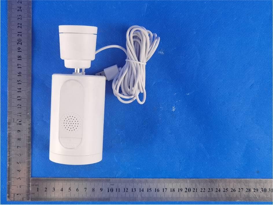
Click to zoom
Application Details
- Equipment Class
- DTS - Digital Transmission System
- Date of Grant
- Apr 20, 2023
- Application Purpose
- Original Equipment
- Date of Application
- Apr 20, 2023
- Equipment Note
- Smart Camera
- Frequency Range
- 2412.00000000 - 2462.00000000
- Country
- China
Documents & Files
Document Text
Text extracted from the exhibit documents filed with the FCC. Open a document above to read the original.
Users Manual
Bedienungsanleitung De 1.Was gibt's Neues Chatten Sie mit uns: Die Owltron App wurde um eine 24/7 ONLINE CHAT Funktion erweitert. Wenn Sie Fragen haben, klicken Sie einfach auf die Schaltfläche "Live Chat", um uns zu erreichen. immer für Sie da. 6.Owltron Kundenbetreuung Weitere Fragen zu Installationen und Nutzung? Benötigen Sie weitere Hilfe? Folgen Sie uns auf@Owltron Garantiebedingunge (Bitte kontaktieren Sie uns, um den Garantieservice zu aktivieren) Schauen Sie sich die FAQs an und führen Sie das Video an Owltron App oder auf der offiziellen Website von Owltron. (Scannen Sie den Code auf der rechten Seite) Wir bieten einen zeitnahen Online-Kundenservice per APP/ Website um GMT+8,00:00-02:00/9:30-12:00/13:30-24:00. Owltron APP Live Chat Website: https://owltroncam.com/pages/contact Tel: US&Canada Toll Free PT +1 (866)722-6296 Mon-Sun: 11:00 AM- 6:30 PM Email: [email protected] 1. 30-tägige Rückgaberichtlinie und 12-monatige Gewährleistung. 2. Professioneller technischer Support auf Lebenszeit von Owltron. 3.Wie stellt man das ein 2 Schritt 1 Laden Sie die "Owltron "APP herunter und registrieren Sie ein Konto auf der APP per E-Mail. Schritt 2 Schalten Sie die Kamera mit und stellen Sie sicher, dass Ihr Mobiltelefon sichergestellt wird ist bereits mit WLAN verbunden (nur 2,4 GHz WLAN wird unterstützt) Schritt 3 Öffnen Sie die "Owltron" -App, klicken Sie auf "+" oder "Gerät hinzufügen" -Taste ein die Homepage (Bild 1); Klicken Sie dann bitte auf "CAM R1" (Bild 2), bitte, bitte Überprüfen Sie und bestätigen Sie den Kamera -Status und klicken Sie dann auf "Weiter" (Bild 3). 3). Auf Werkseinstellungen zurücksetzen 4). Überprüfen Sie, ob das Router -Passwort WiFi -Passwort, jedoch nicht App -Konto -Passwort 5). In der Nähe des Routers und sicherstellen, dass die Netzwer- kumgebung starke und stabile Signale hat. 6). Stellen Sie sicher, dass Ihr Gerät über ein Wi-Fi-Band von 2,4 GHz hinzugefügt wurde. (Überprüfen Sie, ob das 2,4-GHz-Band und das 5-GHz-Band das gleiche Wi-Fi-Konto teilen. Wenn ja, empfehlen wir Ihnen, zwei Konten zu konfigurieren und während der Netzwerkverbindung zum 2,4-GHz-Band zu wechseln.) A: Bitte befolgen Sie diese Schritte 1). Klicken Sie auf "....", die sich in der oberen rechten Ecke der Live -Videoschnittstelle befindet. 2). Wählen Sie die "Einstellungen" aus; 3). Klicken Sie auf die "Aufzeichnungseinstellungen"; 4). Schaltet die "lokale Aufnahme" ein F2: So erfassen Sie nach dem Einsetzen der SD -Karte A: Wenn Sie die Micro -SD -Karte in die Kamera eingefügt haben, arbeiten Sie bitte unter den folgenden Schritten: 1). Öffnen Sie die App und klicken Sie oben rechts auf das Symbol Einstellungen. 2). Klicken Sie auf Aufzeichnungseinstellung Q3: How do I have my cameras automatically record a video when motion is detected? A: Befolgen Sie die folgenden Schritte: Um Fehler zu behe- ben: 1). Bitte wechseln Sie zum SD -Modus, um zu überprüfen, ob Sie Video sehen können. 2). Bitte starten Sie den Router neu und setzen Sie die Kamera zurück und verbinden Sie sie erneut, um diese Situation zu überprüfen. Wir empfehlen Ihnen, die Kamera so nah wie möglich am Router zu platzieren. 3). Ob die Kamera angezeigt werden kann, wenn das Telefon an einen Hotspot angeschlossen ist; 4). Ob andere Mobiltelefone die Kamera normal anzeigen können; 5). Überprüfen Sie, ob die Firmware die neueste Version ist. Um dies in der App zu überprüfen, wählen Sie das Symbol "TAP -Geräte - Top -Top -Top -Top -Schaltfläche - für Geräte -Updates untersuchen. Wenn das Problem bestehen bleibt, F4: Was soll ich tun, wenn mein Gerät eingefroren ist (das Video kann nicht abrufen)? 4.Storage -Methoden 1. Wolkenspeicher 1 Sie können ein Cloud -Speicherpaket abonnieren Durch die folgenden Schritte folgt die Kamera Videos automatisch speichern. 2. MICRO SD -Kartenspeicher 5. Frequent gestellte Fragen F1: Wie beheben Sie eine Überwachungskamera? A: Das weiße Licht blinkt schnell während der Verbindungen, es kann normal angeschlossen werden. Wenn sich das Licht in einem anderen abnormalen Zustand befindet, folgen Sie bitte diesen 6 schnellen Tipps, um Ihre Fehlerbehebung bei der Fehlerbehebung Ihrer Überwachungskamera zu beheben: 1). Wenn das Licht nicht weiß blinkt, versuchen Sie es mit einem anderen Kabel und stecken Sie es, um zu überprüfen 2). Software und Firmware aktualisieren Oder Sie können eine Micro -SD -Karte einfügen und dann einschalten Die Schaltfläche "Daten" zum Speichern der Ereignisaufnahmen. 2.Was ist in der Box 1 x Kurzanleitung1 x Owltron Kamera 1 x Halterung Statusleuchte Mikrofon Objektiv Micro-SD- Kartensteckplatz Sprecher Reset-Knopf 1 x Netzteil Schritt 4 Bitte richten Sie den QR -Code auf dem Telefonbildschirm mit dem aus Kameraobjektiv zum Scannen (in einer Entfernung von 15 bis 20 cm) nach dem Hören Klicken Sie auf "Hören Sie den Piepton" (Bild 4). Schritt 5 Warten, bis die Netzwerkkonfiguration erfolgreich ist, und Dann genießen Sie Ihre Kamera (Bild 5). 3). Und dann öffnen Sie bitte die lokale Aufzeichnung und wählen Sie den Aufnahmemodus aus 4). Wählen Sie die Ereignisaufzeichnung. 1 2 3 4 5 112*160mm 3.How to Set Up Step2 Power on the camera, and make sure your mobile phone is already connected to WiFi (only 2.4Ghz WiFi is supported) Step3 Open the "Owltron" APP, click "+" or "Add Device" button on the home page (Picture 1); Then click "Cam R1" (Picture 2) , please check and confirm the camera status then click " Next" (Picture 3). 1 2 Step1 Download “Owltron”APP and register an account on APP via Email. 3 2.What’s in the Box 1 x Quick Start Guide1 x Owltron Camera 1 x Bracket Status Light Microphone Lens Micro SD Card Slot Speaker Reset Button 1 x Power Adapter 4). Check whether the router passwordwifi password but not APP account password 5). Close to the router and ensure that the network environ- ment has strong and stable signals. 6). Ensure that your device has been added over a Wi-Fi band of 2.4 GHz. (Check whether the 2.4 GHz band and 5GHz band share the same Wi-Fi ac…
Text truncated - open the document above for the full version.
Attestation Statements
- Shenzhen Anta Technology Innovation Co., Ltd. - Federal Communications Commission Authorization and Evaluation Division Equipment Authorization Branch 7435 Oakland Mills Road Columbia, MD 21046 4/18/2023 U.S. Aqent Desiqnation Shenzhen Anta Technology Innovation Co., Ltd. acknowledges their consent f o r the f o llowing contact located in the United States to act as their agent for service of process for the equipment f o r which authorization is sought ( FCC ID: 2BAMV-R1 ) : Name and company of U.S. agent: USA MEI HUA TRADING INC Physical U.S. address of agent: 5379 Pine Valley CtBoulde CO 80301 United States FRN of�.J.S. agent: 0033406166 Email address of U.S. agent: [email protected] USA MEIHUA TRADING INC acknowledges their obligation to accept service of process on behalf of Shenzhen Anta Technology Innovation Co., Ltd. Shenzhen Anta Technology Innovation Co., Ltd. accepts its obligation to maintain an agent f o r the service of process in the United States for no less than one year after either the grantee has permanently terminated all marketing and importation of the applicable equipment within the U.S., or or judicial proceeding involving the conclusion of any Commission-related equipment, whichever is later. By signing this f o rm, we confirm the above and that we are aware of the application requirements listed under§2.911 ( d )(?) . Sincerely, 产 \JJ 勹 笆/^ n ,已 (PJl l6 · ;:; - 1uJilV 1 Sit [[J])OlUrSr Signature Peter Wang PM Shenzhen Anta Technology Innovation Co., Ltd. administrative Signature Harley Quinn manager USA MEIHUA TRADING INC The information provided in this letter is based on the referenced rule parts of Title 47 of the CFR as well as KDB 986446 DOI An expiration date for this le!!er does not exist. In case the U.S. a g ent chan g es, the g rai1tee is obli g ated to notify the FCC
Cover Letter(s)
Sincerely, Name/Title: Peter Wang/Product Development Manager Company: Shenzhen Anta Technology Innovation Co., Ltd. Address: Floor 4, No. 7 Factory Building, Lijincheng Industrial Park, Yousong Community, Longhua Street, Longhua District, Shenzhen Phone: 13421823901 Fax: N/A E-Mail: [email protected]
External Photos
Page 1 of 7 IC:30231-R1 FCCID:2BAMV-R1 EUTPhoto PHOTOGRAPHSOFEUT TOPOFAllEUT TOPVIEWOFEUT Page 2 of 7 IC:30231-R1 FCCID:2BAMV-R1 BOTTOMVIEWOFEUT FRONTVIEWOFEUT Page 3 of 7 IC:30231-R1 FCCID:2BAMV-R1 BACKVIEWOFEUT Page 4 of 7 IC:30231-R1 FCCID:2BAMV-R1 LEFTVIEWOFEUT RIGHTVIEWOFEUT
ID Label/Location Info
Label&Labellocation SmartCamera ModelNo.:R1 HVIN:GV-T31-PTZ-MAIN-V1.0 FCCID:2BAMV-R1 IC:30231-R1
Internal Photos
Page 5 of 7 IC:30231-R1 FCCID:2BAMV-R1 OPENVIEWOFEUT(FIGURE1) OPENVIEWOFEUT(FIGURE2) Page 6 of 7 IC:30231-R1 FCCID:2BAMV-R1 OPENVIEWOFEUT(FIGURE3) INTERNALVIEWOFEUT(FIGURE1) WIFIAntenna Page 7 of 7 IC:30231-R1 FCCID:2BAMV-R1 INTERNALVIEWOFEUT(FIGURE2) INTERNALVIEWOFAdapter ----ENDOFREPORT----
RF Exposure Info
RFExposureevaluation FCCID:2BAMV-R1 Exposurecategory:Generalpopulation/uncontrolledenvironment EUTType:ProductionUnit DeviceType:MobileDevice 1.Reference Accordingto§1.1307(b)(1),systemsoperatingundertheprovisionsofthissectionshallbe operatedinamannerthatensuresthatthepublicisnotexposedtoradiofrequencyenergy levelinexcessoftheCommission’sguidelines. Accordingto§1.1310and§2.1091RFexposureiscalculated. KDB447498D01:MobileandPortableDevicesRFExposureProceduresandEquipment AuthorizationPolicies 2.Limit LimitsforMaximumPermissibleExposure(MPE)/ControlledExposure Frequency Range(MHz) ElectricField Strength(V/m) MagneticField Strength(A/m) PowerDensity (mW/cm²) AveragingTime (minute) LimitsforOccupational/ControlledExposure 0.3–3.0 3.0–30 30–300 300–1500 1500–100,000 614 1842/f 61.4 / / 1.63 4.89/f 0.163 / / (100)* (900/f 2 )* 1.0 f/300 5 6 6 6 6 6 LimitsforMaximumPermissibleExposure(MPE)/UncontrolledExposure Frequency Range(MHz) ElectricField Strength(V/m) MagneticField Strength(A/m) PowerDensity (mW/cm²) AveragingTime (minute) LimitsforOccupational/ControlledExposure 0.3–3.0 3.0–30 30–300 300–1500 1500–100,000 614 824/f 27.5 / / 1.63 2.19/f 0.073 / / (100)* (180/f 2 )* 0.2 f/1500 1.0 30 30 30 30 30 F=frequencyinMHz *=Plane-waveequivalentpowerdensity 3.MPECalculationMethod PredicationofMPElimitatagivendistance Equationfrompage18ofOETBulletin65,Edition97-01 S=PG/4πR² Where:S=powerdensity P=powerinputtoantenna G=powergainoftheantennainthedirectionofinterestrelativetoanisotropicradiator R=distancetothecenterofradiationoftheantenna 4.AntennaInformation EUTcanonlyuseantennascertificatedasfollowsprovidedbymanufacturer; AntennaNo. ModelNo. ofantenna: Typeofantenna: Gainoftheantenna (Max.) Frequencyrange: 2.4GWIFI/PCBantenna2.46dBifor2400-2500MHz 5.ManufacturingTolerance WIFI(Peak) Frequency (MHz) 11b 241224372462 Target(dBm)101010 Tolerance±(dB)1.01.01.0 Frequency (MHz) 11g 241224372462 Target(dBm)101010 Tolerance ± (dB) 1.01.01.0 Frequency (MHz) 11n(HT20) 241224372462 Target(dBm)888 Tolerance±(dB)1.01.01.0 Frequency (MHz) 11n(HT40) 242224372452 Target(dBm)888 Tolerance±(dB)1.01.01.0 6.StandaloneMPEResult AsdeclaredbytheApplicant,theEUTisawirelessdeviceusedinafixapplication,atleast 20cmfromanybodypartoftheuserornearbypersons;fromthemaximumEUTRFoutput power,theminimumseparationdistance,r=20cm,aswellasthegainoftheusedantennais refertosection4,theRFpowerdensitycanbeobtained. ModulationType OutputpowerAntenna Gain (dBi) Antenna Gain (linear) MPE (mW/cm 2 ) MPE Limits (mW/cm 2 ) dBmmW 2.4GWIFI12.711.0092.461.760.0451.0000 Remark: 1.Outputpower(Peak)includingturn-uptolerance; 2.MPEevaluatedistanceis20cmfromusermanualprovidebymanufacturer. 7.Conclusion ----------------THEENDOFREPORT-------------- ThemeasurementresultscomplywiththeFCCLimitper47CFR2.1091fortheuncontrolled RFExposureofmobiledevice. -
Test Report
Page 1 of 42 ReportNo.:AIT23031502CW1 DongguanYaxu(AiT)TechnologyLimited No.22,Jinqianling3rdStreet,Jitigang, Huangjiang,Dongguan,Guangdong,China. TESTREPORT ClientInformation: Applicant: ShenzhenAntaTechnologyInnovationCo.,Ltd. Applicantadd.: Floor4,No.7FactoryBuilding,LijinchengIndustrialPark,Yousong Community,LonghuaStreet,LonghuaDistrict,Shenzhen Manufacturer: ShenzhenAntaTechnologyInnovationCo.,Ltd. Manufactureradd.: Floor4,No.7FactoryBuilding,LijinchengIndustrialPark,Yousong Community,LonghuaStreet,LonghuaDistrict,Shenzhen ProductInformation: ProductName: SmartCamera ModelNo.: R1 BrandName: Owltron FCCID: 2BAMV-R1 Applicablestandards: FCCPart15.247 PreparedBy: DongguanYaxu(AiT)TechnologyLimited No.22,Jinqianling3rdStreet,Jitigang,Huangjiang,Dongguan, Guangdong,China Tel.:+86-769-82020499Fax.:+86-769-82020495 DateofReceipt:2023.03.15DateofTest:2023.03.16~2023.03.20 DateofIssue:2023.03.20TestResult:Pass ThisdevicedescribedabovehasbeentestedbyDongguanYaxu(AiT)TechnologyLimitedandthe testresultsshowthattheequipmentundertest(EUT)isincompliancewiththeFCC/ISED requirements.Anditisapplicableonlytothetestedsampleidentifiedinthereport. Note:Thisreportshallnotbereproducedexceptinfull,withoutthewrittenapprovalof DongguanYaxu(AiT)TechnologyLimited,thisdocumentmaybealteredorrevisedby DongguanYaxu(AiT)TechnologyLimited,personalonly,andshallbenotedintherevisionof thedocument.Thistestreportmustnotbeusedbytheclienttoclaimproductendorsement. Reviewedby:Approvedby: SimbaHuangSeal.chen Page 2 of 42 ReportNo.:AIT23031502CW1 DongguanYaxu(AiT)TechnologyLimited No.22,Jinqianling3rdStreet,Jitigang, Huangjiang,Dongguan,Guangdong,China. 1Contents Page COVERPAGE 1CONTENTS...........................................................................................................................................................................2 2TESTSUMMARY.................................................................................................................................................................5 2.1STATEMENTOFTHEMEASUREMENTUNCERTAINTY.................................................................5 2.2MEASUREMENTUNCERTAINTY.......................................................................................................5 3TESTFACILITY....................................................................................................................................................................6 3.1Deviationfromstandard.......................................................................................................................6 3.2Abnormalitiesfromstandardconditions...............................................................................................6 3.3TestLocation.........................................................................................................................................6 4GENERALINFORMATION................................................................................................................................................7 4.1TESTFREQUENCIES.........................................................................................................................8 4.2EUTPERIPHERALLIST......................................................................................................................8 4.3TESTPERIPHERALLIST....................................................................................................................8 4.4TESTMETHODOLOGY.......................................................................................................................9 4.5DESCRIPTIONOFTESTMODES....................................................................................................10 5EQUIPMENTUSEDDURINGTEST...............................................................................................................................11 6TESTRESULTSANDMEASUREMENTDATA..........................................................................................................12 6.1Antennarequirement..........................................................................................................................12 6.1.1Standardrequirement:.............................................................................................................12 6.1.2EUTAntenna:...........................................................................................................................12 6.2ONTIMEANDDUTYCYCLE............................................................................................................13 6.2.1Standardrequirement:.............................................................................................................13 6.2.2MeasuringInstrumentsandSetting:........................................................................................13 6.2.3TestProcedures.......................................................................................................................13 6.2.4TestSetupLayout....................................................................................................................13 6.2.5EUTOperationduringTest......................................................................................................13 6.2.6Testresult.................................................................................................................................13 6.3MAXIMUMCONDUCTEDOUTPUTPEAKPOWERMEASUREMENT..........................................14 6.3.1Standardrequirement:.............................................................................................................14 6.3.2MeasuringInstruments:...........................................................................................................14 6.3.3TestProcedures:......................................................................................................................14 6.3.4TestSetupLayout.............................................................................…
Text truncated - open the document above for the full version.
Test Report
深圳市英佳创电子科技有限公司 Shenzhen Yingjiachuang Electronic Technology Co. LTD 产品天线调测报告 Product antenna commissioning report company address:Building C, Guangming Valley, Ma Tian Office, Guangming District, Data:2023.03.16 Fiction:Gao Jia Ye C h e c k: Fang Wenfeng approve: Shoreham Hotel Shenzhen T E L:0755-27810060 URL:http://www.szsyjc.com :0755-27810057 :FAX [email protected] Email 一、project overview Customer name project name 103 Antenna implementation mode 3 T5P 2.4 工作频段(MHz PCB ) G2400-2500 MHz catalog 4.Antenna profile 5.S11 STATIONARY WAVE PATTERN 6.S11 STATIONARY WAVE PATTERN 7. XZ&YZ 2D 8. XY 2D 9. Gain : Antenna profile S11 test data S11测试数据 1.802.002.202.402.602.803.003.20 Freq [GHz] 0.00 12.50 25.00 37.50 V S W R t ( 1 _ T 1 ) HFSSDesign1 XY Plot 1 m1 m2 m3 Curve Info VSWRt(1_T1) Setup1 : Sweep NameXY m12.40001.2955 m22.45001.1139 m32.50001.3192 XZ&YZ 2D图 -3.40 -1.80 -0.20 1.40 90 60 30 0 -30 -60 -90 -120 -150 -180 150 120 HFSSDesign1 E Curve Info dB(GainTotal) Setup1 : LastAdaptive Freq='2.45GHz' Phi='0deg' dB(GainTotal) Setup1 : LastAdaptive Freq='2.45GHz' Phi='90deg' XY 2D图 -9.20 -6.40 -3.60 -0.80 90 60 30 0 -30 -60 -90 -120 -150 -180 150 120 HFSSDesign1 H Curve Info dB(GainTotal) Setup1 : LastAdaptive Freq='2.45GHz' Theta='90deg' Gain 天线对应坐标图 Through simulation calculation, it is concluded that: The maximum gain of the antenna in the 2.45Ghz band is 2.46dBi.
Test Report
DongguanYaxu(AiT)TechnologyLimited ReportNo.: AIT23031502CW1 Page1 of 63 AppendixC RF Test Data for 2.4GWIFI(ConductedMeasurement) ProductName:SmartCamera TradeMark:Owltron Test Model:R1 EnvironmentalConditions Temperature: 24.6 C RelativeHumidity:52.4 % ATM Pressure:10 0.0 kPa Test Engineer:SimbaHuang Supervisedby:Seal Chen DongguanYaxu(AiT)TechnologyLimited ReportNo.: AIT23031502CW1 Page2 of 63 Contents Page COVERPAGE 1 Duty Cycle ...............................................................................................................................................................................................3 1.1 Test Result.....................................................................................................................................................................................3 1.2 Test Graphs...................................................................................................................................................................................4 2 MaximumConductedOutputPower......................................................................................................................................................10 2.1 Test Result...................................................................................................................................................................................10 3 -6dB Bandwidth.....................................................................................................................................................................................11 3.1 Test Result...................................................................................................................................................................................11 3.2 Test Graphs.................................................................................................................................................................................12 4 OccupiedChannelBandwidth...............................................................................................................................................................18 4.1 Test Result...................................................................................................................................................................................18 4.2 Test Graphs.................................................................................................................................................................................19 5 MaximumPowerSpectralDensityLevel ...............................................................................................................................................25 5.1 Test Result...................................................................................................................................................................................25 5.2 Test Graphs.................................................................................................................................................................................26 6 Band Edge .............................................................................................................................................................................................32 6.1 Test Result...................................................................................................................................................................................32 6.2 Test Graphs.................................................................................................................................................................................33 7 ConductedRF SpuriousEmission.........................................................................................................................................................41 7.1 Test Result...................................................................................................................................................................................41 7.2 Test Graphs.................................................................................................................................................................................42 8 RestrictBand .........................................................................................................................................................................................54 8.1 Test Result...................................................................................................................................................................................54 8.2 Test Graphs.................................................................................................................................................................................56 DongguanYaxu(AiT)TechnologyLimited ReportNo.: AIT23031502CW1 Page3 of 63 1 Duty Cycle 1.1 Test Result ModeFrequency(MHz)AntennaDuty Cycle(%)1/T (kHz) b2412Ant198.020.12 b2437Ant197.770.12 b2462Ant198.010.12 g2412Ant188.80.72 g2437Ant188.680.72 g2462Ant189.170.72 n202412Ant187.510.85 n202437Ant187.30.85 n202462Ant187.260.85 n402422Ant176.921.69 n402437Ant177.051.72 n402452Ant176.281.72 DongguanYaxu(AiT)TechnologyLimited ReportNo.: AIT23031502CW1 Page4 of 63 1.2 Test Graphs Test Graphs b 24 12 MHz Ant1 b 2437MHzAnt1 DongguanYaxu(AiT)TechnologyLimited ReportNo.: AIT23031502CW1 Page5 of 63 Test Graphs b 24 62 MHz Ant1 g 24 12 MHz Ant1 DongguanYaxu(AiT)TechnologyLimited ReportNo.: AIT23031502CW1 Page6 of 63 Test Graphs g 2437MHzAnt1 g 24 62 MHz Ant1 DongguanYaxu(AiT)TechnologyLimited ReportNo.: AIT23031502CW1 Page7 of 63 Test Graphs n20 24 12 MHz Ant1 n20 2437MHzAnt1 DongguanYaxu(AiT)TechnologyLimited ReportNo.: AIT23031502CW1 Page8 of 63 Test Graphs n20 24 62 MHz Ant1 n40 24 22 MHz Ant1 DongguanYaxu(AiT)TechnologyLimited ReportNo.: AIT23031502CW1 Page9 of 63 Test Graph…
Text truncated - open the document above for the full version.
Test Setup Photos
IC:30231-R1 FCCID:2BAMV-R1 TestSetup RadiatedEmission IC:30231-R1 FCCID:2BAMV-R1 ConductedEmission(ACMains)
Contact Information
Applicant
Peter Wang(PM)
Test Firm
Dongguan Yaxu (AiT) Technology LimitedCoin Tang
[email protected]+86 0769-82020499-21
Technical Specifications
| # | Rule Parts | Frequency Range | Power Output |
|---|---|---|---|
| 1 | 15C | 2.41 GHz - 2.46 GHz | 10.20 mW |