2BAQV-ZQM1001TInternet of Things Communication module
Zhongqing Yunzhi Technology (Zhejiang) Co., LTD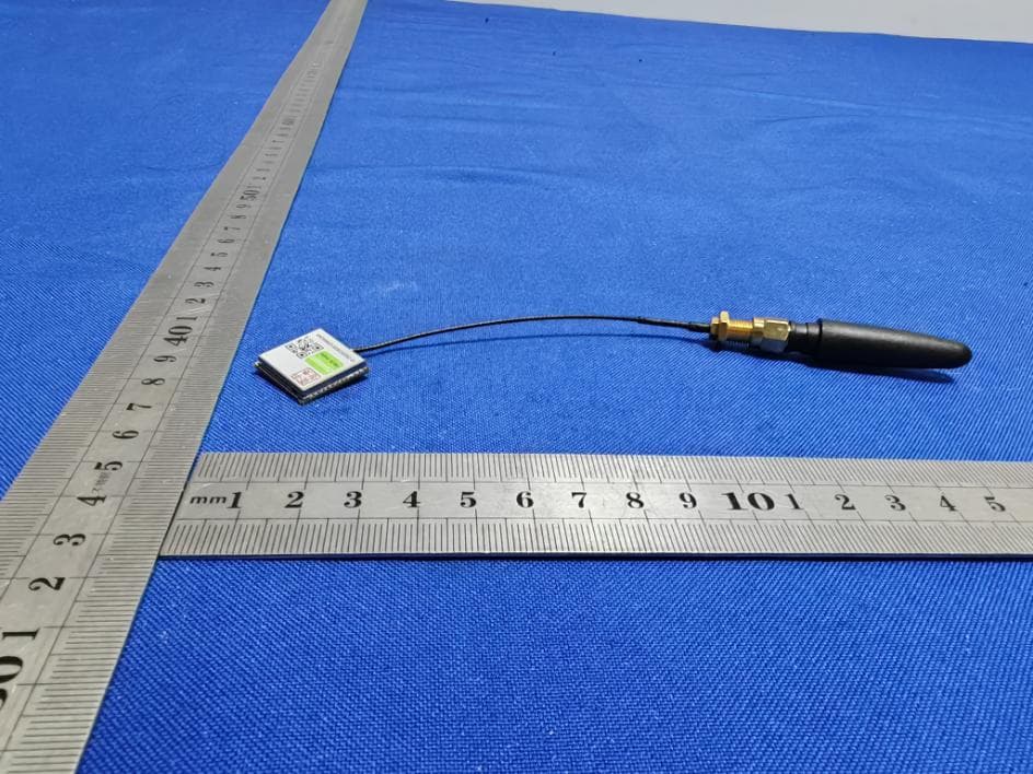
Click to zoom
Application Details
- Equipment Class
- DSC - Part 15 Security/Remote Control Transmitter
- Date of Grant
- Apr 21, 2023
- Application Purpose
- Original Equipment
- Date of Application
- Apr 21, 2023
- Equipment Note
- Internet of Things Communication module
- Frequency Range
- 433.85000000 - 433.85000000
- Country
- China
Documents & Files
Document Text
Text extracted from the exhibit documents filed with the FCC. Open a document above to read the original.
Users Manual
(1)FCC ZQM1001T Statement ZQM1001T is a 32-bit RISC-V based SoC that supports the long-range, low-power, high-capacity WIoTa wireless communication protocol and is specifically optimized for IoT applications, featuring 512KB built-in flash memory, 240KB SRAM, and a wealth of peripherals. WIoTa is a wireless communication protocol that can be flexibly configured according to different needs of the Internet of Things. It has ultra-low sensitivity of -145dbm, bandwidth of 200-400 KHz, high-order modulation of up to 3 bps/Hz, supports synchronous, asynchronous and mesh networking modes. Features RISC-V 32bit CPU core, with a floating point arithmetic unit (FPU) -160MHz maximum operating rate (except FPU and communication DSP) -Single-cycle multiplication, hardware integer division support -Support RISC-V IMFC instruction set, as well as special integer extension instructions -FPU/DSP@96Mhz -4x DMA Storage -512KB embedded NOR flash memory with unified data code storage -240 KB SRAM Low power mode -Various low power modes per embedded RTC and PMU control -Main components are independently clocked -Peripheral clock gating -RTC runs separately in low power mode RF transceiver based on WIoTa protocol -Operating frequency 433.85MHz --145 dbm sensitivity -GMSK - 8PSK modulation Clock -Built-in DCXO oscillator, need external crystal -Built-in 32KHz RC oscillator, and built-in 32KHz crystal oscillator (external crystal required) -Built-in PLL doubles the DCXO clock frequency, and the CPU supports DCXO/PLL clock switching Common peripherals -The 2x 16650, UART compatible -2x 32-bit timing counter -1x SPI Master, up to 4 peripheral chip selection signals -1x CAN bus -4x PWM module, independent output -Up to 18 GPIOs with reusable functionality -1x I 2 C interface -Three-channel 12bit ADC -10bit DAC and auxiliary DAC Encryption/decryption -PUF Chip fingerprint -AES/SM1/SM2/SM7 encryption engine SPI SLAVE burning and debugging interface - Burning IO can be reused - Four hardware breakpoints are supported Power/chip management - Built-in DCDC converter - Built-in core LDO, IO LDO - On-chip temperature detection and off-chip temperature detection FCC WARNING FCC Caution: Any changes or modifications not expressly approved by the party responsible for compliance could void the user's authority to operate this equipment. This device complies with Part 15 of the FCC Rules. Operation is subject to the following two conditions: (1) This device may not cause harmful interference, and (2) this device must accept any interference received, including interference that may cause undesired operation. This device and its antenna(s) must not be co-located or operating in conjunction with any other antenna or transmitter. 15.105 Information to the user. (b) For a Class B digital device or peripheral, the instructions furnished the user shall include the following or similar statement, placed in a prominent location in the text of the manual: Note: This equipment has been tested and found to comply with the limits for a Class B digital device, pursuant to part 15 of the FCC Rules. These limits are designed to provide reasonable protection against harmful interference in a residential installation. This equipment generates, uses and can radiate radio frequency energy and, if not installed and used in accordance with the instructions, may cause harmful interference to radio communications. However, there is no guarantee that interference will not occur in a particular installation. If this equipment does cause harmful interference to radio or television reception, which can be determined by turning the equipment off and on, the user is encouraged to try to correct the interference by one or more of the following measures: —Reorient or relocate the receiving antenna. —Increase the separation between the equipment and receiver. —Connect the equipment into an outlet on a circuit different from that to which the receiver is connected. —Consult the dealer or an experienced radio/TV technician for help. This equipment complies with FCC radiation exposure limits set forth for an uncon-trolled environment. Radiation Exposure Statement: This equipment complies with FCC radiation exposure limits set forth for an uncontrolled environment. This transmitter must not be co-located or operating in conjunction with any other antenna or transmitter. The availability of some specific channels and/or operational frequency bands are country dependent and are firmware programmed at the factory to match the intended destination. The firmware setting is not accessible by the end user. The final end product mus t be labelled in a visible area with the following: “ Contains Transmitter Module “2BAQV-ZQM1001T” Requirement per KDB996369 D03 2.2 List of applicable FCC rules List the FCC rules that are applicable to the modular transmitter. These are the rules that specifically establish the bands of operation, the power, spurious emissions, and operating fundamental frequencies. DO NOT list compliance to unintentional-radiator rules (Part 15 Subpart B) since that is not a condition of a module grant that is extended to a host manufacturer. See also Section 2.10 below concerning the need to notify host manufacturers that further testing is required.3 Explanation: This module meets the requirements of FCC part 1 5C (15.231).it Specifically identified AC Power Line Conducted Emission, Radiated Spurious emissions, Dwell Time, Occupied Bandwidth, Antenna Requirement. 2.3 Summarize the specific operational use conditions Describe use conditions that are applicable to the modular transmitter, including for example any limits on antennas, etc. For example, if point-to- point antennas are used that require reduction in power or compensation for cable loss, then this information must be in the instructions. If the use condition limitations extend to professional users, then instructions must state that this information also extends to the host manuf…
Text truncated - open the document above for the full version.
Cover Letter(s)
< Zhongqing Yunzhi Technology (Zhejiang) Co., LTD > Eurofins Electrical and Electronic Testing NA, Inc. 914 West Patapsco Avenue Baltimore, MD 21230 Company name: Zhongqing Yunzhi Technology (Zhejiang) Co., LTD FCC ID: 2BAQV-ZQM1001T Gentlemen, In accordance with 47CFR 15.212 Modular Transmitters and KDB 996369 D01 ‘Module Certification Guide v02’. FCC ID: 2BAQV-ZQM1001T has been examined against the following requirements. Items to be covered by Single modular transmitters. Requirement per 15.212 and KDB 996369 D01 ‘Modular Certification Guide v02 Explanation from Grantee (do not write yes/no, but explain why product complies/how it is achieved) 1. The radio elements must have the radio frequency circuitry shielded. Physical components and tuning capacitor(s) may be located external to the shield, but must be on the module assembly The modular have the radio frequency circuitry shielded 2. The module must have buffered modulation/data inputs to ensure that the device will comply with Part 15 requirements with any type of input signal All modulation and data inputs are buffered by circuitry on the transmitter chip ZQC1001,, as is shown in the schematic. 3. The module must contain power supply regulation on the module Power supply regulation is provided by circuitry on the transmitter chip ZQC1001, as is shown in the schematic. 4. The module must contain a permanently attached antenna, or contain a unique antenna connector, and be marketed and operated only with specific antenna(s), per Sections 15.203, 15.204(b), 15.204(c), 15.212(a), 2.929(b) EUT module contain with with the unique antenna connector . Please reference the exhibition Test Report. 5. The module must demonstrate compliance in a stand- alone configuration Please reference exhibition Test Configuration Photo for the stand-alone test configuration. 6. The module must be labelled with its permanently affixed FCC ID label, or use an electronic display (See KDB Publication 784748 about labelling requirements) The instruction on the labelling rule of the end product has been stated in the Users manual of this module. Please also see the exhibition Label Sample. 7. The module must comply with all specific rules applicable to the transmitter including all the conditions provided in the integration instructions by the grantee The required FCC rule has been fulfilled and all the instructions for maintaining compliance has been clearly stated in the Users Manual. 8. The module must comply with RF exposure requirements Please refer exhibition RF Exposure for the compliance of MPE RF exposure rule. Name: Tian Haiting Title: CEO Signature of applicant Date: 2023.04.03
Cover Letter(s)
Zhongqing Yunzhi Technology (Zhejiang) Co., LTD (2023.04.03) Eurofins Electrical and Electronic Testing NA, Inc. 914 West Patapsco Avenue Baltimore, MD 21230 RE: CONFIDENTIALITY REQUEST FOR (Internet of Things Communication module / ZQM1001T / FCC ID: 2BAQV-ZQM1001T) To Whom It May Concern: This letter serves as an official request for confidentiality under sections 0.457 and 0.459 of CFR 47. We have requested that the Exhibits Long-Term Confidentiality Short-Term Confidentiality NOTE 2 ID Label/Location No No Attestation Statement No No External Photos No ☒ Block Diagram ☒ ☐ Schematics ☒ ☐ Test Report No No Test Setup Photos No ☒ User’s Manual ☐ NOTE 1 ☒ Internal Photos ☐ NOTE 1 ☒ Parts List / Tune Up ☐ ☐ RF Exposure Info No No Operational Description ☒ ☐ Cover Letter(s) No No SDR Software / Security Info ☐ No required to be submitted with this application be permanently withheld from public review. Above mentioned document contains detailed system and equipment description are considered as proprietary information in operation of the equipment. The public disclosure of above documents might be harmful to our company and would give competitor an unfair advantage in the market. Please contact me if there is any information you may need. Sincerely, Signature: Name: Tian Haiting Title: CEO
Cover Letter(s)
Zhongqing Yunzhi Technology (Zhejiang) Co., LTD (2023.04.03) Eurofins Electrical and Electronic Testing NA, Inc. 914 West Patapsco Avenue Baltimore, MD 21230 RE: LETTER OF AGENT AUTHORIZATION To Whom It May Concern: We, the undersigned, hereby authorize (Shenzhen CTB Testing Technology Co., Ltd.) to act on our behalf in all matters relating to application for equipment authorization, including the signing of all documents relating to these matters. We also hereby certify that no party to the application authorized hereunder is subject to the denial of benefits, including FCC benefits, pursuant to Section 5301 of the Anti-Drug Abuse Act of 1988, 21 U.S.C.853(a). This agreement expires one year from the current date. Sincerely, Signature: Name: Tian Haiting Title: CEO
External Photos
External Photos ANT
ID Label/Location Info
FCC ID LABEL: Label Location: FCC ID: 2BAQV-ZQM1001T Model No.: ZQM1001T
Internal Photos
Internal Photos
RF Exposure Info
Shenzhen CTB Testing Co., Ltd. FCC ID: 2BAQV-ZQM1001T Portable device According to §15.247(e)(i) and §1.1307(b)(1), systems operating under the provisions of this section shall be operated in a manner that ensures that the public is not exposed to radio frequency energy level in excess of the Commission’s guidelines. According to KDB447498 D01 General RF Exposure Guidance V06 The 1-g SAR and 10-g SAR test exclusion thresholds for 100 MHz to 6 GHz at test separation distances ≤ 50 mm are determined by: [(max. power of channel, including tune-up tolerance, mW)/(min. test separation distance, mm)]·[√f(GHZ)] ≤ 3.0 for 1-g SAR and ≤ 7.5 for 10-g extremity SAR, where: • f(GHZ) is the RF channel transmit frequency in GHz • Power and distance are rounded to the nearest mW and mm before calculation • The result is rounded to one decimal place for comparison When the minimum test separation distance is < 5 mm, a distance of 5 mm is applied to determine SAR test exclusion. 433.85: Modulation Channel Freq. (GHz) Conduct ed power (dBm) Conducte d power (mW) Tune-up power (dBm) Max tune-up power (dBm) Max tune-up power (mW) Distance (mm) Result calculatio n SAR Exclusion threshold SAR test exclusion ASK 0.43385 -23.41 0.00 -23±1 -22.00 0.01 <5 0.00083 3.00 YES Note:dbm=dbuv/m-95.2=72.79-95.2=-22.41dBm(ERP), so the conduct peak power=-22.41-1=-23.41dBm Conclusion: For the max result : 0.00083≤ FCC Limit 3.0 for 1g SAR.
Test Report
ANT PHTOT All measurements were performed radiated and therefore additional antenna gain documentation is not required.
Test Report
Shenzhen CTB Testing Technology Co., Ltd. Report No.: CTB230328008RFX Report Tel: 4008-707-283 Web: http://www.ctb-lab.netPage 1 of 29 TEST REPORT Compiled by: Reviewed by: Approved by: Chen Zheng Arron Liu Bin Mei / Director Note: If there is any objection to the inspection results in this report, please submit a written report to the company within 15 days from the date of receiving the report. The test report is effective only with both signature and specialized stamp. This result(s) shown in this report refer only to the sample(s) tested. Without written approval of Shenzhen CTB Testing Technology Co., Ltd. this report can’t be reproduced except in full. The tested sample(s) and the sample information are provided by the client. “*” indicates the testing items were fulfilled by subcontracted lab. “#” indicates the items are not in CNAS accreditation scope. Product Name: Internet of Things Communication module FCC ID: 2BAQV-ZQM1001T Trademark: N/A Model Number: ZQM1001T Prepared For: Zhongqing Yunzhi Technology (Zhejiang) Co., LTD Address: Room 102, 6th Floor, 389 Jiangbin Road, Youzhu Street, Qingtian County, Lishui City, Zhejiang Province Manufacturer: Zhongqing Yunzhi Technology (Zhejiang) Co., LTD Address: Room 102, 6th Floor, 389 Jiangbin Road, Youzhu Street, Qingtian County, Lishui City, Zhejiang Province Prepared By: Shenzhen CTB Testing Technology Co., Ltd. Address: 1&2/F., Building A, No.26, Xinhe Road, Xinqiao, Xinqiao Street, Bao'an District, Shenzhen, Guangdong, China Sample Received Date: Mar. 13, 2023 Sample tested Date: Mar. 13, 2023 to Mar. 28, 2023 Issue Date: Mar. 28, 2023 Report No.: CTB230328008RFX Test Standards FCC Part15.231(e) ANSI C63.10:2013 Test Results PASS Remark: This is 433MHz radio test report. Shenzhen CTB Testing Technology Co., Ltd. Report No.: CTB230328008RFX Report Tel: 4008-707-283 Web: http://www.ctb-lab.net Page 2 of 29 TABLE OF CONTENT Test Report Declaration Page 1. VERSION .......................................................................... 3 2. TEST SUMMARY ................................................................... 4 3. MEASUREMENT UNCERTAINTY ..................................................... 5 4. PRODUCT INFORMATION AND TEST SETUP .......................................... 6 4.1 Product Information .................................................................... 6 4.2 Test Setup Configuration ............................................................... 6 4.3 Support Equipment .................................................................... 6 4.4 Test Mode ............................................................................ 7 4.5 Test Environment ...................................................................... 7 5. TEST FACILITY AND TEST INSTRUMENT USED ....................................... 8 5.1 Test Facility ........................................................................... 8 5.2 Test Instrument Used .................................................................. 8 6. AC POWER LINE CONDUCTED EMISSION ............................................. 11 6.1 Block Diagram Of Test Setup .......................................................... 11 6.2 Limit ................................................................................ 11 6.3 Test procedure ....................................................................... 11 6.4 Test Result .......................................................................... 12 7. RADIATED EMISSION .............................................................. 14 7.1 Block Diagram Of Test Setup .......................................................... 14 7.2 Limit ................................................................................ 14 7.3 Test procedure ....................................................................... 16 7.4 Test Result .......................................................................... 17 8. DWELL TIME ...................................................................... 22 8.1 Block Diagram Of Test Setup .......................................................... 22 8.2 Limit ................................................................................ 22 8.3 Test procedure ....................................................................... 22 8.4 Test Result .......................................................................... 23 9. OCCUPIED BANDWIDTH ........................................................... 24 9.1 Block Diagram Of Test Setup .......................................................... 24 9.2 Limit ................................................................................ 24 9.3 Test procedure ....................................................................... 24 9.4 Test Result .......................................................................... 25 10. ANTENNA REQUIREMENT ......................................................... 26 11. EUT PHOTOGRAPHS .............................................................. 27 12. EUT TEST SETUP PHOTOGRAPHS .................................................. 28 (Note: N/A means not applicable) Shenzhen CTB Testing Technology Co., Ltd. Report No.: CTB230328008RFX Report Tel: 4008-707-283 Web: http://www.ctb-lab.net Page 3 of 29 1. VERSION Report No. Issue Date Description Approved CTB230328008RFX Mar. 28, 2023 Original Valid Shenzhen CTB Testing Technology Co., Ltd. Report No.: CTB230328008RFX Report Tel: 4008-707-283 Web: http://www.ctb-lab.net Page 4 of 29 2. TEST SUMMARY The Product has been tested according to the following specifications: Test Item Test Requirement Test method Result AC Power Line Conducted Emission 47 CFR Part 15 Subpart C Section 15.207 ANSI C63.10-2013 PASS Radiated Emission 47 CFR Part 15 Subpart C Section 15.209; 15.231(e) ANSI C63.10-2013 PASS Dwell Time 47 CFR Part 15 Subpart C Section 15.231 (e) ANSI C63.10-2013 PASS Occupied Bandwidth 47 CFR Part 15 Subpart C Section 15.231(c) ANSI C63…
Text truncated - open the document above for the full version.
Test Setup Photos
Radiated Emission Below 1G Above 1G Conducted emissions
Contact Information
Applicant
Tian Haiting
Technical Contact
Zhongqing Yunzhi Technology (Zhejiang) Co., LTDTian Haiting
[email protected]13538214502
Room 102, 6th Floor, 389 Jiangbin Road, · Lishui City, Zhejiang Province · China
Test Firm
Shenzhen CTB Testing Technology Co., Ltd.Rita Xiao
[email protected]86-13538218145
Technical Specifications
| # | Rule Parts | Frequency Range | Power Output |
|---|---|---|---|
| 1 | 15.231 | 433.85 MHz - 433.85 MHz | - |