2BAU4-B4000SSTPortable Power Station
Suzhou Yoshino Power Technology Co. Ltd.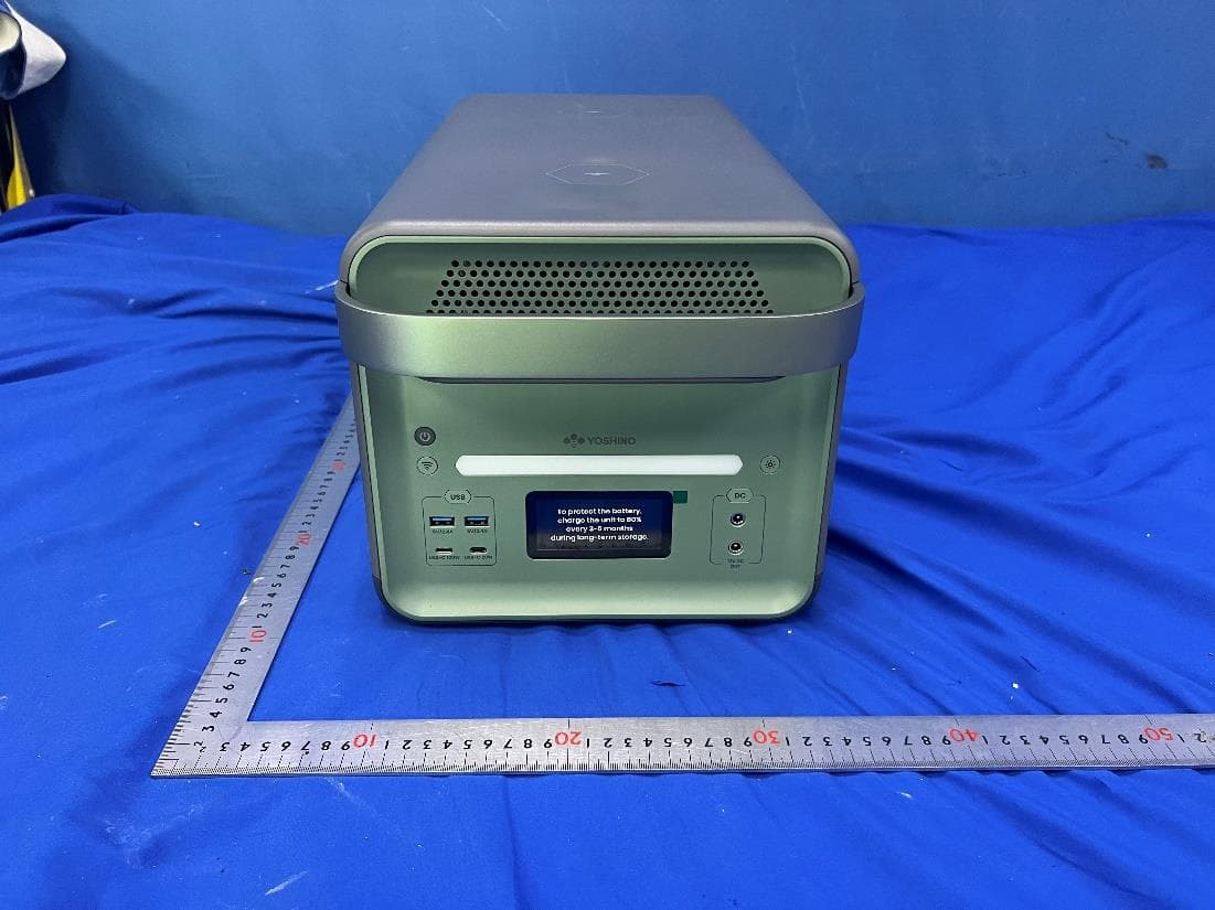
Click to zoom
Application Details
- Equipment Class
- DCD - Part 15 Low Power Transmitter Below 1705 kHz
- Date of Grant
- Sep 25, 2023
- Application Purpose
- Original Equipment
- Date of Application
- Sep 25, 2023
- Equipment Note
- Portable Power Station
- Frequency Range
- 0.11100000 - 0.20500000
- Country
- China
Documents & Files
Document Text
Text extracted from the exhibit documents filed with the FCC. Open a document above to read the original.
Users Manual
User Manual Solid-State Portable Power Station B4000 SST Tech support based in the USA! 1 (800) 513-2797 [email protected] Operating hours are 8:00 am - 4:30 pm PST (M-F). DISCLAIMER The information contained in this manual is subject to change without notice. Read all safety tips, warning messages, terms of use, and disclaimers carefully. This user manual contains instructions and notes on the operation and use of this unit. Users take full responsibility for all usage and operations. You are solely responsible for being aware of all relevant regulations and using Yoshino products in a way that is compliant. Yoshino recommends that you use genuine Yoshino accessories. Yoshino shall not be responsible for any damage or expense that might result from the use of parts other than genuine Yoshino parts. If you are not going to use the unit for an extended period of time, power off the unit and discon- nect AC adapter from the outlet. Recommended storage temperature: 32-104°F / 0-40°C, storage humidity: 90% Max. To protect the battery, charge the unit to 80% every 3-6 months during long-term storage. For your safety, please read this manual carefully before using and keep handy for future reference. YOSHINO APP Yoshino APP Google Play 1. Add device 3. Connect to the Internet Internet setup Remember password Password Loading . . . Wi-Fi name Start binding 2. Search with Bluetooth Searching for units 1 234 App Store You can use the Yoshino app to monitor, control or customize your portable power station. Download at https://yoshinopower.com 01 Tech support based in the USA! 1 (800) 513-2797 [email protected] Operating hours are 8:00 am - 4:30 pm PST (M-F). CONTENT 11 7. Smart Link Technology - Expansion Battery 10 6. UPS 13-14 9. Warranty 15 16 17 10. Troubleshooting 11. FAQ 12. FCC Warning 08 08 08 09 09 09 10 5.1 Power Button 5.2 APP Connectivity 5.3 LED Light Bar 5.4 AC Output 5.5 USB Output 5.6 DC Output 5. Operation 1. What’s in the Box02 03-04 05-06 07 07 07 08 12 2. Safety Instructions 3. Overview 4. Recharging Your Portable Power Station 4.1 AC Charging 4.2 Car Charging 4.3 Solar Charging 8. Specifications 02 Tech support based in the USA! 1 (800) 513-2797 [email protected] Operating hours are 8:00 am - 4:30 pm PST (M-F). 1. What’s in the Box B4000 SST Portable Power Station DC5521 to Cigarette Car Female Output Cable ( 1.6 ft / 0.5 m ) Cigarette Car Charging Cable ( 9.8 ft / 3 m ) Solar Charging Cable MC4 to XT60 ( 4.9 ft / 1.5 m ) User Manual, Thank You Card, Warranty Registration Card AC Recharge Cable ( 5.9 ft / 1.8 m ) 03 Tech support based in the USA! 1 (800) 513-2797 [email protected] Operating hours are 8:00 am - 4:30 pm PST (M-F). 2. Safety Instructions Important Safety Instructions WARNING – When using this product, basic precautions should always be followed, including the following: a) Read all the instructions before using the product. b) To reduce the risk of injury, close supervision is necessary when the product is used near children. c) Do not put fingers or hands into the product. d) Use of an attachment not recommended or sold by Yoshino Technology may result in a risk of fire, electric shock, or injury to persons. e) To reduce risk of damage to the electric plug and cord, pull the plug rather than the cord when disconnecting the portable power station. f) Do not use a portable power station or appliance that is damaged or modified. A damaged or modified portable power station may exhibit unpredictable behavior resulting in fire, explosion or risk of injury. g) Do not operate the portable power station with a damaged cord or plug, or a damaged output cable. h) Do not disassemble the portable power station, contact Yoshino customer service when service is required. Incorrect disassembly or reassembly may result in a risk of fire or electric shock i) To reduce the risk of electric shock, unplug the power pack from the outlet before attempting any instructed servicing. j) When charging the internal battery, work in a well ventilated area and do not restrict ventilation in any way. k) Do not expose a portable power station to fire or excessive temperature. Exposure to fire or temperature above 130°C (265°F) may cause explosion. l) Have servicing performed by a qualified repair person using only identical replacement parts. This will ensure that the safety of the product is maintained. m) Do not get the product wet or immerse it in water. If water is found inside the the product, it must not be turned on or used again. Take all precautions against shock before touching the product. Move the product to a safe open area. Once the product is safley moved, contact Yoshino customer service immediately. n) Do not use the product in an environment with strong static electricity/magnetic fields. o) Do not drop or allow the product to fall. If the product has any kind of severe external impact, turn the power off immediately and stop using the product. Dispose of the product properly. p) Do not put heavy objects on top of the product. q) Do not block the fan during use. r) This product is not recommended for powering medical emergency equipment such as medical grade ventilators and artificial lungs. Please consult with your doctor and the manufacturer for instructions on the safe use of portable power station with medical equipment. s) Please keep a safe distance between medical implants and this product while the product is in use. This portable power station will generate electromagnetic fields which can affect the normal operation of pacemakers, hearing aids, cochlear implants and other medical equipment. Please contact the manufacturer for information on the safe use of this product around these devices. 04 Tech support based in the USA! 1 (800) 513-2797 [email protected] Operating hours are 8:00 am - 4:30 pm PST (M-F). Grounding Instructions This product must be grounded. If it should malfunction o…
Text truncated - open the document above for the full version.
Attestation Statements
Suzhou Yoshino Power Technology Co. Ltd.
Attestation Statements
Suzhou Yoshino Power Technology Co. Ltd.
Cover Letter(s)
2024 -8-28
Cover Letter(s)
Suzhou Yoshino Power Technology Co. Ltd. Attention: Certification reviewer RE: Request for Confidentiality FCC ID: 2BAU4- To Whom It May Concern: Permanent Confidentiality [Complete this section if permanent confidentiality is requested] Request to withhold permanently from public review certain portions of the application for equipment certification for the referenced FCC identifiers. This request for confidentiality is made pursuant to 47 CFR 0.457(d) and 0.459 of the FCC Rules. In particular, the following sections of the application are to be kept permanently confidential: [Select one or more of items below, as appropriate] Schematics Block Diagrams Operational Description Parts List Internal Photos (see note) Users Manual (see note) Note 1: Internal Photos may be held confidential 1) if the circuit board or internal components are not accessible to users. For example, it is acceptable if the circuit board is enclosed in epoxy. 2) Also, it is acceptable if the device is not accessible to the public, for example, a device mounted on the top of a large tower (or in a fenced enclosure) such that it is only serviceable by professional designated technicians under a Non-Disclosure Agreement (NDA). All sales for these devices must be under a NDA restricting the disclosure of the propriety information, including internal photos. Users Manual may be held confidential only when the manual contains proprietary technical information intended for professional technicians obligated under a NDA. All sales and distribution of the user’s manual must be under a NDA that restricts the disclosure of the information. In the application cover letter requesting permanent confidentiality the following additional description and the NDA exhibit is required: 1. Describe in detail how internal photos and/or users manual information are controlled to prevent them from becoming public or disclosed to unauthorized persons. 2. Describe how public access is restricted for products serviceable by professional designated technicians. 3. A statement that all sales of the non-consumer device will be under a NDA to include third party sales and that the final user of the device is subject to the NDA. 4. Provide an example of the NDA between the grantee and a purchaser. The request for confidentiality must Note 2: For scanning receiver, the schematics, block diagrams, operational description, tune-up procedure, parts list and internal photos are always held permanently confidential. Short-term Confidentiality [Complete this section if short-term confidentiality is requested] Request to withhold from public review for a period of days from the date of the Grant of Equipment Authorization and prior to marketing, certain portions of the application for equipment certification for the referenced FCC identifiers. This request for confidentiality is made pursuant to 47 CFR 0.457(d) and 0.459 of the FCC Rules. In particular, the following sections of the application are to be kept short-term confidential for a period above from the date of the grant [Select one or more of items below that are not selected in the list above, as appropriate] Schematics Block diagrams Operational Description Tune-up Procedure [ 180] BOM B4000SST Parts List Test Setup Photos External Photos Internal Photos Users Manual Rationale for request for confidentiality: We have invested considerable time and materials in research and development to produce the referenced product. Permanent confidentiality: Disclosure of the permanently confidential portions of this application to competitors would not only give them significant competitive advantages in developing similar products, but would also disclose successful implementation of unpublished, leading edge technology developed by us. Short-term confidentiality: Disclosure of the short-term confidential portions of this application during the period of importation and/or distribution would reveal key aspects of proprietary technology to competitors and diminish the value of our investment in research and development. If you have questions or need further information, please contact the undersigned. Sincerely, 2023-08-28
ID Label/Location Info
Model: B4000 SST Battery Capacity: 2562Wh, 47.45V, 54Ah Input Ports: AC Input: 100-120VAC, 50/60Hz Charging Mode : 1800W Max Bypass Mode: 12A Max Car Input: 12VDC/10A, 120W Max Solar Input: 12-60VDC/10A Max, 600W Max Output Ports: AC Output: 2 AC Outlets, 50/60Hz TT-30R Outlet, 50/60Hz Inverter Mode: AC Outlets, 120VAC/20A Max Each Port TT-30R Outlet, 120VAC/30A Max, 4000W Total Bypass Mode: 100-120VAC, 12A Max, 1454VA/1440W Max 12V DC Output: 2 Ports, 12.6VDC/10A, 126W Total USB-A Output: 2 Ports, 5VDC/2.4A, 12W Each Port USB-C PD Output: 5-15VDC/3A, 20VDC/5A, 100W Max USB-C Output: 5VDC/3A, 9VDC/2.22A, 12VDC/1.66A, 20W Max Wireless Charging: 2 Ports, 5VDC/1A, 9VDC/1.1A, 12VDC/1.25A, 15W Max Each Port www.yoshinopower.com Discharging Temperature: 14 to 104°F / -10 to 40°C Charging Temperature: 32 to 104°F / 0 to 40°C Working Humidity: Maximum 90% S/N: Made in China YXB40002305A00001 DANGER: CAUTION: WARNING: Read instruction manual before using. Do not use in damp or wet conditions. Do not use this product if any cables and cords are damaged. Connect only to properly grounded outlets. Risk of injury to persons. This device is not intended for use in a commercial repair facility. Use in a well ventilated area. Do not overcharge the internal battery. Keep unit away from sparks and flames. Risk of electric shock and risk of fire. This device is not to be stored in a vehicle. This unit is not waterproof. Do not use in wet or damp conditions. Always store indoors. Avoid direct sunlight! 5025868 CONFORMS TO UL STD. 2743 Keep Dry UN38.3FCC ID: 2BAU4-B4000SST Contains FCC ID: 2AC7Z-ESPC3MINI1 B4000SST Model: B4000 SST Battery Capacity: 2611Wh, 48.36V, 54Ah Input Ports: AC Input: 100-120VAC, 50/60Hz Charging Mode : 1800W Max Bypass Mode: 12A Max Car Input: 12VDC/10A, 120W Max Solar Input: 12-60VDC/10A Max, 600W Max Output Ports: AC Output: 2 AC Outlets, 50/60Hz TT-30R Outlet, 50/60Hz Inverter Mode: AC Outlets, 120VAC/20A Max Each Port TT-30R Outlet, 120VAC/30A Max, 4000W Total Bypass Mode: 100-120VAC, 12A Max, 1454VA/1440W Max 12V DC Output: 2 Ports, 12.6VDC/10A, 126W Total USB-A Output: 2 Ports, 5VDC/2.4A, 12W Each Port USB-C PD Output: 5-15VDC/3A, 20VDC/5A, 100W Max USB-C Output: 5VDC/3A, 9VDC/2.22A, 12VDC/1.66A, 20W Max Wireless Charging: 2 Ports, 5VDC/1A, 9VDC/1.1A, 12VDC/1.25A, 15W Max Each Port www.YoshinoPower.com Discharging Temperature: 14 to 104°F / -10 to 40°C Charging Temperature: 32 to 104°F / 0 to 40°C Working Humidity: Maximum 90% S/N: Made in China YXB40002305A00001 DANGER: CAUTION: WARNING: Read instruction manual before using. Do not use in damp or wet conditions. Do not use this product if any cables and cords are damaged. Connect only to properly grounded outlets. Risk of injury to persons. This device is not intended for use in a commercial repair facility. Use in a well ventilated area. Do not overcharge the internal battery. Keep unit away from sparks and flames. Risk of electric shock and risk of fire. This device is not to be stored in a vehicle. This unit is not waterproof. Do not use in wet or damp conditions. Always store indoors. Avoid direct sunlight! 5025868 CONFORMS TO UL STD. 2743 Keep Dry UN38.3FCC ID: 2BAU4-B4000SST Contains FCC ID: 2AC7Z-ESPC3MINI1 B4000 SST 160mmX50mm
RF Exposure Info
INTERTEK TESTING SERVICES FCC ID: 2BAU4-B4000SST 1 RF Exposure The equipment under test (EUT) is Portable Power Station with Wireless Charging function operating 111KHz-205KHz, 2.4G WIFI function operating in 2412-2462MHz and BT(BLE) function operating in 2402MHz~2480MHz. The EUT is powered by AC Input: 100-120VAC, 50/60Hz or Car Input: 12VDC/10A, 120W Max; or Solar Input: 12-60VDC/10A, Max, 600W Max . For more detail information pls. refer to the user manual. Wireless Charging: Antenna type: Integral Antenna(embedded coil antenna) The maximum H-Field Strength of the EUT is: 0.0947A/m. 2.4GHz WiFi: Antenna Type: Integral Antenna. Antenna1 Gain: 3.96dBi. Modulation Type: BPSK, QPSK, 16QAM, 64QAM, CCK, DQPSK, DBPSK and DSSS. According to FCC Part 2.1091, this unlicensed transmitting devices is categorically excluded from routine environmental evaluation for RF exposure prior to equipment authorization or use, According to the KDB 447498 and OET 65, the simple calculation as below: The source-based time averaged maximum radiated power = 20dBm +3.96dBi = 23.96dBm = 248.886mW From above data, the exposed power density at a distance (R) of 20cm from the center of radiation of the antenna for 2.4GHz band can be calculated according to OET 65 as follow: = 248.886mW/ 4πR^2 = 0.0495 mW/cm^2 <1mW/cm^2 INTERTEK TESTING SERVICES FCC ID: 2BAU4-B4000SST 2 The MPE limit is 1.0 mW/cm^2 for general population and uncontrolled exposure in the WIFI frequency range according to FCC Part 1.1310. As the measured power density at 20cm from the transmitter is lower than the MPE limit, the compliance to the MPE limit can be ensured by indicating the minimum 20cm separation between the transmitter's radiating structure and body of the user or nearby persons. BT(BLE): Antenna Type: Integral Antenna. Antenna1 Gain: 3.96dBi. Modulation Type: GFSK. According to FCC Part 2.1091, this unlicensed transmitting devices is categorically excluded from routine environmental evaluation for RF exposure prior to equipment authorization or use, According to the KDB 447498 and OET 65, the simple calculation as below: The source-based time averaged maximum radiated power = 6.0dBm +3.96dBi = 9.96dBm =9.9083mW From above data, the exposed power density at a distance (R) of 20cm from the center of radiation of the antenna for 2.4GHz band can be calculated according to OET 65 as follow: = 9.9083mW/ 4πR^2 = 0.00197 mW/cm^2 <1mW/cm^2 The MPE limit is 1.0 mW/cm^2 for general population and uncontrolled exposure in the WIFI frequency range according to FCC Part 1.1310. As the measured power density at 20cm from the transmitter is lower than the MPE limit, the compliance to the MPE limit can be ensured by indicating the minimum 20cm separation between the transmitter's radiating structure and body of the user or nearby persons. Simultaneous: BT antenna and 2.4G WiFi antenna can not transmit Simultaneous; For Simultaneous transmitting of 2.4GHz WiFi +Wireless Charging and BT+Wireless Charging, According to 865664D02 2.2 d) 1): 2.4GHz WiFi +Wireless Charging: The sum of the ratios of the spatially averaged results to the applicable frequency dependent MPE limits = 0.0495/1 + 0.0947/1.63 = 0.1076 < 1 BT+Wireless Charging: The sum of the ratios of the spatially averaged results to the applicable frequency dependent MPE limits = 0.00197/1 + 0.0947/1.63 = 0.0601 < 1 INTERTEK TESTING SERVICES FCC ID: 2BAU4-B4000SST 3 Since the sum of the MPE ratios for all simultaneously transmitting antennas incorporated in the device is ≤ 1.0, the EUT is considered to satisfy MPE compliance for simultaneous transmission operations. The following RF exposure statement or similar sentence is proposed to be included in the user manual: “FCC RF Radiation Exposure Statement Caution: This Transmitter must be installed to provide a separation distance of at least 20 cm from all persons.” -End-
Test Report
Suzhou Yoshino Power Technology Co. Ltd. TEST REPORT SCOPE OF WORK FCC TESTING–B4000 SST REPORT NUMBER 230804015SZN-001 ISSUE DATE [REVISED DATE] 06 SEPTEMBER 2023 [---------------------] PAGES 23 DOCUMENT CONTROL NUMBER FCC ID 209_b © 2017 INTERTEK Intertek Report No.: 230804015SZN-001 This report is for the exclusive use of Intertek's Client and is provided pursuant to the agreement between Intertek and its Client. Intertek's responsibility and liability are limited to the terms and conditions of the agreement. Intertek assumes no liability to any party, other than to the Client in accordance with the agreement, for any loss, expense or damage occasioned by the use of this report. Only the Client is authorized to permit copying or distribution of this report and then only in its entirety. Any use of the Intertek name or one of its marks for the sale or advertisement of the tested material, product or service must first be approved in writing by Intertek. The observations and test results in this report are relevant only to the sample tested. This report by itself does not imply that the material, product, or service is or has ever been under an Intertek certification program. Intertek Testing Services Shenzhen Ltd. Longhua Branch 101, 201, Building B, No. 308 Wuhe Avenue, Zhangkengjing Community, GuanHu Subdistrict, LongHua District, ShenZhen. Tel: (86 755) 8601 6288 Fax: (86 755) 8601 6751 Version: 01-November-2017 Page: 1 of 23 FCC ID 209_b TEST REPORT 101, 201, Building B, No. 308 Wuhe Avenue, Zhangkengjing Community, GuanHu Subdistrict, LongHua District, ShenZhen. Tel: (86 755) 8601 6288 Fax: (86 755) 8601 6751 www.intertek.com Suzhou Yoshino Power Technology Co. Ltd. Application For Certification FCC ID: 2BAU4-B4000SST Portable Power Station Model: B4000 SST Transmitter Report No.: 230804015SZN-001 We hereby certify that the sample of the above item is considered to comply with the requirements of FCC Part 15, Subpart C for Intentional Radiator, mention 47 CFR [10-1-21] Prepared and Checked by: Approved by: Rode Liu Ryan RQ Chen Project Engineer Project Engineer Date: 06 September 2023 Intertek Report No.: 230804015SZN-001 Version: 01-November-2017 Page: 2 of 23 FCC ID 209_b TEST REPORT MEASUREMENT/TECHNICAL REPORT This report concerns (check one) Original Grant X Class II Change Equipment Type: DCD - Part 15 Low Power Transmitter Below 1705 kHz Deferred grant requested per 47 CFR 0.457(d)(1)(ii)? Yes No X If yes, defer until : date Company Name agrees to notify the Commission by: date of the intended date of announcement of the product so that the grant can be issued on that date. Transition Rules Request per 15.37? Yes No X If no, assumed Part 15, Subpart C for intentional radiator - the new 47 CFR [10-01-21] Edition] provision. Report prepared by: Rode Liu Intertek Testing Services Shenzhen Ltd. Longhua Branch 101, 201, Building B, No. 308 Wuhe Avenue, Zhangkengjing Community, GuanHu Subdistrict, LongHua District, ShenZhen. Tel: (86 755) 8614 0743 Fax: (86 755) 8601 6751 Intertek Report No.: 230804015SZN-001 Version: 01-November-2017 Page: 3 of 23 FCC ID 209_b TEST REPORT Table of Contents 1.0 Summary of Test Results .................................................................................... 4 2.0 General Description ............................................................................................. 5 2.1 Product Description ............................................................................................. 5 2.2 Related Submittal(s) Grants ................................................................................ 5 2.3 Test Methodology ............................................................................................... 6 2.4 Test Facility......................................................................................................... 6 3.0 System Test Configuration .................................................................................. 7 3.1 Justification ......................................................................................................... 7 3.2 EUT Exercising Software .................................................................................... 7 3.3 Special Accessories ............................................................................................ 7 3.4 Equipment Modification ....................................................................................... 8 3.5 Measurement Uncertainty ................................................................................... 9 3.6 Support Equipment List and Description ............................................................ 9 4.0 Measurement Results ........................................................................................ 11 4.1 Field Strength Calculation ................................................................................. 11 4.2 Radiated Emission Configuration Photograph ................................................... 12 4.3 Radiated Spurious Emission ............................................................................. 12 4.4 Conducted Emission Configuration Photograph ................................................ 16 4.5 Conducted Emission ......................................................................................... 16 5.0 Equipment Photographs .................................................................................... 19 6.0 Product Labelling ............................................................................................... 19 7.0 Technical Specifications .................................................................................... 19 8.0 Instruction Manual ............................................................................................. 19 9.0 Miscellaneous Information ................................................................................ 20 9.1 20dB Bandwidth ..................................................…
Text truncated - open the document above for the full version.
Test Report
Suzhou Yoshino Power Technology Co. Ltd. TEST REPORT SCOPE OF WORK SAR Assessment– B4000 SST REPORT NUMBER 230804015SZN-002 ISSUE DATE [REVISED DATE] 06 September 2023 [--------------------] PAGES 8 DOCUMENT CONTROL NUMBER RF Exposure © 2017 INTERTEK TEST REPORT Intertek No.: 230804015SZN-002 This report is for the exclusive use of Intertek's Client and is provided pursuant to the agreement between Intertek and its Client. Intertek's responsibility and liability are limited to the terms and conditions of the agreement. Intertek assumes no liability to any party, other than to the Client in accordance with the agreement, for any loss, expense or damage occasioned by the use of this report. Only the Client is authorized to permit copying or distribution of this report and then only in its entirety. Any use of the Intertek name or one of its marks for the sale or advertisement of the tested material, product or service must first be approved in writing by Intertek. The observations and test results in this report are relevant only to the sample tested. This report by itself does not imply that the material, product, or service is or has ever been under an Intertek certification program. Intertek Testing Services Shenzhen Ltd. Longhua Branch 101, 201, Building B, No. 308 Wuhe Avenue, Zhangkengjing Community, GuanHu Subdistrict, LongHua District, ShenZhen. Tel: (86 755) 8601 6288 Fax: (86 755) 8601 6751 Version: 01-November-2017 Page 1 of 8 RF Exposure 101, 201, Building B, No. 308 Wuhe Avenue, Zhangkengjing Community, GuanHu Subdistrict, LongHua District, ShenZhen. Tel: (86 755) 8601 6288 Fax: (86 755) 8601 6751 www.intertek.com Test Report Applicant : Suzhou Yoshino Power Technology Co. Ltd. No.3 Shengxi Road, Kunshan Development Zone, Kunshan City, Jiangsu 215335, P.R.China Sample Description : Portable Power Station Product Model No. : B4000 SST Brand Name Electrical Rating : Input: AC Input: 100-120VAC, 50/60Hz Charging Mode: 1800W Max Bypass Mode:12A Max Car Input: 12VDC/10A, 120W Max Solar Input: 12-60VDC/10A, Max, 600W Max Wireless Charging: 2Ports, 5VDC/1A, 9VDC/1.1A, 12VDC/1.25A Date Received : 04 August 2023 Date Test Conducted : 04 August 2023 to 05 September 2023 Test Requested : Test for compliance with CFR 47 part 1 Test Method : Environmental evaluation and exposure limit according to FCC CFR 47 part 1, 1.1307(c) and (d), 1.1310 KDB 680106 D01 RF Exposure Wireless Charging App v03r01 Test Result : Pass Conclusion : When determining of test conclusion, measurement uncertainty of tests have been considered. ******************************** End of Page ******************************* Prepared and Checked By: Approved By: Rode Liu Ryan RQ Chen Project Engineer Project Engineer Date: 06 September 2023 TEST REPORT Intertek No.: 230804015SZN-002 Version: 01-November-2017 Page 2 of 8 RF Exposure Test Report Test Setup Configuration Note - The RF exposure test is performed in the shield room. - The test distance is between the edge of the charger and the geometric centre of probe. Test Equipment List Equipment No. Equipment Manufacturer Model No. Serial No. Cal. Date Due Date SZ186-04 Electric and Magnetic Field Analyzer Narda EHP-50F 510WY90119 2023-07-10 2024-07-10 TEST REPORT Intertek No.: 230804015SZN-002 Version: 01-November-2017 Page 3 of 8 RF Exposure This product was tested in the following configuration: Description Manufacturer Detail Wireless charging load (Provided by Intertek) / / Laptop (Provided by Intertek) Lenovo T420 Laptop (Provided by Intertek) DELL P137G Cement Resistance (Provided by Intertek) / 2ohm*2, 1.67ohm, 4ohm, 7.2ohm, 1.26ohm*2, 2.52ohm DC5521 to DC5521 Cable (Provided by Intertek) / 0.8meter, unshielded USB-C to C Cable (Provided by Intertek) / 1.0meter, unshielded USB-C Cable (Provided by Intertek) / 0.6meter, unshielded USB-A Cable (Provided by Intertek) / 0.7meter, unshielded USB-A Cable (Provided by Intertek) / 0.7meter, unshielded AC Cable (Provided by Applicant) / 1.8meter, unshielded Cigarette Car Charging Cable (Provided by Applicant) / 3.0meter, unshielded Solar Charging Cable (Provided by Applicant) / 1.5meter, unshielded DC5521 to Cigarette Car Female Output Cable / 0.5meter, unshielded Justification Pertest mode Description Mode 1 Standby mode Mode 2 Bypass + Wireless charging load is charging at 1% battery power + USB Output + DC Output Mode 3 Inverter + Wireless charging load is charging at 1% battery power + USB Output + DC Output Mode 4 Bypass + Wireless charging load is charging at 50% battery power + USB Output + DC Output The EUT was powered by AC Input: 100-120VAC, 50/60Hz or Car Input: 12VDC/10A, 120W Max; or Solar Input: 12-60VDC/10A, Max, 600W Max input during the test. The test system was pre-scanning tested based on the consideration of above EUT operation mode. and only the worst-case data was shown in this report. TEST REPORT Intertek No.: 230804015SZN-002 Version: 01-November-2017 Page 4 of 8 RF Exposure Reference Limit: Environmental evaluation and exposure limit according to FCC CFR 47 part 1, 1.1307(c) and (d), 1.1310 According to FCC 1.1310: The criteria listed in the following table shall be used to evaluate the environment impact of human exposure to radio frequency (RF) radiation. LIMITS FOR MAXIMUM PERMISSIBLE EXPOSURE (MPE) Frequency Range ( MHz ) Electric Field strength (V/m) Magnetic Field Strength (A/m) Power Density (mW/cm 2 ) Average Time (minutes) (A) Limits for Occupational/Controlled Exposure 0.3 – 3.0 614 1.63 (100) * 6 (B) Limits for General Population/Uncontrolled Exposure 0.3 – 1.34 614 1.63 (100) * 30 Note: * = Plane wave equivalent power density Test Result: During test, the mobile handset is being charged. Worst Case Operating Mode: Mode 2 Test Result for wireless power transmit part: H-Field Strength at 15 cm surrounding the EUT and 20cm above the top surface of the EUT Frequency Range (MHz) EUT Operation mode Probe Position Front (A/m) Probe Position Rear (A/m) Probe Position Left (A/m) Probe Position …
Text truncated - open the document above for the full version.
Test Setup Photos
The EUT is placed at the center of turntable
Contact Information
Applicant
xi zhou
Technical Contact
Intertek Testing Services Shenzhen Ltd. Longhua BrWilliam Chen
[email protected]+8675586140627
101, 201, Building B, No. 308 Wuhe Avenue, Zhangke · Shenzhen · China
Non-Technical Contact
Intertek Testing Services Shenzhen Ltd. Longhua BrWilliam Chen
[email protected]+8675586140627
Test Firm
Intertek Testing Services Shenzhen Ltd. Longhua BrHolly Ou
[email protected]+86 755 86140691
Technical Specifications
| # | Rule Parts | Frequency Range | Power Output |
|---|---|---|---|
| 1 | 15C | 0.111 MHz - 0.205 MHz | - |
Other Applications from Suzhou Yoshino Power Technology Co. Ltd.
2BAU4-B2000SST
Aug 06, 2023Portable Power Station
Equipment Class
DCD - Part 15 Low Power Transmitter Below 1705 kHz