FCCID.CO- FCC ID Database
HomeCompaniesEquipment ClassesSearch

© 2026 FCC ID Database. All rights reserved.

AboutContactData sourced from FCC public records
  1. Home/
  2. TriTerra Technology Limited/
  3. 2BB2G-KAIHON1000

2BB2G-KAIHON1000Kaihon 1000

TriTerra Technology Limited
Kaihon 1000 - FCC ID 2BB2G-KAIHON1000 - TriTerra Technology Limited
Click to zoom

Application Details

Equipment Class
DTS - Digital Transmission System
Date of Grant
Nov 28, 2023
Application Purpose
Original Equipment
Date of Application
Nov 27, 2023
Equipment Note
Kaihon 1000
Frequency Range
2412.00000000 - 2462.00000000
Company
TriTerra Technology Limited
Country
China

Documents & Files

Select a file to view

Users Manual

↗

Attestation Statements

↗
↗

Cover Letter(s)

↗
↗
↗

External Photos

↗

ID Label/Location Info

↗

Internal Photos

↗

RF Exposure Info

↗

Test Report

↗
↗
↗
↗

Test Setup Photos

↗

Document Text

Text extracted from the exhibit documents filed with the FCC. Open a document above to read the original.

Users Manual

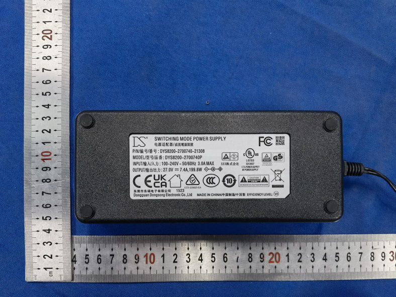
Kaihon1000 USER MANUAL PORTABLE POWER STATION CHARGE ME NOW IMPORTANT SAFETY INSTRUCTIONS Before using or storing, plug your TriTerra Kaihon into the wall un�l it is fully charged. Keep your TriTerra Kaihon plugged in when not in use. For more �ps and tricks on keeping your ba�ery healthy, learn more from the educa�on sec�on. Read all the instruc�ons and cau�ons carefully before use to avoid personal injury or damage to the unit and any connected products. Observe all Input/Output connectors ra�ngs: To avoid fire or electrical shock hazard, observe all ra�ngs on unit, and products you intend to use; check manuals for more informa�on. Use in ven�lated area: Ensure proper ven�la�on while in use and do not obstruct fan openings on unit. Inadequate ven�la�on may cause damage to the unit. Do not stack anything on top of the unit in storage or in use. LOCK THE TOP COVER in wet condi�ons: In order to avoid short circuits or electric shock, make sure the top cover of unit is always closed and locked and do not allow the opera�on panel of the unit to get wet. Let the opera�on panel of unit dry completely before using. Shock or Fire Hazard: TriTerra generates the same poten�ally lethal AC power as a normal household wall outlet. Please use it carefully just like normal AC outlet on the wall. DO NOT insert foreign objects into outputs or ven�la�on holes. DO NOT a�empt to replace the internal ba�ery with anything other than the authorised replacement ba�ery available from TriTerra. Any manipula�on to the unit or its components will void all warran�es. Table of Contents Ge�ng Started i. Get to Know Your Gear ii. How it Works ii. Charging from the Wall Charging Your TriTerra Kaihon i. Charging from Solar Using Your TriTerra Kaihon 2 3 i. How to use ii. Best-Use Strategy 6 iv. Touch Screen iii. Cold Weather Usage 7 7 7 - 10 10 v. Top Cover10 vi. Touch Screen Wake-Up Bu�on Detachable Torch 11- 12 Detachable Trolley (op�onal Purchase)13 Storage and Down�me Maintenance 18 Technical Specifica�ons 14- 15 Frequently Asked Ques�ons 16- 18 Mobile Applica�on 19- 20 1 Warranty and Contact 21- 23 Troubleshoo�ng20 4 - 5 5 - 6 Get to Know Your Gear AC Plug to the wall for power charging AC Adaptor DC7909 Connector to DC INPUT C8 Connector to AC INPUT 9:30am INPUT WA TT S WA TT S ----- 100% OUTPUT ----- Detachable Torch DC INPUT for DC7909 Connector AC INPUT for C8 Connector AC Outputs Touch Screen Touch Screen Wake-Up Bu�on 12V Output, up to 10A USB-C PD 5/9/12/15/20V, up to 5A (100W) USB-C 5V, 3A (15W) USB Ouputs 5V, up to 1.5A (7.5W) 2 For safety, please always connects the C8 Connector to the AC INPUT jack of Kaihon when charging. How it Works Power Charging It Empowers AC Plug (with AC/DC Transformer) 6.5 hours Solar (Sold separately) 6.5 hours (depends on climate) Fridge 15+ hours 800W AC 1+ hours 12V LED 300+ hours 600W Boiler 10+ �mes 3 Charge Your TriTerra Kaihon CHARGE ME NOW: Before using or storing, plug your TriTerra Kaihon into the wall un�l it is fully charged. Keep your TriTerra Kaihon plugged in when not in use. For more �ps and tricks on keeping your ba�ery healthy, see the educa�on sec�on. When charging your TriTerra Kaihon you will no�ce a ba�ery segment blinking in the display. This indicates the current charge status. Once your TriTerra Kaihon is fully charged, all ba�ery segments will be lit and remain solid. As long as there is more power going into the TriTerra Kaihon than is being pulled from the output ports, the display will also indicate an es�mated �me un�l fully charged. This is an es�mated �me based on the power input and output numbers at that �me; it will gradually adjust to a shorter or longer �me as the average charge or discharge rates fluctuate. Charging from Solar IMPORTANT NOTE: Do not exceed 35.2V input into the DC Input port; doing so will cause damage to the unit and poten�al bodily injury. For ques�ons about solar recharging and proper way to set up your solar panels, email our solar experts at [email protected]. TriTerra Solar Panel is recommended to use with Kaihon by simply connec�ng its DC7909 plug to the DC INPUT jack of Kaihon. The maximum input power is 200W. 1. Place your solar panel where it will get as much direct sunlight as possible. 2. Plug the DC7909 plug to the DC INPUT jack of Kaihon according to the figure on P.5. You will know the Kaihon is charging when the ba�ery segments on the touch screen are blinking. 3. You can also connect the Kaihon to other brands of solar panels via the DC INPUT jack. (Cau�on: NO Excess 35.2V Input) 4 TriTerra Kaihon Solar Charging: Connec�on Configura�on Maximum Power Point Tracker TriTerra Kaihon features maximum power point tracker internally. It ac�vately monitors the energy source you’re using to charge the TriTerra Kaihon and op�mizes the source to maxmize power, resul�ng in up to 40% faster charge �mes. Charging from the wall Using the included AC Adaptor, plug your TriTerra Kaihon into any wall outlet. You will know the Kaihon is charging when the ba�ery segments on the touch screen are blinking. The Kaihon is fully charged when all the ba�ery segments stop blinking and remain solid. The Kaihon should recharge from the wall in about 5.5 hours. TriTerra Solar DC7909 Connector to DC INPUT 1. The AC Cable comes with two connectors besides the AC wall plug, one connects to the AC Adaptor and the another one which is C8 Connector which connects to the AC INPUT of Kaihon. 5 Using your TriTerra Kaihon How to use your TriTerra Kaihon: IMPORTANT NOTE: The TriTerra Kaihon is not compa�ble recharging from a 12V source, it can result in damage to the unit, cable, as well as your vehicle. 2. DC7909 Connector from the AC Adaptor connects to the DC INPUT of Kaihon. 1. Press the Touch Screen Wake-Up Bu�on to switch on the touch screen for manipula�on. 2. Scroll the touch screen to the page showing the par�cular power output ports. (see illustra�on below) 3. Click the icon of a par�cular power output port to turn it on. When not…

Text truncated - open the document above for the full version.

Attestation Statements

TriTerraTechnologyLimited U.S.AgentDesignationforServiceofProcess (ApplicantandU.S.AgentareSeparateParties) TO:FederalCommunicationsCommission 7435OaklandMillsRoad Columbia,MD21046 ATTENTION:FCCCertification–Section2.911(d)(7)Information DesignatedU.S.Agent CompanyName:BaihetianInnovativeSolutions FRN:0033401605 ContactName:KennethYoung StreetAddress:6837ChaseRd City/Province/Zip:Dearborn,MI48126 TelephoneNo:313-395-3113 Email:[email protected] Thisletteristoconfirmthatwe(“theDesignatedU.S.Agent)haveacceptedtheresponsibilitytoactasthe DesignatedU.S.AgentforServiceofProcessasrequiredbysection47CFR2.911(d)(7)onbehalfofthe Applicantnotedbelow. U.S.AgentSignature: Date: Signedby(PrintedName/Title): TheApplicantacknowledgesthattheymustmaintainanagentfornolessthanoneyearafterterminatingall marketingandimportationORtheconclusionofanyCommission-relatedproceedinginvolvingthe equipment.TheapplicantfurtheracknowledgestheirresponsibilitytoinformtheFCCwheneverthe DesignatedU.S.Agentinformationabovechanges. Applicant Companyname:TriTerraTechnologyLimited GranteeCode:2BB2G FCCID:2BB2G-KAIHON1000 ContactName:LamKwunYu StreetAddress:Rm17,14/F,BlockB,Hi-TechIndustrialCentre,491-501CastlePeakRoad,TsuenWan,N.T. HongKong TelephoneNo:+85262161668 Email:[email protected] ApplicantSignature: Date:Nov.14,2023 Signedby(PrintedName/Title):LamKwunYu/AssistantTechnicalManager

Attestation Statements

TriTerraTechnologyLimited FederalCommunicationsCommission AuthorizationandEvaluationDivision 7435OaklandMillsRoad Columbia,MD21046 USA Date:November14,2023 FCCID:2BB2G-KAIHON1000 Ref.#1:AttestationStatementsPart2.911(d)(5)(i)Filing TriTerraTechnologyLimitedcertifiesthattheequipmentforwhichauthorizationissoughtis not“covered”equipmentprohibitedfromreceivinganequipmentauthorizationpursuantto section2.903oftheFCCrules. Ref.#2:AttestationStatementsPart2.911(d)(5)(ii)Filing TriTerraTechnologyLimited certifiesthat,asofthedateofthefilingoftheapplication, theapplicantisnotidentifiedontheCoveredListasanentityproducing“covered” equipment. Applicant:TriTerraTechnologyLimited Address:Rm17,14/F,BlockB,Hi-TechIndustrialCentre,491-501CastlePeakRoad,Tsuen Wan,N.T.HongKong ContactPerson:LamKwunYu Tel.:+85262161668 Email:[email protected] Sincerely, Signature:

Cover Letter(s)

SmallSize2.4GHzPCBAntenna-AN043 1KEYWORDS PCBantenna AverageGain2dBi ESP32 IOTapplication 2.4GHz InvertedFAntenna 2INTRODUCTION ThePCBantennadescribedinthisapplicationnoteisnowusedonESP32modulereference design.However,itcanalsobeusedinall2.4GHzdesigns,especiallysmallspaceisrequiredfor theantenna. Thisapplicationnotedescribestheantennadimensions,theRFperformanceandconsiderationsfor complyingwithregulatorylimitswhenusingthisdesign. Thesuggestedantennadesignrequiresnomorethan15.2x5.7mmofspaceandensuresaVSWR ratiooflessthan2acrossthe2.4GHzISMbandwhenconnectedtoa50ohmsource. Figure1:ESP32 3ANTENNADESIGN ThePCBantennaontheESP32ModulereferencedesignisameanderedInvertedFAntenna(IFA).The IFAwasdesignedtomatchanimpedanceof50ohmat2.45GHz.Thusnoadditionalmatching componentsarenecessary. 3.1DesignGoals Thereflectionatthefeedpointoftheantennadetermineshowmuchoftheappliedpoweris deliveredtotheantenna.Areflectionoflessthan-10dBacrossthe2.4GHzISMband,when connectedtoa50ohmsource,wasadesigngoal.Reflectionoflessthan-10dB,orVSWRlessthan2, ensuresthatmorethan90%oftheavailablepowerisdeliveredtotheantenna.Bandwidthisinthis documentdefinedasthefrequencybandwheremorethan90%oftheavailablepowerisdeliveredto theantenna.AnotherdesigngoalwastofitthesizeofthePCBantennaontheesp32Moduleandto obtaingoodperformancealsowhenitisusedinIOTapplications. 3.2Simulation IE3DfromZeland,whichisanelectromagneticsimulationtool,wasusedtodesigntheantenna.The accuracyofthesimulationiscontrolledbythemesh.Anincreaseofthemeshincreasesthesimulation time.Thus,forinitialsimulationsmesh=1shouldbeused.Whenafairlygoodresultisachieveda highermeshshouldbeusedtoobtainmoreaccurateresults.Comparisonofsimulationand measurementresultsshowsthatthemeasuredreflectionisbetweentheresultobtainedwithmesh= 5andmesh=1;seeFigure2fordetails. Figure2:ComparisonofSimulationandMeasurementsResults 3.3LayoutandImplementation Smallchangesoftheantennadimensionsmayhavelargeimpactontheperformance.Thereforeitis stronglyrecommendedtomakeanexactcopyofthereferencedesigntoachieveoptimum performance.ItisalsorecommendedtousethesamethicknessandtypeofPCBmaterialasusedin thereferencedesign.Tocompensateforathicker/thinnerPCBtheantennacouldbemadeslightly shorter/longer. Figure3:AntennaDimensions L13.94 L22.70 L35.00 L42.64 L52.00 L64.90 W10.90 W20.50 D10.50 D20.30 D30.30 D40.50 D51.40 D61.70 Table1:AntennaDimensions 4TESTRESULTS Reflection,radiationpatternandvariationofoutputpoweracrossawidefrequencybandwere measuredtoverifytheperformanceofthePCBantenna. 4.1Reflection Allthereflectionmeasurementswereperformedwithanetworkanalyzerconnectedtoasemi-rigid coaxcable,whichwassolderedtothefeedpointoftheantenna.Becauseofthesmallsizeantenna andthesmallgroundplanethiskindofmeasurementsisheavilyaffectedbythepresenceand placementofthecoaxcable.Thisinfluencecanresultinasmalluncertaintyinresonancefrequency andmeasuredreflection.Typicallydifferentplacementofthesemi-rigidcoaxcablecouldchangethe resonancefrequencywith5-10MHzandthereflectionwith3-4dB. Figure4:InfluenceofPlasticEncapsulationandTestPins ThesizeofthegroundplaneaffectstheperformanceofthePCBantenna.Solderingesp32toatest boardincreasesthesizeofthegroundplaneandthustheperformanceisaffected.However, bandwidthstillcanbeenoughtocoverthewhole2.4GHzISMband. 4.2RadiationPattern Theradiationpatternfortheantennaimplementedontheesp32referencedesignhasbeenmeasured inananechoicchamber.Figure6throughFigure11showsradiationpatternsforthreeplanes,XY,XZ andYZ,measuredwithverticalandhorizontalpolarization.Allmeasurementswereperformedwith0 dBmoutputpower.Figure5showshowthedifferentradiationpattersarerelatedtothepositioningof theantenna. Figure5:HowtoRelatetheAntennatotheRadiationPatterns Figure6:AN043XYPlane Figure7:AN043XZPlane Figure7:AN043YZPlane 4.3OutputPower Tomakearealisticbandwidthmeasurementoftheantennaasmalltestprogramwasused.Thetest programsteppedthecenterfrequencyofacarrierfrom2.3to2.8GHz.Thisbandwidthmeasurement wasalsodonetoverifytheresultfromthereflectionmeasurements,describedinsection5.1.The outputpowerwasmeasuredusingmaxholdonaspectrumanalyzer.CC2511wasprogrammedfor0 dBmoutputpowerandtheantennawashorizontallyorientedanddirectedtowardsthereceiving antenna.Thiscorrespondsto0°intheXYplaneonFigure6.Thebandwidthmeasurementswerenot performedwithacorrectionfactoronthespectrumanalyzer.Thus,theresultsinFigure15andFigure 16onlyshowtherelativechangesinoutputpowerandnottheactuallevel.Figure15showsthe bandwidthoftheantennawhenthedongleisnotconnectedtoacomputer.Theresultshowsthatthe antennahasavariationinoutputpoweroflessthan3dBacrossafrequencybandofmorethan350 MHz.Thisdemonstratesthattheantennahasabroadbandcharacteristic.Maximumoutputpoweris measuredtobeat2.54GHz.ThusifthesameantennaisimplementedonaPCBwithsimilarsizeandif theapplicationisonlyintendedforstandaloneusagetheantennacouldbemadeslightlylongerto obtainbestperformanceat2.42GHz. Figure8:OUTPUTPOWER,esp32 5.4SpuriousEmissionandHarmonics Table2showsmeasuredoutputpowerandemissionatthesecondharmonic.Abovethesecond harmonicnopeaksweredetectedwhenmeasuringTXemission.ThiscanbeseenfromFigure16. ThesemeasurementswereperformedaccordingtoFCCrequirements. Table2:MeasuredLevelofOutputPowerandHarmonics FCClimitforoutputpowerandTXspuriousemissionareshowninTable3.FCCallowsforupto20dB higheremissionifdutycyclingisused.Thus,itispossibletousetheantennadescribedinthis documentandbecompliantwithFCCregulation. FCC15.247FCC15.249 2.4–2.483GHz125dBμV/m 116dBμV/m** 94dBμV/m 2.harm54dBμV/m54dBμV/m *Dependsonthepowerclass. **Dependsonthenumberofchannelsbeingused. Table3:FCCLimits 5CONCLUSION Thisapplicationnoteshowsthatitispossibletoimplementa2.4GHzantennaonasmallareaandstill achievegoodperformance.Table4liststhemostimportantpropertiesoftheInvertedFAntenna, describedinthisdocument.Thefreelineofsight(LOS)rangewasmeasuredwith250kbpsand1% PER. GaininXYplane2.3dBi GaininXZplane2.2dBi GaininYZplane1.8dBi Gaininaverage2.0dBi LOSrange240m Antennasize15.2x5.7mm Table4:IFAProperties(Measuredonesp32ReferenceDesign) Theresultsprov…

Text truncated - open the document above for the full version.

Cover Letter(s)

TriTerraTechnologyLimited Date:Nov.14, 2023 ProductModelNumber:Kaihon1000 FCC ID:2BB2G-KAIHON1000 To whomit may concern, Re: ProductCertificationRepresentativeAuthorizationLetter We authorizeQAI LaboratoriesLtd. 3980 North FraserWay, BurnabyB.C. CanadaV5J 5K5 to act on our behalfon all mattersconcerningthe above namedequipment. This shall includethe following: Testing Approvalapplicationsand procedures We declare that ORGANIZATION. is allowed to forward all information related to the approval project to the applied certification body and to the notification entities and to discuss any issues concerning the approval application. Any and all acts carried out by ORGANIZATION. on our behalf shall have the same effect as acts of our own. By: ContactListedon FCC Wesbite Title: AssistantTechnicalManager Email:[email protected] Telephone:+85262161668 On behalfof: TriTerraTechnologyLimited

Cover Letter(s)

TriTerraTechnologyLimited OfficeofEngineeringTechnology FederalCommunicationsCommission 7435OaklandMillsRoad Columbia,MD21046 USA Date:November14,2023 Subject;RequestforConfidentiality FCCID:2BB2G-KAIHON1000 ToWhomItMayConcern, PursuanttotheprovisionsoftheCommission’srulesTitle47Sections§0.457and§0.459,we arerequestingtheCommissiontowithholdthefollowingattachment(s)asconfidential documentsfrompublicdisclosureindefinitely. Thesedocumentscontaindetailedsystemandequipmentdescriptionsandareconsideredas proprietaryinformationinoperationoftheequipment.Thepublicdisclosureofthese documentsmightbeharmfultoourcompanyandwouldgivecompetitorsanunfairadvantage inthemarket. SchematicDiagram BlockDiagram PartsList OperationalDescription Tune-upProcedure SoftwareSecurityRequirementsforUNIIdevices Inadditionaltoabovementioneddocuments,inordertocomplywiththemarketingregulations inTitle47CFR§2.803andtheimportationrulesinTitle47CFR§2.1204,whileensuringthat businesssensitiveinformationremainsconfidentialuntiltheactualmarketingofnewly authorizeddevices,werequestShortTermConfidentialityofthefollowingattachment(s); ExternalPhotos TestSetupPhotos InternalPhotos UserManual For45days,pursuanttoPublicNoticeDA04-1705. OR For180dayspursuanttoKDB726920D01. Itisourunderstandingthatallmeasurementtestreports,FCCIDlabelformatand correspondenceduringthecertificationreviewprocesscannotbegrantedasconfidential documentsandthisinformationwillbeavailableforpublicreviewoncethegrantofequipment authorizationisissued. Sincerely, Signature: Name:LamKwunYu Title:AssistantTechnicalManager

External Photos

FCCID:2BB2G-KAIHON1000Page 1 of 4 ReportNo.:CTL2305121091-WF ExternalPhotosofEUT FCCID:2BB2G-KAIHON1000Page 2 of 4 ReportNo.:CTL2305121091-WF FCCID:2BB2G-KAIHON1000Page 3 of 4 ReportNo.:CTL2305121091-WF FCCID:2BB2G-KAIHON1000Page 4 of 4 ReportNo.:CTL2305121091-WF

ID Label/Location Info

FCCID:2BB2G-KAIHON1000Page 1 of 1 ReportNo.:CTL2305121091-WF FCC-IDLabelInformation 1.Labellocation: ProductName:Kaihon1000 Model:Kaihon1000 FCCID:2BB2G-KAIHON1000 Thisdevicecomplieswithpart15oftheFCCRules. Operationissubjecttothefollowingtwoconditions: (1)Thisdevicemaynotcauseharmfulinterference, and(2)thisdevicemustacceptanyinterference received,includinginterferencethatmaycause undesiredoperation.

Internal Photos

FCCID:2BB2G-KAIHON1000Page 1 of 12 ReportNo.:CTL2305121091-WF InternalPhotosofEUT FCCID:2BB2G-KAIHON1000Page 2 of 12 ReportNo.:CTL2305121091-WF FCCID:2BB2G-KAIHON1000Page 3 of 12 ReportNo.:CTL2305121091-WF BT/WIFIAntenna FCCID:2BB2G-KAIHON1000Page 4 of 12 ReportNo.:CTL2305121091-WF FCCID:2BB2G-KAIHON1000Page 5 of 12 ReportNo.:CTL2305121091-WF FCCID:2BB2G-KAIHON1000Page 6 of 12 ReportNo.:CTL2305121091-WF FCCID:2BB2G-KAIHON1000Page 7 of 12 ReportNo.:CTL2305121091-WF FCCID:2BB2G-KAIHON1000Page 8 of 12 ReportNo.:CTL2305121091-WF FCCID:2BB2G-KAIHON1000Page 9 of 12 ReportNo.:CTL2305121091-WF FCCID:2BB2G-KAIHON1000Page 10 of 12 ReportNo.:CTL2305121091-WF FCCID:2BB2G-KAIHON1000Page 11 of 12 ReportNo.:CTL2305121091-WF FCCID:2BB2G-KAIHON1000Page 12 of 12 ReportNo.:CTL2305121091-WF

RF Exposure Info

FCCID:2BB2G-KAIHON1000Page1of4ReportNo.:CTL2305121091-WF FCCRFExposureEvaluation 1.ProductInformation FCCID2BB2G-KAIHON1000 ProductNameKaihon1000 TestModelKaihon1000 PowerSupply Input:AC100-240V~50/60Hz Output:DC5V,DC9V,DC12V,DC15V,DC20V, AC100-240V~50/60Hz ModulationType BluetoothLE:GFSK 2.4GWIFI:IEEE802.11b:DSSS IEEE802.11/g/n:OFDM AntennaType Bluetooth:PCBAntenna WIFI:PCBAntenna AntennaGain Bluetooth:2.3dBi 2.4GWIFI:2.3dBi FrequencyRange Bluetooth:2402–2480MHz 2.4GWIFI:2412MHz~2462MHz ExposureCategoryGeneralpopulation/uncontrolledenvironment EUTTypeProductionUnit DeviceTypeMobileDevice 2.EvaluationMethodandLimit SystemsoperatingundertheprovisionsofFCC47CFRsectionshallbeoperatedinamannerthat ensuresthatthepublicisnotexposedtoradiofrequencyenergylevelinexcessoftheCommission’s guidelines. Inaccordancewith47CFRFCCPart2SubpartJ,section2.1091thisdevicehasbeendefinedas mobiledevicewherebyadistanceof0.2mnormallycanbemaintainedbetweentheuserandthe device,andbelowRFPermissibleExposurelimitshallcomplywith. InaccordancewithKDB447498D01forSimultaneoustransmissionMPEtestexclusionapplieswhen thesumoftheMPEratiosforallsimultaneoustransmittingantennasincorporatedinahostdevice, basedonthecalculated/estimated,numericallymodelledormeasuredfieldstrengthsorpower density,is≤1.0.TheMPEratioofeachantennaisdeterminedattheminimumtestseparation distancerequiredbytheoperatingconfigurationsandexposureconditionsofthehostdevice, accordingtotheratiooffieldstrengthsorpowerdensitytoMPElimit,atthetestfrequency.Either themaximumpeakorspatiallyaveragedresultsfrommeasurementsornumericalsimulationsmay beusedtodeterminetheMPEratios.SpatialaveragingdoesnotapplywhenMPEisestimatedusing simplecalculationsbasedonfar-fieldplane-waveequivalentconditions.Theantennainstallation andoperatingrequirementsforthehostdevicemustmeettheminimumtestseparationdistances requiredbyallantennas,inbothstandaloneandsimultaneoustransmissionoperations,tosatisfy compliance. 3.Limit 3.1ReferEvaluationMethod ANSIC95.1–1999:IEEEStandardforSafetyLevelswithRespecttoHumanExposuretoRadioFrequency ElectromagneticFields,3kHzto300GHz. FCCKDBpublication447498D01GeneralRFExposureGuidancev06:MobileandPortableDevicesRF ExposureProceduresandEquipmentAuthorizationPolicies. FCCCFR47part11.1310:Radiofrequencyradiationexposurelimits. FCCCFR47part22.1091:Radiofrequencyradiationexposureevaluation:mobiledevices 3.2Limit LimitsforMaximumPermissibleExposure(MPE)/ControlledExposure Frequency Range(MHz) ElectricField Strength(V/m) MagneticField Strength(A/m) PowerDensity (mW/cm²) AveragingTime (minute) FCCID:2BB2G-KAIHON1000Page2of4ReportNo.:CTL2305121091-WF LimitsforOccupational/ControlledExposure 0.3–3.0 3.0–30 30–300 300–1500 1500–100,000 614 1842/f 61.4 / / 1.63 4.89/f 0.163 / / (100)* (900/f 2 )* 1.0 f/300 5 6 6 6 6 6 LimitsforMaximumPermissibleExposure(MPE)/UncontrolledExposure Frequency Range(MHz) ElectricField Strength(V/m) MagneticField Strength(A/m) PowerDensity (mW/cm²) AveragingTime (minute) LimitsforOccupational/ControlledExposure 0.3–3.0 3.0–30 30–300 300–1500 1500–100,000 614 824/f 27.5 / / 1.63 2.19/f 0.073 / / (100)* (180/f 2 )* 0.2 f/1500 1.0 30 30 30 30 30 F=frequencyinMHz *=Plane-waveequivalentpowerdensity 4.MPECalculationMethod PredicationofMPElimitatagivendistance Equationfrompage18ofOETBulletin65,Edition97-01 S=PG/4πR² Where:S=powerdensity P=powerinputtoantenna G=powergainoftheantennainthedirectionofinterestrelativetoanisotropicradiator R=distancetothecenterofradiationoftheantenna 5.AntennaInformation CPW-1canonlyuseantennascertificatedasfollowsprovidedbymanufacturer; Antennatypeand antennanumber Operatefrequencyband Maximumantenna gain Note PCBAntenna 2402MHz-2480MHz 2412MHz-2462MHz Bluetooth:2.3dBi 2.4GWIFI:2.3dBi Bluetooth&WLAN Antenna 6.ConductedPowerResults [BLE] ModeChannelFrequency(MHz)PeakConductedOutputPower(dBm) 1M 02402-1.70 192440-0.97 392480-1.95 [2.4GWIFIMaxConductedPower] ModeChannelFrequency(MHz) MaxConductedPower(dBm) IEEE802.11b 12412 7.35 62437 6.80 112462 5.97 IEEE802.11g 12412 5.20 62437 4.92 FCCID:2BB2G-KAIHON1000Page3of4ReportNo.:CTL2305121091-WF 112462 4.17 IEEE802.11n HT20SISO 12412 4.14 62437 3.77 112462 3.06 7.ManufacturingTolerance <BLE-1M> GFSK(Peak) ChannelChannel0Channel19Channel39 Target(dBm)-1-1-1 Tolerance±(dB)1.01.01.0 <2.4GWIFI> 11B(Average) ChannelChannel1Channel6Channel11 Target(dBm)776 Tolerance±(dB)1.01.01.0 11G(Average) ChannelChannel1Channel6Channel11 Target(dBm)555 Tolerance±(dB)1.01.01.0 11N20(Average) ChannelChannel1Channel6Channel11 Target(dBm)444 Tolerance±(dB)1.01.01.0 8.EvaluationResults 8.1StandaloneMPE AsdeclaredbytheApplicant,theEUTisawirelessdeviceusedinafixapplication,atleast20cm fromanybodypartoftheuserornearbypersons;fromthemaximumEUTRFoutputpower,the minimumseparationdistance,r=20cm,aswellasthegainoftheusedantennarefertoantenna information,theRFpowerdensitycanbeobtained. BLE ModulationType OutputpowerAntenna Gain (dBi) Antenna Gain (linear) Duty Cycle MPE (mW/cm 2 ) MPE Limits (mW/cm 2 ) dBmmW GFSK-10.79432.31.6982100%0.00031.0000 2.4GWIFI ModulationType OutputpowerAntenna Gain (dBi) Antenna Gain (linear) Duty Cycle MPE (mW/cm 2 ) MPE Limits (mW/cm 2 ) dBmmW 802.11b75.01192.31.6982100%0.00171.0000 802.11g53.16232.31.6982100%0.00111.0000 802.11n2042.51192.31.6982100%0.00081.0000 Emark: 1.Outputpowerincludingtune-uptolerance; 2.MPEevaluatedistanceis20cmfromusermanualprovidebymanufacturer; FCCID:2BB2G-KAIHON1000Page4of4ReportNo.:CTL2305121091-WF 8.2SimultaneousTransmissionMPE ThisproductdoesnotsupportsimultaneousTransmission. 9.Conclusion ThemeasurementresultscomplywiththeFCCLimitper47CFR2.1091fortheuncontrolledRF Exposureofmobiledevice. .......................THEENDOFREPORT.........................

Test Report

ShenzhenCTLTestingTechnologyCo.,Ltd. Tel:+86-755-89486194E-mail:[email protected] TESTREPORT FCCPART15.247 ReportReferenceNo.....................:CTL2305121091-WF02 Compiledby: (position+printedname+signature) HappyGuo (Fileadministrators) Testedby: (position+printedname+signature) WuqiangWu (TestEngineer) Approvedby: (position+printedname+signature) IvanXie (Manager) ProductName.................................: Kaihon1000 Model/Typereference....................:Kaihon1000 ListModel(s)....................................:N/A TradeMark.......................................: Kaihon FCCID ............................................... : 2BB2G-KAIHON1000 Applicant’sname...........................: TriTerraTechnologyLimited Addressofapplicant.....................: Rm17,14/F,BlockB,Hi-TechIndustrialCentre,491-501Castle PeakRoad,TsuenWan,N.T.HongKong TestFirm...........................................: ShenzhenCTLTestingTechnologyCo.,Ltd. AddressofTestFirm ..................... : ZoneA,1stFloor,Warehouse2,BaishaLogisticsCompany,No. 3011ShaheWestRoad,NanshanDistrict,Shenzhen Testspecification...........................: Standard............................................:FCCPart15.247:Operationwithinthebands902-928MHz, 2400-2483.5MHzand5725-5850MHz. TRFOriginator..................................: ShenzhenCTLTestingTechnologyCo.,Ltd. MasterTRF ....................................... :Dated2011-01 Dateofreceiptoftestitem .......... : Oct.07,2023 DateofTestDate............................: Oct.07,2023-Oct.20,2023 DateofIssue .................................... : Oct.24,2023 Result................................................: Pass ShenzhenCTLTestingTechnologyCo.,Ltd.Allrightsreserved. Thispublicationmaybereproducedinwholeorinpartfornon-commercialpurposesaslongasthe ShenzhenCTLTestingTechnologyCo.,Ltd.isacknowledgedascopyrightownerandsourceofthe material.ShenzhenCTLTestingTechnologyCo.,Ltd.takesnoresponsibilityforandwillnotassume liabilityfordamagesresultingfromthereader'sinterpretationofthereproducedmaterialduetoits placementandcontext. V1.0Page2of27ReportNo.:CTL2305121091-WF02 TESTREPORT TestReportNo.:CTL2305121091-WF02 Oct.24,2023 Dateofissue EquipmentunderTest: Kaihon1000 SampleNo:CTL2305121091 Model/Type: Kaihon1000 ListedModels : N/A Applicant: TriTerraTechnologyLimited Address : Rm17,14/F,BlockB,Hi-TechIndustrialCentre, 491-501CastlePeakRoad,TsuenWan,N.T.Hong Kong Manufacturer: ShenZhenBeitiliEnergyCo.Ltd. Address : 3rdFloor,No.11,TongfubuIndustrialZone,Dabo Community,DalangStreet,LonghuaDistrict, Shenzhen TestresultPass* *Intheconfigurationtested,theEUTcompliedwiththestandardsspecifiedpage5. Thetestresultspresentedinthisreportrelateonlytotheobjecttested. Thisreportshallnotbereproduced,exceptinfull,withoutthewrittenapprovaloftheissuingtesting laboratory. V1.0Page3of27ReportNo.:CTL2305121091-WF02 **ModifiedHistory** RevisionsDescriptionIssuedDataReportNo.Remark Version1.0InitialTestReportRelease2023-10-24CTL2305121091-WF02TracyQi V1.0Page4of27ReportNo.:CTL2305121091-WF02 TableofContentsPage 1.SUMMARY.......................................................................................................................................................................5 1.1.TESTSTANDARDS............................................................................................................................................................5 1.2.TESTDESCRIPTION...............................................................................................................................................................5 1.3.TESTFACILITY.....................................................................................................................................................................6 1.4.STATEMENTOFTHEMEASUREMENTUNCERTAINTY.....................................................................................................................6 2.GENERALINFORMATION.................................................................................................................................................8 2.1.ENVIRONMENTALCONDITIONS...............................................................................................................................................8 2.2.GENERALDESCRIPTIONOFEUT.............................................................................................................................................8 2.3.DESCRIPTIONOFTESTMODESANDTESTFREQUENCY................................................................................................................9 2.4.EQUIPMENTSUSEDDURINGTHETEST...................................................................................................................................10 2.5.RELATEDSUBMITTAL(S)/GRANT(S)....................................................................................................................................10 2.6.MODIFICATIONS................................................................................................................................................................10 3.TESTCONDITIONSANDRESULTS...................................................................................................................................11 3.1.CONDUCTEDEMISSIONSTEST..............................................................................................................................................11 3.2.RADIATEDEMISSIONSANDBANDEDGE.................................................................................................................................14 3.3.MAXIMUMCONDUCTEDOUTPUTPOWER.............................................................................................................................22 3.4.POWERSPECTRALDENSITY.................................................................................................................................................23 3.5.6DBBANDWIDTH...........................................................…

Text truncated - open the document above for the full version.

Test Report

ShenzhenCTLTestingTechnologyCo.,Ltd. Tel:+86-755-89486194E-mail:[email protected] TESTREPORT FCCPART15.247 ReportReferenceNo..................…

Text truncated - open the document above for the full version.

Contact Information

Applicant

Lam Kwun Yu(Assistant Technical Manager)
[email protected]+85262161668Fax: /

Technical Contact

TriTerra Technology Limited
[email protected]

China

Test Firm

Shenzhen CTL Testing Technology Co., Ltd.Tracy Qi
[email protected]86-755-89486194

Technical Specifications

#Rule PartsFrequency RangePower Output
215C2.41 GHz - 2.46 GHz5.40 mW
Confidentiality
Long Term
Grant Notes
Power listed is the maximum conducted output power. The antennas used with this transmitter must be installed to provide a minimum separation distance of at least 20 cm from all persons and must not be co-located or operating in conjunction with any other antenna or transmitter, except in accordance with FCC multi- transmitter product procedures. End-users must be provided with operating procedures for satisfying RF exposure compliance.