2BB44-MMDVMMMDVM Hotspot
Shenzhen HKCNMA Co., Ltd.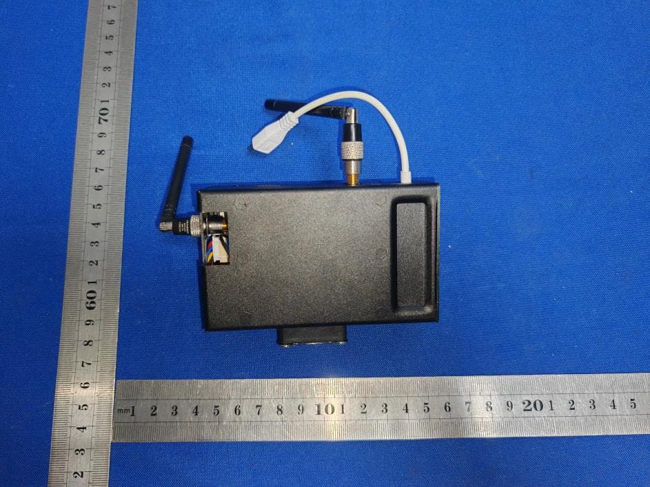
Click to zoom
Application Details
- Equipment Class
- DSC - Part 15 Security/Remote Control Transmitter
- Date of Grant
- Jul 20, 2023
- Application Purpose
- Original Equipment
- Date of Application
- Jul 20, 2023
- Equipment Note
- MMDVM Hotspot
- Frequency Range
- 433.93000000 - 433.93000000
- Company
- Shenzhen HKCNMA Co., Ltd.
- Country
- China
Documents & Files
Document Text
Text extracted from the exhibit documents filed with the FCC. Open a document above to read the original.
Users Manual
★ Fast booting ups Pi-Star for Ethernet Do the fast booting ups and skip step 1 and Jump to Step 2-e II Go to ype WiFi name, network Password , Submit, the file “wpa_supplicant.conf“is generated, Drag the file “wpa_supplicant.conf” onto the "Boot" volume of your Pi-Star TF card. And then, plug the TF card into your HOTSPOT and power up, Please wait for 2 minutes. Then we go to http://pi-star.local open the HOTSPOT settings page. www.pistar.uk/wifi_builder.phpSSID: TPSK: Type the wireless – 1 – Manual INTERNET Power Bank Ethernet Router LAN LAN LAN LAN WAN 1.Please set your RADIO RX frequency to 433.000MHz and TX ; Plug Ethernet Cable in the Hotspot’s Ethernet Cable port; Power on, Jump to Step 2-e II) to Configuration view in the manual. frequency to 433.000MHz Wait for 2 minutes. 2. 3. 4. ★ Step 1: Booting up Pi-Star for desktop computer If you need to configure a new WiFi network using Auto AP please skip step1 and go to step2, you need a wireless internet computer. ★ Step 2-a: ★ Step 2-b: For all boot-ups Power on your hotspot. Wait for Pi-Star to boot up, which normally takes two minutes or so Using Auto AP and setting up a new WiFi connection Perform this step when you start Pi-Star for the first time or when you need to connect to a new WiFi network, for example, when traveling. When Pi-Star doesn't find a known network within two minutes after boot up completes, Auto AP will automatically activate its own access point, and you'll use that to connect to Pi-Star in order to configure WiFi settings. Wait at least two more minutes for Auto AP to activate its access point. On a Windows, Mac, or Linux-based computer (not the hotspot itself) that has WiFi enabled, look in the WiFi settings to find the Pi-Star access point, and then select it to connect to it: If you're starting Pi-Star for the first time, it'll be named "pi-star" or "Pi-Star-Setup." This is what it looks like on a Mac: 1) 2) 1) 2) ★ Step 2: Booting up Pi-Star for laptop computer() and skip step 2, go to step 3, read the wireless internet computer If you use a desktop computer please do Step1Warning Connect computer Wi-Fi to “Pi-Star” or “Pi-Star-setup” AP. In computer browser, navigate to Pi-Star > Configuration > Wireless Configuration, and then add wireless network. IV Reboot Pi-Star hotspot. While rebooting, re-connect computer Wi-Fi to wireless network. V After Pi-Star hotspot reboots, it will connect to now known wireless network. In computer browser, navigate to Pi-Star. VI After boot-up, Pi-Star begins looking for known wireless networks. Power on Pi-Star hotspot to start boot up. Computer Wi-Fi is connected to wireless network Auto AP requires RPi 0W I II If no known wireless network found within 2 minutes, Pi-Star Auto AP creates its own access point named “Pi-Star” “Pi-Star-step” Auto AP password = raspberry III Wi-Fi:Looking for Networks... Turn Wi-Fi Off Tue Mar 6 9:26 AM – 2 – GARY Pi-Star-Setup 1) 2) At this point, you can either click the Configuration link or wait 10 seconds to be redirected automatically to the Configuration page. Configuration requires authentication. The default user name is pi-star and the default password is raspberry. Case matters. You can change the default password later on in the configuration process. Mac screenshot: No Mode Defined... Pi-Star Digital Voico Dashboard for BD7OAY – 3 – If you just opened the box and did not operate the factory Reset or ReWrite TF card, you'll be greeted by a Dashboard screen, Because we set some parameters for you, especially the screen settings, the HOTSPOT'S display will on after booting. If starting Pi-Star for the first time (Frist boot after Factory Reset or ReWrite TF card )You'll be greeted by a "No Mode Defined” screen, which is normal because you haven't yet configured the mode to use. ★ Step 2-d: ★ Step 2-c: For all boot ups On a Windows, Mac, or Linux-based computer (not the hotspot itself) that has WiFi enabled, open a browser window and navigate to: Windows: http://pi-star/configure.php or macOS,iOS,etc. (also works on my Windows10 laptop)pslconfigure.php Note: On some mobile devices, the url won't work. In that case, you can try the Auto AP mobile IP address: 192.168.50.1 1) 2) http://i-tar.ocal/ http://i-tar.ocal/ pslconfigure.php 3) Enter the Pi-Star-Setup network security password: raspberry. Note: Depending on your computer, the network password may be called the WPA2 password (lower case letters)·, the Network Security Key, or something else. You may need to enter the password a few times. ★ Step 2-e: Using Auto AP and setting up a new WiFi connection Perform this step when you start Pi-Star for the first time or when you need to connect to a new WiFi network, for example, when traveling. If you're not already in Configuration view, click the Configuration link and log in with your Pi-Star user name and password. In the Configuration view, scroll down to the Wireless Configuration section. To add or modify your WiFi network connections, click Configure WiFi. Click Scan for Networks (10 secs). It won't look like anything is happening. Note: If the scan doesn't find the network you want, you can add it manually, as discussed below:Wireless Configuration.Please I) II) III) IV) V)view pslconfigure.phphttp://i-tar.ocal/ VI)PSK: Type the wireless network password. The PSK field will turn green. – 4 – Warning: If your HOTSPOT is connected to your router, please skip steps 1-2. If your HOTSPOT is not connected to your router, please start from step1 WiFi name and password can’t contain spaces and special symbols and not be too long The password type is WPA, only 2.4G is supported, and 5.8G is not supported. Click “Save (and connect).” When Auto AP is active, this step will only save; it won't connect. Wait a few moments for it to save (PSK field will turn white again), and then reboot Pi-Star. (If you're unable to reboot, power the hotspot off and back on again.) While the hotspot is restarting, reconnect your computer to the regular Wi…
Text truncated - open the document above for the full version.
Cover Letter(s)
Shenzhen HKCNMA Co., Ltd. Model Difference Data:July 18, 2023 Product description: MMDVM Hotspot Model name: MMDVM RPIOW DUPLX320, MMDVM RPIOW SPLX096, MMDVM RPIOW SPLX320, MMDVMPI3 SPLX320, MMDVM PI3 DUPLX320, MMDVM RI4 SPLX320, MMDVM RI4DUPLX320 Trade Name: HKCNMA.COM, MMDVM, BD7OAY FCC ID: 2BB44-MMDVM All the model are the same circuit and RF module, except model names . Regards Sincerely Client’s signature : Client’s name / title : Wu Xianpeng(General Manager) Contact information / address:Huayuan Shangwu Zhongxin 312, No. 347 Xixiang Dadao, Laodong Shequ, Xixiang Jiedao, Baoan qu, Shenzhen
Cover Letter(s)
Shenzhen HKCNMA Co., Ltd. (July 18, 2023) Eurofins Electrical and Electronic Testing NA, Inc. 914 West Patapsco Avenue Baltimore, MD 21230 RE: CONFIDENTIALITY REQUEST FOR (MMDVM Hotspot / MMDVM RPIOW DUPLX320, MMDVM RPIOW SPLX096, MMDVM RPIOW SPLX320, MMDVMPI3 SPLX320, MMDVM PI3 DUPLX320, MMDVM RI4 SPLX320, MMDVM RI4DUPLX320/ FCC ID: 2BB44-MMDVM) To Whom It May Concern: This letter serves as an official request for confidentiality under sections 0.457 and 0.459 of CFR 47. We have requested that the Exhibits Long-Term Confidentiality Short-Term Confidentiality NOTE 2 ID Label/Location No No Attestation Statement No No External Photos No ☐ Block Diagram ☒ ☐ Schematics ☒ ☐ Test Report No No Test Setup Photos No ☐ User’s Manual ☐ NOTE 1 ☒ Internal Photos ☐ NOTE 1 ☒ Parts List / Tune Up ☐ ☐ RF Exposure Info No No Operational Description ☒ ☐ Cover Letter(s) No No SDR Software / Security Info ☐ No required to be submitted with this application be permanently withheld from public review. Above mentioned document contains detailed system and equipment description are considered as proprietary information in operation of the equipment. The public disclosure of above documents might be harmful to our company and would give competitor an unfair advantage in the market. Please contact me if there is any information you may need. Sincerely, Signature: Name: Wu Xianpeng Title: General Manager
Cover Letter(s)
Shenzhen HKCNMA Co., Ltd. (July 18, 2023) Eurofins Electrical and Electronic Testing NA, Inc. 914 West Patapsco Avenue Baltimore, MD 21230 RE: LETTER OF AGENT AUTHORIZATION To Whom It May Concern: We, the undersigned, hereby authorize (Shenzhen CTB Testing Technology Co., Ltd.) to act on our behalf in all matters relating to application for equipment authorization, including the signing of all documents relating to these matters. We also hereby certify that no party to the application authorized hereunder is subject to the denial of benefits, including FCC benefits, pursuant to Section 5301 of the Anti-Drug Abuse Act of 1988, 21 U.S.C.853(a). This agreement expires one year from the current date. Sincerely, Signature: Name: Wu Xianpeng Title: General Manager
External Photos
External Photos
ID Label/Location Info
FCC ID LABEL: Label Location: FCC ID: 2BB44-MMDVM Model No.: MMDVM RPIOW DUPLX320 This device complies with Part 15 of the FCC Rules. Operation is subject to the following two conditions: (1) This device may not cause harmful interference, and (2) This device must accept any interference received, including interference that may cause undesired operation.
Internal Photos
Internal Photos TX ANT RX ANT
RF Exposure Info
FCC §15.247 (i), §2.1091 – RF Exposure FCC ID: 2BB44-MMDVM Applied procedures / limit According to FCC §15.247(i) and §1.1307(b)(1), systems operating under the provisions of this section shall be operated in a manner that ensures that the public is not exposed to radio frequency energy level in excess of the Commission’s guidelines. Limits for Occupational / Controlled Exposure Frequency Range (MHz) Electric Field Strength (E) (V/m) Magnetic Field Strength (H) (A/m) Power Density (S) (mW/ cm 2 ) Averaging Time |E| 2 ,|H| 2 or S (minutes) 0.3-3.0 614 1.63 (100)* 6 3.0-30 1842 / f 4.89 / f (900 / f)* 6 30-300 61.4 0.163 1.0 6 300-1500 F/300 6 1500-100,000 5 6 Note: ƒ is frequency in MHz * = Power density limit is applicable at frequencies greater than 100 MHz Limits for General Population / Uncontrolled Exposure Frequency Range (MHz) Electric Field Strength (E) (V/m) Magnetic Field Strength (H) (A/m) Power Density (S) (mW/ cm 2 ) Averaging Time |E| 2 ,|H| 2 or S (minutes) 0.3-1.34 614 1.63 (100)* 30 1.34-30 824/f 2.19/f (180/f)* 30 30-300 27.5 0.073 0.2 30 300-1500 F/1500 30 1500-100,000 1.0 30 Note: f = frequency in MHz * = Plane-wave equivalent power density MPE PREDICTION Predication of MPE limit at a given distance, Equation from OET Bulletin 65, Edition 97-01 Where: S = power density P = power input to antenna G = power gain of the antenna in the direction of interest relative to an isotropic radiator R = distance to the center of radiation of the antenna,R=20cm Test Result of RF Exposure Evaluation Note:dbm=dbuv/m-95.2=63.94-95.2=-31.26dBm(EIRP), so the conduct peak power=-31.26- 1=-32.26dBm Modes& Channel Freq. (MHz) Tune up Produce power Maximu m peak output power (dBm) Output power to antenna (mW) Antenna Gain (numeric) Power Density (S) (mW/ cm2) Limit (mW / cm2 ) Result 433.92 MSK& 433.92 -32±1 -31 0.0008 1.2589 (1dBi) 2*10 -7 1 Pass
Test Report
ANT PHTOT All measurements were performed radiated and therefore additional antenna gain documentation is not required.
Test Report
Shenzhen CTB Testing Technology Co., Ltd. Report No.: CTB230704001RF Report Tel: 4008-707-283 Web: http://www.ctb-lab.net Page 1 of 28 TEST REPORT Compiled by: Reviewed by: Approved by: Chen Zheng Arron Liu Bin Mei / Director Note: If there is any objection to the inspection results in this report, please submit a written report to the company within 15 days from the date of receiving the report. The test report is effective only with both signature and specialized stamp. This result(s) shown in this report refer only to the sample(s) tested. Without written approval of Shenzhen CTB Testing Technology Co., Ltd. this report can’t be reproduced except in full. The tested sample(s) and the sample information are provided by the client. “*” indicates the testing items were fulfilled by subcontracted lab. “#” indicates the items are not in CNAS accreditation scope. Product Name: MMDVM Hotspot FCC ID: 2BB44-MMDVM Trademark: HKCNMA.COM, MMDVM, BD7OAY Model Number: MMDVM RPIOW DUPLX320, MMDVM RPIOW SPLX096, MMDVM RPIOW SPLX320, MMDVMPI3 SPLX320, MMDVM PI3 DUPLX320, MMDVM RI4 SPLX320, MMDVM RI4DUPLX320 Prepared For: Shenzhen HKCNMA Co., Ltd. Address: Huayuan Shangwu Zhongxin 312, No. 347 Xixiang Dadao, Laodong Shequ, Xixiang Jiedao, Baoan qu, Shenzhen Manufacturer1: Shenzhen HKCNMA Co., Ltd. Manufacturer2: MMDVM Hotspot Address: Huayuan Shangwu Zhongxin 312,No.347 Xixiang Dadao,Laodong Shequ,Xixiang Jiedao,Baoan qu, Shenzhen Prepared By: Shenzhen CTB Testing Technology Co., Ltd. Address: 1&2/F., Building A, No.26, Xinhe Road, Xinqiao, Xinqiao Street, Bao'an District, Shenzhen, Guangdong, China Sample Received Date: Jun. 29, 2023 Sample tested Date: Jun. 29, 2023 to Jul. 13, 2023 Issue Date: Jul. 13, 2023 Report No.: CTB230704001RF Test Standards FCC Part15.231(e) ANSI C63.10:2013 Test Results PASS Remark: This is 433MHz radio test report. Shenzhen CTB Testing Technology Co., Ltd. Report No.: CTB230704001RF Report Tel: 4008-707-283 Web: http://www.ctb-lab.net Page 2 of 28 TABLE OF CONTENT Test Report Declaration Page 1. VERSION ........................................................................................................................................ 3 2. TEST SUMMARY ........................................................................................................................... 4 3. MEASUREMENT UNCERTAINTY ................................................................................................. 5 4. PRODUCT INFORMATION AND TEST SETUP ............................................................................ 6 4.1 Product Information .......................................................................................................................... 6 4.2 Test Setup Configuration .................................................................................................................. 6 4.3 Support Equipment........................................................................................................................... 6 4.4 Test Mode ........................................................................................................................................ 7 4.5 Test Environment ............................................................................................................................. 7 5. TEST FACILITY AND TEST INSTRUMENT USED ....................................................................... 8 5.1 Test Facility ...................................................................................................................................... 8 5.2 Test Instrument Used ....................................................................................................................... 8 6. AC POWER LINE CONDUCTED EMISSION .................................................................................. 11 6.1 Block Diagram Of Test Setup ......................................................................................................... 11 6.2 Limit ................................................................................................................................................ 11 6.3 Test procedure ............................................................................................................................... 11 6.4 Test Result ..................................................................................................................................... 12 7. RADIATED EMISSION ................................................................................................................... 2 7.1 Block Diagram Of Test Setup ........................................................................................................... 2 7.2 Limit .................................................................................................................................................. 2 7.3 Test procedure ................................................................................................................................. 4 7.4 Test Result ....................................................................................................................................... 5 8. DWELL TIME ................................................................................................................................ 10 8.1 Block Diagram Of Test Setup ......................................................................................................... 10 8.2 Limit ................................................................................................................................................ 10 8.3 Test procedure ............................................................................................................................... 10 8.4 Test Result ..................................................................................................................................... 11 9. OCCUPIED BANDWIDTH ....................…
Text truncated - open the document above for the full version.
Test Setup Photos
Radiated Emission Below 1G Above 1G Conducted emissions
Contact Information
Applicant
Xianpeng Wu
Test Firm
Shenzhen CTB Testing Technology Co., Ltd.Rita Xiao
[email protected]86-13538218145
Technical Specifications
| # | Rule Parts | Frequency Range | Power Output |
|---|---|---|---|
| 1 | 15.231 | 433.93 MHz - 433.93 MHz | - |