2BB7A-WSK1Wireless Safety Key
Fliteboard Pty Ltd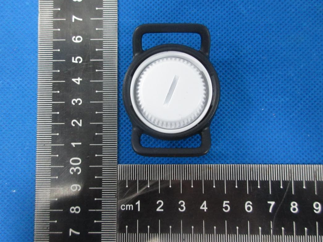
Click to zoom
Application Details
- Equipment Class
- DTS - Digital Transmission System
- Date of Grant
- Oct 15, 2023
- Application Purpose
- Original Equipment
- Date of Application
- Oct 15, 2023
- Equipment Note
- Wireless Safety Key
- Frequency Range
- 2402.00000000 - 2480.00000000
- Company
- Fliteboard Pty Ltd
- Country
- Australia
Documents & Files
Document Text
Text extracted from the exhibit documents filed with the FCC. Open a document above to read the original.
Users Manual
User Guide SERIES 3 COVER 3. Avoid contact with the wings and Flite Jet 5 6 3 4 Flitescooter assembly In ating Flitescooter 5. Keep distance 200m 6. Release the throttle 7. What’s in the box Connect the handlebars to Flitescooter Turn the handlebars upside down and place the Flite Controller wrist strap over the bottom of the handlebars. Carefully slide the wrist strap to the very top by holding onto Flite Controller. With your other hand, lift the latch on the back of the Flite Controller cavity. Place Flite Controller into the handlebar cavity and gently push until you hear it click into place. No relevant for scooter - image will be removed ‘200m’ needs the right font Find Freedom. Take Flite. Important Material Safety Data Sheets fliteboard.com/MSDS Ready to fly post storage checklist fliteboard.com/ readytoflychecklist 6 Month Flitecell Checklist fliteboard.com/ flitecellchecklist Watch our video tutorials at fliteboard.com/video Download the Flite App fliteboard.com/app For the latest version and translations of this guide visit fliteboard.com/support Authorised Flite Service, Resellers and Fliteschools fliteboard.com/locations Flitescooter support fliteboard.com/support Flitescooter contact fliteboard.com/contact Flitescooter User Guide IN ORDER TO OPERATE THE PRODUCT CORRECTLY AND MINIMISE THE CHANCES OF DAMAGE, SERIOUS INJURY OR DEATH, IT IS ESSENTIAL TO READ AND FOLLOW ALL OF THE INSTRUCTIONS AND WARNINGS IN THE USER GUIDE PRIOR TO ASSEMBLY, SETUP OR USE. BY USING A FLITESCOOTER YOU AGREE THAT YOU DO SO AT YOUR OWN RISK. CAUTION: THIS PRODUCT HAS BEEN KNOWN TO DRAMATICALLY IMPROVE YOUR LIFE AND HAPPINESS LEVELS. 6 Safety and Disclaimer 6 Warning 6 Intended use 7 Propulsion system 7 Hydrofoil safety 7 Learning to Flitescooter 8 Important rider safety 10 Flitecell 11 Warranty and Compliance 11 Warranty 11 Repairs 11 Shipping compliance 12 What’s in the box 12 Box 1 Flitescooter and wings 13 Box 2 Flitecell + Box 3 Charger 14 Box 4 Flitescooter eFoil 15 Box 4 Accessories pouch 16 Getting started 17 Charging Flite Controller 18 Flitecell charging procedure 18 Flitecell Indicator Guide 19 Charging Flitecell 20 Flitescooter assembly 22 Connect the eFoil to Flitescooter 23 Installing Flite Jet 24 Connect the fuselage tail 25 Connect the stabiliser wing 26 Connect Flitecell to Flitescooter 27 Download Flite App and update 28 Flite Controller overview 30 Connecting Flite App to Flitescooter 31 Connecting Flite App to Flite Controller 31 Capturing sessions 32 Flite Controller pairing procedure 34 Flite Controller screen guide 38 Turning on Flitecell 39 Connect the handlebars to Flitescooter 40 Flitescooter safety 40 Select a suitable riding location 41 Arming the motor 42 Riding Flitescooter for the first time 44 Flitescooter common mistakes 45 Flitescooter pro tips 45 Foiling through turns 46 Maintenance and storage 47 Flitescooter 48 eFoil system 48 Flite Controller overview 48 Handlebars overview 49 Flitecell 50 Troubleshooting 52 Technical specifications 56 Warranty registration / Details of purchase 57 Maintenance schedule Propulsion system The Flitescooter propulsion system includes a powerful jet. KEEP BODY, FINGERS AND TOES AWAY FROM FLITESCOOTER’S IMPELLER. CONTACT WITH THE IMPELLER CAN CAUSE SERIOUS INJURY OR DEATH. NEVER TOUCH THE IMPELLER IN OR OUTSIDE OF THE WATER. NEVER HANDLE THE IMPELLER WHILE THE FLITECELL IS CONNECTED. ALWAYS USE THE FLITESCOOTER A SAFE DISTANCE FROM OTHER WATERCRAFT, SWIMMERS, SURFERS, DIVERS AND WILDLIFE. NEVER USE FLITESCOOTER IN WATER SHALLOWER THAN 1M OR 3.3FT. HITTING THE BOTTOM AT SPEED CAN CAUSE INJURY AND/OR DAMAGE TO FLITESCOOTER. Hydrofoil safety The Flitescooter hydrofoil system comprises a mast (or strut), a main wing and stabiliser wing. These components include sharp trailing edges and wing tips. Take care not to kick or hit the sharp edges when in the water. FALLING ON THE HYDROFOIL CAN CAUSE SERIOUS INJURY OR DEATH. WE ALWAYS RECOMMEND YOU WEAR APPROPRIATE SAFETY GEAR WHEN FLITESCOOTERING, INCLUDING AN APPROVED IMPACT VEST / PFD AND HELMET. CHECK YOUR LOCAL REGULATIONS TO CONFIRM IMPACT VEST / PFD AND HELMET REQUIREMENTS. REFER TO THE MANUFACTURER’S DOCUMENTATION ON SAFETY, CARE AND MAINTENANCE GUIDELINES FOR YOUR IMPACT VEST / PFD AND HELMET. TAKE CARE TO LEARN STEP BY STEP, FOLLOWING THE INSTRUCTIONS IN THIS GUIDE AND THE FLITESCOOTER VIDEO TUTORIALS AT fliteboard.com/video Learning to Flitescooter We recommend learning to Flitescooter with an instructor at an authorised Fliteschool. Fliteschool locations can be found at fliteboard.com/locations PLEASE VIEW OUR HOW TO FLITESCOOTER VIDEO AT fliteboard.com/video TO LEARN THE PROPER TECHNIQUE AND REVIEW RIDING SAFETY INFORMATION. FLITESCOOTER IS DESIGNED FOR USE IN CALM WATER ONLY. IT IS NOT SUITABLE FOR RIDING BREAKING WAVES IN THE SURF ZONE. RIDERS DO SO AT THEIR OWN RISK. FLITESCOOTER SHOULD NEVER BE RIDDEN NEAR OTHER WATER USERS (INCLUDING SWIMMERS AND SURFERS) OR OFFSHORE FROM SWIMMERS AND SURFERS (IN CASE FLITESCOOTER IS PUSHED TOWARDS SHORE IN A WAVE). FLITESCOOTERING CAN BE EASY WHEN PROPER TECHNIQUE IS APPLIED. INCORRECT TECHNIQUE CAN RESULT IN INJURY OR DAMAGE. Safety and Disclaimer All safety and disclaimer information is subject to change at the sole discretion of Flite. For up-to-date product information visit fliteboard.com/support Warning Failure to operate this product in a safe and responsible manner could result in injury or death to yourself or others and/or damage to the Flitescooter or other’s property. THIS PRODUCT MUST BE OPERATED WITH CAUTION AND COMMON SENSE AND REQUIRES SOME BASIC MECHANICAL ABILITY. FLITESCOOTER IS FOR OPERATION BY ONE PERSON ONLY, SUBJECT TO LOCAL LAWS AND REGULATIONS. DO NOT USE WITH INCOMPATIBLE COMPONENTS OR ALTER THIS PRODUCT IN ANY WAY OUTSIDE OF THE DOCUMENTS PROVIDED BY FLITE. FLITESCOOTER IS NOT A TOY. EXERCISE CAUTION. ACT RESPONSIBLY WHILE OPERATING. CONSIDER THE SAFETY OF YOUR ENVIRONMENT BEFORE OPERATING FLITESCOOTER. DO NOT RIDE I…
Text truncated - open the document above for the full version.
Users Manual
Light blue solidReady to ride Red flashing Alert (high temp, tilt, overcurrent, system error) Blue flashingArmed Blue chasingMotor running Orange flashingDisconnected Flitecell / Controller Orange chasing Searching for new pair Flitecell / Controller Purple solidFlite App connected Purple chasingFlite App data transfer Flitebox lightFlite Controller meaning Searching for new pair Ready to ride + ButtonMode Button Flite Controller pairing procedure 1 Ensure Flitebox power cables are connected to Flitecell. Close the lid and wait for the audible beep indicating the board is switched on. 2 Open the Flitescooter lid and place the base of the Flite Controller on the pairing target of the Flitebox (between the Flitecell cables). Note: With the lid open, the system will shut down after 10 seconds. 3 Once the LED lights change to scrolling orange, remove the Flite Controller from the pairing target and close the lid. 4 Set the controller into pairing mode by holding the + button for 7 seconds until the words 'PRESS MODE TO COMMENCE PAIRING' appear. Then press mode button to confirm. The words 'LOOKING FOR NEW PAIR' will appear. 5 Once paired successfully, the LEDs will change to a light blue colour. 6 Fasten the latches once paired successfully. Troubleshooting: If the lights are not solid blue, or the battery icon on your Flite Controller is crossed out, this indicates that the Flitecell has not paired, and the process needs to be repeated from Step 1. The Magnetic Clip can be used to keep Flitecell activated longer than 10 seconds. Remove once paired. DO NOT HOLD THE FLITE CONTROLLER IN THE PAIRING POSITION FOR MORE THAN 30 SECONDS. HOLDING THE FLITE CONTROLLER IN THIS POSITION WILL PUT THE BOARD INTO SOFTWARE UPDATE. 1 3 4 5 3233 Current Speed / Gear Speed 1.3km/h Gear 1 Pairing required Flite Controller is not paired. Hold plus for 7 seconds until Flite Controller displays LOOKING FOR NEW PAIR. Distance Travelled 6.4kms Remaining 24.7kms Current Speed 23.6km/h Time Elapsed 60mins Remaining 12mins Current speed 23.6km/h Speed Maximum 35.1km/h Average 13.2km/h Current speed 23.6km/h Flite Controller screen guide Motor locked Ready to arm. Flitecell 100% charged Gear set to 1 Jet propulsion selected Motor armed Motor unlocked with 5 seconds to squeeze the throttle trigger. Flitecell charge 50% Disconnected (scrolling) Flite Controller is not connected or under water. Hold plus for 7 seconds until Flite Controller displays LOOKING FOR NEW PAIR. Looking for new pair (scrolling) Flite Controller is looking for a new pair. Battery not paired Repeat pairing process (see page 32). Diagnostics Flitecell kilowatts 1.5 RPM x 1000 = 2,100 ESC Temp 40°C Flitecell Temp 40°C Flitecell Charge 100% Current Speed 23.6km/h Efficiency 60 Wh/km Flitecell charge 100% Current speed 23.6km/h 3435 Motor Cool Down The motor needs to cool down. Flitescooter is limited to low gears for 1 minute to allow motor to cool. High Current Motor Cool Down mode will be activated if power isn’t reduced. Testing Motor To avoid accidental injury, this feature prevents the motor from being turned on fully and any overheating to seals, when the board is on land. High Temp Flitecell is too hot. Ride using low power to allow Flitecell to cool, otherwise Flitecell may shut down. Flitescooter tilted Flitescooter is disabled due to the tilt angle. 50% Flitecell warning Flitecell has 50% (or less) remaining charge. Flitecell charge critical Flitecell charge very low, immediately return to shore. Flitescooter is limited to low gears only to conserve charge. Flite Controller low charge Flite Controller requires charge. Ensure Flite Controller is charged above 50% each ride. Charge remaining Flitecell 98% Flite Controller 66% Flite Controller charging Flite Controller currently at 10% state of charge. Flite Controller screen guide Settings Flitescooter settings can be updated on the Flite App or the Flite Controller. To change settings on the Flite Controller, hold the Mode button until the settings screen is displayed. CONNECTING TO FLITESCOOTER WILL TRANSFER SETTINGS FROM THE APP (E.G. KNOTS AND MILES PER HOUR). PLEASE BE AWARE THAT SPEED READOUT REQUIRES A GPS CONNECTION. IF YOU ARE RIDING WITH POOR GPS SIGNAL YOU MAY NOT BE ABLE TO SEE YOUR CURRENT SPEED. 3637 THE SEAL IS A CRITICAL COMPONENT. IF DAMAGED CONTACT YOUR FLITE AUTHORISED SERVICE PARTNER FOR A REPLACEMENT PART. NEVER RIDE THE BOARD WITH A DAMAGED SEAL. THE FLITECELL AND CABLES ARE WATER RESISTANT; HOWEVER, ALWAYS KEEP FLITECELL, CABLES AND BOARD CAVITY DRY. WATER, ESPECIALLY SALT WATER, CAN ACCELERATE AGEING AND CORROSION. IF YOUR BOARD LEAKS, CHECK SEALS, AND CLEAN COMPONENTS CAREFULLY. SEE PAGE 32 FOR PAIRING FLITE CONTROLLER Turning on Flitecell 1 Make certain nothing is caught in the seal. Carefully close the lid. 2 Twist and lock the two lid latches. 3 A few seconds after the lid is shut in position, you will hear a ‘beep beep beep’ which signifies that the Flitecell and board have automatically turned on. 4 If the external board light is not active, open the lid and ensure the power cables are properly connected, and there are lights on the Flitecell indicating it is switched on. 5 Flitecell will automatically turn off 10 seconds after the lid is opened. 3 1 Connect the fuselage tail Turning on Flitescooter Place the in ated Flitescooter on a clear surface. Locate the handlebar cap and remove by gently pulling up Turn the handlebar lock counterclockwise so that the opening lines up with the handlebar cavity. Insert the handlebars into the handlebar cavity. Turn the handlebar lock clockwise until it stops. This will keep the handlebars locked into place. Flitescootering for the rst time Arming the motor Connect the front wing Connect the stabliser Connect the handlebars to Flitescooter Flitescooter's excellent buoyancy allows you to step on from a dock or pontoon. If you are starting in the water, do step 2 and 3 from the shore, then float your board with the eFoil facing…
Text truncated - open the document above for the full version.
Attestation Statements
To whom it may concern, Ref: Attestation Statements Part 2.911(d) (7) Filing Fliteboard Pty Ltd ("the applicant") certifies that, as of the date of the filing of the application, Fliteboard Pty Ltd appoints Fliteboard USA LLC as a U.S. agent for service of process. Fliteboard Pty Ltd agrees to maintain an agent for no less than one year after it has terminated all marketing and importation or the conclusion of any Commission-related proceeding involving the equipment. Fliteboard USA LLC accepts, as of the date of the filing of the application, the obligation of the designated U.S. agent for service of process. Applicant: Company Name: Fliteboard Pty Ltd Address: 156 Jonson St, Byron Bay NSW 2481, Australia Contact Person: Robert Bell Tel: +61 2 6694 3186 Email: [email protected] Applicants Name: Robert Bell Title: Global Managing Director Signature: Designated U.S. Agent Information: Name: Fliteboard USA LLC FRN: 0034282780 Address: 860 Harbor Way South, Suite A, Richmond CA 94804, USA Contact Person: Alex Hawkins Tel: +1 (949) 467 4474 Email: [email protected] US Agent’s Name: Alex Hawkins Title: Managing Director USA Signature: 26 September 2023 Federal Communications Commission Authorization and Evaluation Division 7435 Oakland Mills Road Columbia, MD 21046 USA Doc ID: 8c2bcb625c789ab952ea4855106655e82401241e Audit trail Title File name Document ID Audit trail date format Status Powered by Sign Sign 20230926 FCC Agent for Service of process letter 20230926 FCC Agen...rocess Letter.pdf 8c2bcb625c789ab952ea4855106655e82401241e DD / MM / YYYY Signed 26 / 09 / 2023 14:23:56 UTC+10 Sent for signature to Alex Hawkins ([email protected]) and Robert Bell ([email protected]) from [email protected] IP: 203.19.70.80 28 / 09 / 2023 13:58:36 UTC+10 Viewed by Robert Bell ([email protected]) IP: 122.106.105.238 28 / 09 / 2023 13:58:58 UTC+10 Signed by Robert Bell ([email protected]) IP: 122.106.105.238 29 / 09 / 2023 06:28:48 UTC+10 Viewed by Alex Hawkins ([email protected]) IP: 73.241.247.223 29 / 09 / 2023 06:29:07 UTC+10 Signed by Alex Hawkins ([email protected]) IP: 73.241.247.223 The document has been completed. 29 / 09 / 2023 06:29:07 UTC+10
Attestation Statements
Fliteboard Pty Ltd The information provided in this letter is based on the referenced rule parts of Title 47 of the CFR as well as KDB 986446 D01. Federal Communications Commission Authorization and Evaluation Division Equipment Authorization Branch 7435 Oakland Mills Road Columbia, MD 21046 10/10/2023 To whom it may concern: We, [Fliteboard Pty Ltd], hereby certify that the equipment for which authorization is sought (FCC ID: 2BB7A-WSK1) is not “covered” equipment prohibited from receiving an equipment authorization pursuant to § 2.903 of the FCC rules. We also certify that, as of the date of the filing of the application, we are not identified on the Covered List (https://www.fcc.gov/supplychain/coveredlist) as an entity producing “covered” equipment. By signing this form, we confirm the above and that we are aware of the application requirements listed under § 2.911(b) and (d)(5) and (6). Sincerely, Signature [Name] Sam T Bolton [Title] Principal Electronics Engineer [Company] Fliteboard Pty Ltd 62_[model] CoveredEqu_2.911(d)(5)(i) and (ii) - U, V02
External Photos
ATTACHMENT PHOTOGRAPHS OF EUT Photo 1 Photo 2 Photo 3 Photo 4 Photo 5 Photo 6
ID Label/Location Info
2.247 mm 10.0 mm
Internal Photos
Photo 1 Photo 2 Photo 3 Photo 4 Photo 5 Photo 6 ANT Photo 7
RF Exposure Info
FCC ID: 2BB7A-WSK1 Portable device According to §15.247(e)(i) and §1.1307(b)(1), systems operating under the provisions of this section shall be operated in a manner that ensures that the public is not exposed to radio frequency energy level in excess of the Commission’s guidelines. According to KDB447498 D01 General RF Exposure Guidance V06 The 1-g SAR and 10-g SAR test exclusion thresholds for 100 MHz to 6 GHz at test separation distances ≤ 50 mm are determined by: [(max. power of channel, including tune-up tolerance, mW)/(min. test separation distance, mm)]·[√f(GHZ)] ≤ 3.0 for 1-g SAR and ≤ 7.5 for 10-g extremity SAR, where: • f(GHZ) is the RF channel transmit frequency in GHz • Power and distance are rounded to the nearest mW and mm before calculation • The result is rounded to one decimal place for comparison When the minimum test separation distance is < 5 mm, a distance of 5 mm is applied to determine SAR test exclusion. BLE: Modulation Channel Freq. (GHz) Conduct ed power (dBm) Conducte d power (mW) Tune-up power (dBm) Max tune-up power (dBm) Max tune-up power (mW) Distance (mm) Result calculatio n SAR Exclusion threshold SAR test exclusion 2.4022.171.652±132.00<50.618473.00YES 2.4401.891.552±132.00<50.623343.00YES 2.4801.251.332±132.00<50.628433.00YES 2.4022.241.672±132.00<50.618473.00YES 2.4401.931.562±132.00<50.623343.00YES 2.4801.271.342±132.00<50.628433.00YES BLE(1M) BLE(2M) Conclusion: For the max result : 0.62843 ≤ 3.0 for 1g SAR, SAR is not required. Signature: Date: 10/11/2023 NAME AND TITLE (Please print or type): Alex li /Manager COMPANY (Please print or type): Shenzhen NTEK Testing Technology Co., Ltd./ 1/F, Building E, Fenda Science Park, Sanwei Community, Xixiang Street Bao’an District, Shenzhen P.R. China.
Test Report
Report No.: S23081407605001 Version.1.3 Page 1 of 54 RADIO TEST REPORT FCC ID: 2BB7A-WSK1 Product: Wireless Safety Key Trade Mark: Model No.: WSK1 Family Model: N/A Report No.: S23081407605001 Issue Date: Aug 25, 2023 Prepared for Fliteboard Pty Ltd 156 Jonson Street, Byron Bay NSW 2481, Australia Prepared by Shenzhen NTEK Testing Technology Co., Ltd. 1/F, Building E, Fenda Science Park, Sanwei Community,Xixiang Street Bao’an District, Shenzhen 518126 P.R. China Tel:400-800-6106,0755-2320 0050 / 2320 0090 Website: http://www.ntek.org.cn Report No.: S23081407605001 Version.1.3 Page 2 of 54 TABLE OF CONTENTS 1 TEST RESULT CERTIFICATION ...................................................................................................................... 3 2 SUMMARY OF TEST RESULTS ......................................................................................................................... 4 3 FACILITIES AND ACCREDITATIONS ............................................................................................................. 5 3.1 FACILITIES..................................................................................................................................................... 5 3.2 LABORATORY ACCREDITATIONS AND LISTINGS ................................................................................. 5 3.3 MEASUREMENT UNCERTAINTY ............................................................................................................... 5 4 GENERAL DESCRIPTION OF EUT .................................................................................................................. 6 5 DESCRIPTION OF TEST MODES ..................................................................................................................... 8 6 SETUP OF EQUIPMENT UNDER TEST ........................................................................................................... 9 6.1 BLOCK DIAGRAM CONFIGURATION OF TEST SYSTEM ....................................................................... 9 6.2 SUPPORT EQUIPMENT............................................................................................................................... 10 6.3 EQUIPMENTS LIST FOR ALL TEST ITEMS .............................................................................................. 11 7 TEST REQUIREMENTS .................................................................................................................................... 13 7.1 CONDUCTED EMISSIONS TEST ............................................................................................................... 13 7.2 RADIATED SPURIOUS EMISSION ............................................................................................................ 15 7.3 6DB BANDWIDTH ....................................................................................................................................... 24 7.4 DUTY CYCLE ............................................................................................................................................... 25 7.5 PEAK OUTPUT POWER .............................................................................................................................. 27 7.6 POWER SPECTRAL DENSITY ................................................................................................................... 28 7.7 CONDUCTED BAND EDGE MEASUREMENT......................................................................................... 30 7.8 SPURIOUS RF CONDUCTED EMISSIONS................................................................................................ 31 7.9 ANTENNA APPLICATION .......................................................................................................................... 32 8 TEST RESULTS ................................................................................................................................................... 33 8.1 1M .................................................................................................................................................................. 33 8.2 2M .................................................................................................................................................................. 44 Report No.: S23081407605001 Version.1.3 Page 3 of 54 1 TEST RESULT CERTIFICATION Applicant’s name .................... : Fliteboard Pty Ltd Address .................................. : 156 Jonson Street, Byron Bay NSW 2481, Australia Manufacturer's Name ............. : Fliteboard Pty Ltd Address ................................. : 156 Jonson Street, Byron Bay NSW 2481, Australia Product description Product name ......................... : Wireless Safety Key Model and/or type reference . : WSK1 Family Model .......................... : N/A Test Sample Number .............. : S230814076006 Measurement Procedure Used: APPLICABLE STANDARDS APPLICABLE STANDARD/ TEST PROCEDURE TEST RESULT FCC 47 CFR Part 2, Subpart J FCC 47 CFR Part 15, Subpart C KDB 174176 D01 Line Conducted FAQ v01r01 ANSI C63.10-2013 KDB 558074 D01 15.247 Meas Guidance v05r02 Complied This device described above has been tested by Shenzhen NTEK Testing Technology Co., Ltd., and the test results show that the equipment under test (EUT) is in compliance with the FCC requirements. And it is applicable only to the tested sample identified in the report. This report shall not be reproduced except in full, without the written approval of Shenzhen NTEK Testing Technology Co., Ltd., this document may be altered or revised by Shenzhen NTEK Testing Technology Co., Ltd., personnel only, and shall be noted in the revision of the document. The test results of this report relate only to the tested sample identified in this report. Date of Test : Aug 14, 2023 ~ Aug 25, 2023 Testing Engineer : (Mary Hu) Authorized Signatory : (Alex Li) Report No.: S23081407605001 Version.1.3 Page 4 of 54 2 SUMMARY OF…
Text truncated - open the document above for the full version.
Test Report
version01 Fliteboard Pty Ltd Declaration concerning Antenna Specification It is hereby declared that the product Model No.: MTB01 FCC ID: 2ABU6-MTB01 fulfills the requirement in FCC test relating to the antenna type. The device specified above confirms to the FCC recommendations for PCB Antenna antenna type(s) described below: Model No. of antenna: ANT-2.4G-16 Type of antenna: PCB Antenna Gain of the antenna: -4.15 dBi Frequency range: 2402-2480 MHz The mounting of the antenna is fixed to the radio module and no other antenna should be used. Company name: Fliteboard Pty Ltd Address: 156 Jonson Street, Byron Bay NSW 2481, Australia City: Byron Bay ZIP / Postal code: 2481 Country: Australia Name: Sam T Bolton Date: 12/10/2023 Signature:
Test Report
深圳云里物里科技股份有限公司 产品天线测试报告(TheAntennaTestReport) Y-YB-CR-115V001密级:绝密/confidentiality 第1页 共4页 AntennaCoding:ANT-2.4G-16 AntennaType:PCB onboardAntenna Modelof the DUT : WSK1 AntennaManufacturer:ShenzhenMinewTechnologiesCo., Ltd. 1、TechnicalSpecification ElectricalSpecifications FrequencyRange(MHz) 2402-2480 InputImpedance(Ω) 50 ReturnLoss ( dB )< -10 VSWR < 2 PeakGain(dBi) -4.15 PolarizationTypeLinearpolarization MechanicalSpecifications AntennaSize (mm)14.95*4.78 RadiatorCuprum 2、The shapeand size of the antenna 深圳云里物里科技股份有限公司 产品天线测试报告(TheAntennaTestReport) Y-YB-CR-115V001密级:绝密/confidentiality 第2页共4页 3、Theresultofthetest 3.1TestEnvironment 3.2GainandEfficiency 深圳云里物里科技股份有限公司 产品天线测试报告(TheAntennaTestReport) Y-YB-CR-115V001密级:绝密/confidentiality 第3页共4页 3.33D PolarPlot 2440MHz 3.42DRadiationPattern (1)E1,XZPlane,phi=0 深圳云里物里科技股份有限公司 产品天线测试报告(TheAntennaTestReport) Y-YB-CR-115V001密级:绝密/confidentiality 第4页共4页 (2)E2,YZPlane,phi=90° (3)H,XYplane,theta=90°
Test Setup Photos
Radiated Measurement Photos
Contact Information
Applicant
Sam Bolton(Principal Electronics Engineer)
Test Firm
Shenzhen NTEK Testing Technology Co., Ltd.Alex Li
[email protected]+86-755-6115-9384
Technical Specifications
| # | Rule Parts | Frequency Range | Power Output |
|---|---|---|---|
| 1 | 15C | 2.40 GHz - 2.48 GHz | 1.70 mW |