2BBAE-D10PLUSMotorcycle Dash-cam
Shenzhen Shendu Software Co., Ltd.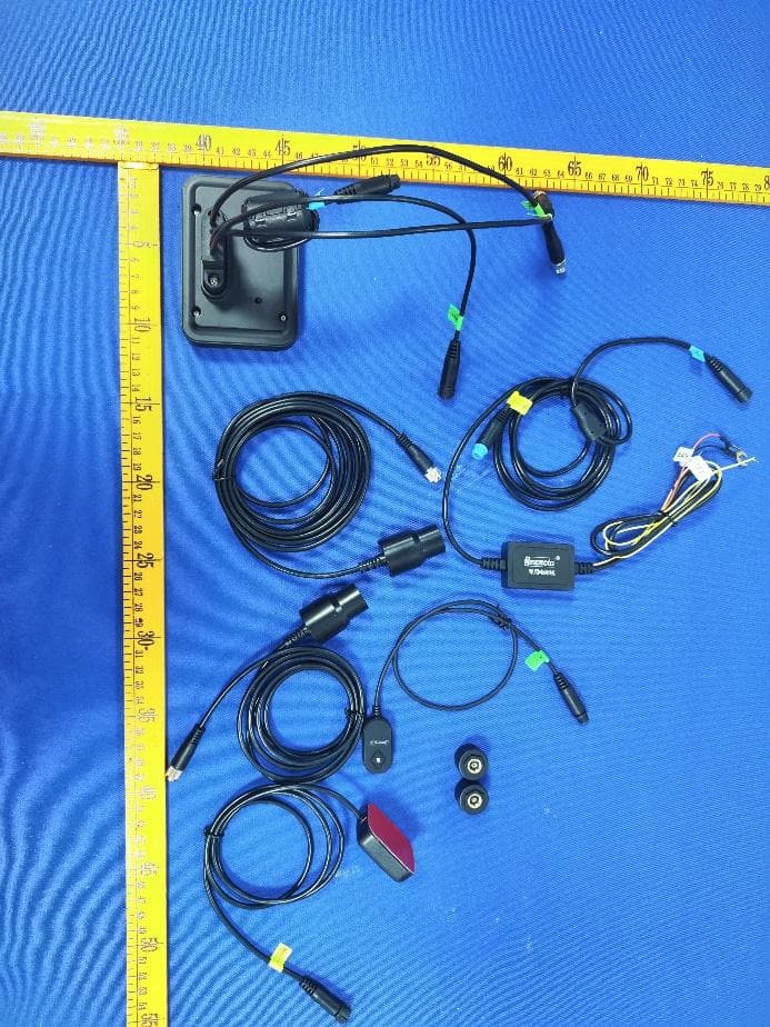
Click to zoom
Application Details
- Equipment Class
- DTS - Digital Transmission System
- Date of Grant
- May 28, 2023
- Application Purpose
- Original Equipment
- Date of Application
- May 28, 2023
- Equipment Note
- Motorcycle Dash-cam
- Frequency Range
- 2412.00000000 - 2462.00000000
- Country
- China
Documents & Files
Document Text
Text extracted from the exhibit documents filed with the FCC. Open a document above to read the original.
Users Manual
Motorcycle Dash-cam D10Plus User Manual Explore the world on two wheels with Deepmoto Your trusted companion for all your motorcycle adventures power D E E P M O TO Fast & Furious CONTENTS Safety Instructions for Use .................................................. 4 Dash-cam D10Plus Features ................................................ 6 Accessories ......................................................................... 10 Installation Guide ................................................................ 13 1. Pre-installation Preparation ....................................................................13 2. Installation ..............................................................................................13 Function Introduction ......................................................... 18 1. Dash-cam Buttons and Operation Introduction ......................................18 2. Dash-cam Interface Introduction ............................................................20 3. Remote Function Introduction ................................................................23 4. Menu Interface and Function Introduction ..............................................24 Tire Pressure Installation And Function Introduction ...... 28 1.Install the Tire Pressure Sensor ..............................................................28 2.Tire Pressure Equipment Matching Function ...........................................29 App Function Introduction ................................................. 30 1. App Introduction .....................................................................................30 2. App Installation Method ..........................................................................30 3. App WiFi Connection..............................................................................31 4. App Function Introduction ......................................................................32 5. System Upgrade ....................................................................................36 FAQ Guide ........................................................................... 37 1.Dash-cam Host-related Issues ................................................................37 2.Camera and Video Related Issues ..........................................................38 3.Application and WiFi Related Issues .......................................................39 Product Parameters ............................................................ 40 4 5 Safety Instructions for Use Dash-cam D10Plus The installation of this product requires a certain amount of hands- on ability. If the customer is not good at installing it by himself, it is recommended to go to the local car dealership and seek professional guidance for installation. Please turn off the power of the motorcycle before installation, and restart the motorcycle after the installation is completed. The motorcycle power box needs to be opened during installation, please prepare the corresponding tools by yourself. The installation process is not complicated, please check the installation guide carefully and connect each accessory with the dash-cam. Motorcycle models are different. Customers can choose a suitable location to install the host, camera, remote, power source, and GPS modules according to their own models. When installing, please pay attention to the socket of the cable, and do not use too much force to damage the interface. Please arrange the wiring reasonably, do not squeeze or fold, so as not to damage the cable. When installing GPS, try to avoid installing it in a place surrounded by metal, which may affect GPS signal reception. The camera is fully sealed and waterproof. Avoid using solvents such as alcohol and asphalt cleaning agent to contact the lens, so as not to damage the waterproof layer. Do not wash the dash-cam with a high-pressure water gun for a long time to prevent water from entering the host. When the dash-cam is turned on, do not insert or remove the TF card to avoid damage to the TF card. 1 2 3 4 5 6 7 8 9 Do not cut off the power when the system firmware is being upgraded online. The safety voltage of this dash-cam is 36V, which can be applied to all motorcycle types (usually the voltage of the motorcycle battery is 12V). However, for some electric motorcycles, the battery voltage is as high as 60V or more, which has exceeded the voltage of the dash-cam, and may burn out the dash-cam host. If it is to be installed and used on an electric motorcycle, a voltage converter is required. 10 11 If you have any questions, please send email to us, we will answer you in time. Customer service email: [email protected] 6 7 Dash-cam D10Plus FeaturesDash-cam D10Plus Features Cortex A7 Dual-core Intelligent Chip6 Glass Optical Lens + IR Filter Connect The ACC Power Supply To Keep the Video Recording Synchronization At All Times Front and Rear Dual Cameras F1.6 Large Aperture 150° Wide Angle 2GB High-capacity RAM Sony IMX307 Image Sensor Support Up to 256GB TF Card Full HD 1080P/30 Frames Starlight Night Vision EIS Electronic Image Stabilization With stronger performance and lower power consumption, brings you a more enjoyable user experience. Makes your device run more smoothly, enabling you to enjoy an efficient user experience. Self-bandwidth dynamic technology, backlight display is clearer . Allowing you to record any content you want and store more precious memories. Chip Camera REC 8 9 Dash-cam D10Plus FeaturesDash-cam D10Plus Features Dash-cam Host Special Features 1:10 All Metal MaterialBending Warning Vibration Sensor Altitude Air Pressure Take Pictures With One Key GPS Track Playback Exclusive APP 3-inch IPS Full-view High-definition Screen Elegant design, black body, red logo, durable, better heat dissipation, better quality. Monitor the motorcycle's inclination angle, speeding around the curve, and escort for safety. Monitor the vibration, automatically lock the video when t…
Text truncated - open the document above for the full version.
External Photos
FCCID:2BBAE-D10PLUS FCCID:2BBAE-D10PLUS FCCID:2BBAE-D10PLUS FCCID:2BBAE-D10PLUS
Internal Photos
FCCID:2BBAE-D10PLUS FCCID:2BBAE-D10PLUS FCCID:2BBAE-D10PLUS FCCID:2BBAE-D10PLUS FCCID:2BBAE-D10PLUS ANT
RF Exposure Info
ReportNo.:PTC23040608701E-FC02 Page1of7 FCCTESTREPORT FCCID:2BBAE-D10PLUS Product:MotorcycleDash-cam ModelName:D10Plus SerialModel:D10A,D20B,D20Pro Brand:DEEPMOTO ReportNo.:PTC23040608701E-FC02 Preparedfor ShenzhenShenduSoftwareCo.,Ltd. 308,BuildingA,WenleIndustrialZone,LongzhuCommunity,XixiangStreet,BaoanDistrict, Shenzhen Preparedby PreciseTesting&CertificationCo.,Ltd. Building1,No.6,TongxinRoad,DongchengStreet,Dongguan,Guangdong,China. ReportNo.:PTC23040608701E-FC02 Page2of7 TESTRESULTCERTIFICATION Applicant’sname:ShenzhenShenduSoftwareCo.,Ltd. Address: 308,BuildingA,WenleIndustrialZone,LongzhuCommunity, XixiangStreet,BaoanDistrict,Shenzhen Manufacture'sname:ShenzhenShenduSoftwareCo.,Ltd. Address: 308,BuildingA,WenleIndustrialZone,LongzhuCommunity, XixiangStreet,BaoanDistrict,Shenzhen Productname:MotorcycleDash-cam Modelname:D10Plus SerialModel:D10A,D20B,D20Pro Testprocedure:FCCCFR47Part1.1307(b)(1) TestDate:May.05,2023toMay.18,2023 DateofIssue:May.29,2023 TestResult:PASS ThisdevicedescribedabovehasbeentestedbyPTC,andthetestresultsshowthatthe equipmentundertest(EUT)isincompliancewiththeFCCrequirements.Anditisapplicable onlytothetestedsampleidentifiedinthereport. Thisreportshallnotbereproducedexceptinfull,withoutthewrittenapprovalofPTC,this documentmaybealteredorrevisedbyPTC,personalonly,andshallbenotedinthe revisionofthedocument. TestEngineer: SimonPu/Engineer TechnicalManager: RonnieLiu/Manager ReportNo.:PTC23040608701E-FC02 Page3of7 Contents Page 2TESTSUMMARY...............................................................................................................................................4 3GENERALINFORMATION..............................................................................................................................5 3.1GENERALDESCRIPTIONOFE.U.T..........................................................................................................5 4RFEXPOSURE..................................................................................................................................................6 4.1REQUIREMENTS........................................................................................................................................6 4.2THEPROCEDURES/LIMIT........................................................................................................................6 4.3MPECALCULATIONMETHOD..................................................................................................................7 4.4TESTRESULT...........................................................................................................................................7 ReportNo.:PTC23040608701E-FC02 Page4of7 2TestSummary TestItemsTestRequirementResult MaximumPermissibleExposure (ExposureofHumanstoRFFields) 15.247(i)PASS Remark: N/A:NotApplicable ReportNo.:PTC23040608701E-FC02 Page5of7 3GeneralInformation 3.1GeneralDescriptionofE.U.T. ProductName : MotorcycleDash-cam ModelName : D10Plus Additionalmodel : D10A,D20B,D20Pro Modeldifference:Differentmodelnames Specification:802.11b/g/nHT20 OperationFrequency:2412-2462MHzfor802.11b/g/n(HT20) NumberofChannel : 11channelsfor802.11b/g/n(HT20) TypeofModulation : DSSSwithDBPSK/DQPSK/CCKfor802.11b; OFDMwithBPSK/QPSK/16QAM/64QAMfor802.11g/n; Antennainstallation : FPCantenna AntennaGain : 0.65dBi Powersupply : AdapterModel:Dash-camPowerSupplyD10Plus Input:DC9-36V Output:DC5V HardwareVersion:D10A_MAIN_V30230516 SoftwareVersion:D10Plus-230630-V2.05 ReportNo.:PTC23040608701E-FC02 Page6of7 4RFExposure TestRequirement :FCCPart1.1307(b)(1) EvaluationMethod :KDB447498D01GeneralRFExposureGuidancev06 4.1Requirements Systemsoperatingundertheprovisionsofthissectionshallbeoperatedinamannerthatensuresthat thepublicisnotexposedtoradiofrequencyenergylevelsinexcesslimitformaximumpermissible exposure.Inaccordancewith47CFRFCCPart2SubpartJ,section2.1091thisdevicehasbeen definedasamobiledevicewherebyadistanceof0.2mnormallycanbemaintainedbetweentheuser andthedevice. 4.2Theprocedures/limit (A)LimitsforOccupational/ControlledExposure FrequencyRangeElectricFieldMagneticFieldPowerDensity(S)AveragingTime 0.3-3.06141.63(100)*6 3.0-301842/f4.89/f(900/f)*6 30-30061.40.1631.06 300-1500F/3006 1500-100,00056 (B)LimitsforGeneralPopulation/UncontrolledExposure FrequencyRangeElectricFieldMagneticFieldPowerDensity(S)AveragingTime 0.3-1.346141.63(100)*30 1.34-30824/f2.19/f(180/f)*30 30-30027.50.0730.230 300-1500F/150030 1500-100,0001.030 Note:f=frequencyinMHz;*Plane-waveequivalentpowerdensity ReportNo.:PTC23040608701E-FC02 Page7of7 4.3MPECalculationMethod E(V/m) = d GP30 PowerDensity:Pd(W/m²) = 377 2 E E = Electricfield(V/m) P=PeakRFoutputpower(W) G=EUTAntennanumericgain(numeric) d=Separationdistancebetweenradiatorandhumanbody(m) Theformulacanbechangedto Pd = 2 377 30 d GP θφ FromthepeakEUTRFoutputpower,theminimummobileseparationdistance,d=0.2m,aswellas thegainoftheusedantenna,theRFpowerdensitycanbeobtained 4.4TestResult Mode Antenna Gain (numeric) Max.Peak OutputPower (dBm) Tuneup tolerance (dBm) MaxTuneUp Power(mW) PowerDensity (mW/cm2) LimitofPower Density (mW/cm2) Result 24121.1621.5721.57±1180.7174130.0417571Pass ******THEENDREPORT******
Test Report
ResearchanddevelopmentofShenzhenRuifengElectronicTechnologyCo.,LTD CompanyAddress:4thFloor,BuildingB5,XinfuIndustrialPark,ChongqingRoad,FuyongTown,Bao'anDistrict, ShenzhenTEL:0755-27211658FAX:0755-29485750 AcknowledgmentLetter SPECIFICATIONFORAPPROVAL ApprovalustomerApproval PreparedByCheckedByApprovalByCheckedByApprovalBy Signature Huang Zongbao FuXuerongXiaChenglei Date2023.5.102023.5.102023.5.10 hangeLog VersionChangeDescriptionPersoninChargeApprovalByDate CustomerNameDeepTechnology CustomerProject Name D10SProjectNameD10S CustomerP/NSDCP/N WF3163B-0812M-80 Band WIFI2.4G/BT Version A0 DesignerInformation RFEngineerFuXuerongR&DDiretorXiaChenglei MEEngineerHuangZongbao ResearchanddevelopmentofShenzhenRuifengElectronicTechnologyCo.,LTD CompanyAddress:4thFloor,BuildingB5,XinfuIndustrialPark,ChongqingRoad,FuyongTown,Bao'anDistrict, ShenzhenTEL:0755-27211658FAX:0755-29485750 Catalogue No.ItemPageNo. 1DrawingorProductImage3 2DimensionsTestReport4 3RFPerformanceTestReport5-7 4ReliabilityTestReport18 5PackageDocument9 6RoHSControllistforSample10 7InstallWizardorOther10 ResearchanddevelopmentofShenzhenRuifengElectronicTechnologyCo.,LTD CompanyAddress:4thFloor,BuildingB5,XinfuIndustrialPark,ChongqingRoad,FuyongTown,Bao'anDistrict, ShenzhenTEL:0755-27211658FAX:0755-29485750 DrawingorProductImage S D C D 1 0 S W F 李 瑶 娜 W F 3 1 6 3 B - 0 8 1 2 M - 8 0 D 1 0 S X . X ± 0 . 5 X . X X ± 0 . 2 X X X . ± 1 0 . 0 X X . ± 5 . 0 X . ± 2 . 0 1 8 0 1 注 : 6 0 m m 以 内 的 线 材 , 若 无 客 户 要 求 则 默 认 端 子 头 朝 下 ResearchanddevelopmentofShenzhenRuifengElectronicTechnologyCo.,LTD CompanyAddress:4thFloor,BuildingB5,XinfuIndustrialPark,ChongqingRoad,FuyongTown,Bao'anDistrict, ShenzhenTEL:0755-27211658FAX:0755-29485750 SampleDimensionsTestReport TestDate2023.5.10SampleQty.3Inspector XuYanfang DimensionNo.StandardSample1Sample2Sample3Pass/NG ①length18±0.2mm181818 Pass ②width22±0.2mm222222 Pass ③ thickness 0.1±0.03mm0.10.10.1 Pass ④Linelength100±2mm100101100 Pass ⑤ ⑥ ⑦ ConclusionPASS Inspector&Date XuYanfang2023.5.10 Approval&Date ResearchanddevelopmentofShenzhenRuifengElectronicTechnologyCo.,LTD CompanyAddress:4thFloor,BuildingB5,XinfuIndustrialPark,ChongqingRoad,FuyongTown,Bao'anDistrict, ShenzhenTEL:0755-27211658FAX:0755-29485750 RFPerformanceTestReport AntennaTestEquipmentIntroduction TestofantennainputcharacteristicsusingAgilentE5071CandAgilent5062Avectornetwork analyzer;Theradiationpatternoftheantennaaretestedusingtheguangping3DnearfieldAnechoicChamber, andtheinstrumentisusedtoagilent8960E5515andAgilentE4438C.Thetestcoordinatesofthedarkroom areasfollows: 1.S11Parameter-VSWR MeasuringMethodisa50Ωcoaxialcableisconnectedtotheantenna.Thenthiscableisconnectedtoanetworkanalyzerto measuretheS11parameter,Keepingthisfixtureawayfrommetalatleast20cm. ResearchanddevelopmentofShenzhenRuifengElectronicTechnologyCo.,LTD CompanyAddress:4thFloor,BuildingB5,XinfuIndustrialPark,ChongqingRoad,FuyongTown,Bao'anDistrict, ShenzhenTEL:0755-27211658FAX:0755-29485750 S11Parameter-VSWR 2. AntennaMatchingNetwork frequency ( MHZ ) 2400 24502500 standing-waveratio 21.31.4 ResearchanddevelopmentofShenzhenRuifengElectronicTechnologyCo.,LTD CompanyAddress:4thFloor,BuildingB5,XinfuIndustrialPark,ChongqingRoad,FuyongTown,Bao'anDistrict, ShenzhenTEL:0755-27211658FAX:0755-29485750 3.Gain&Efficiency Frequency(MHz)Efficiency(%)PeakGAIN(dBi) 240030.260.58 245031.950.65 250031.18-0.13 ResearchanddevelopmentofShenzhenRuifengElectronicTechnologyCo.,LTD CompanyAddress:4thFloor,BuildingB5,XinfuIndustrialPark,ChongqingRoad,FuyongTown,Bao'anDistrict, ShenzhenTEL:0755-27211658FAX:0755-29485750 ReliabilityTestReport TestDate2023.5.10SampleQty.3Inspector XuYanfang TestItemRequirement testing equipment Sample1Sample2Sample3PASS/NG high temperature storage Exposeto+85°Cfor 24hours,recoverfor 2hours,andconduct testing Constant temperature andhumidity box OKOKOKPass low temperature storage Exposeto-40°Cfor 24hours,recoverfor 2hours,andperform testing Constant temperature andhumidity box OKOKOKPass High temperature operation Poweredonfor24 hoursat+60°C Constant temperature andhumidity box OKOKOKPass Low temperature operation Poweredonfor24 hoursat-20°C Constant temperature andhumidity box OKOKOKPass Saltspray test (5士0.5)%sodium chloride、pHValue is6.5~7.2, Temperatureof experimental chamber(35±2)°C □24H☑48H Saltspray testing machine OKOKOKPass Connector rivetingand pulling force 1.13Wirediameter≥ 10N 0.81Wirediameter≥ 8N RG174≥60N RG178≥50N Push-pull forcegauge ≥10N≥10N≥10NPass Conclusion Pass Inspector& Date XuYanfang2023.5.10 Approval&D ate ResearchanddevelopmentofShenzhenRuifengElectronicTechnologyCo.,LTD CompanyAddress:4thFloor,BuildingB5,XinfuIndustrialPark,ChongqingRoad,FuyongTown,Bao'anDistrict, ShenzhenTEL:0755-27211658FAX:0755-29485750 ProductROHSCompositionDeclarationForm InstallWizard orOther setupscript: Take1PCSofproduct,tearoffthereleasepaperonthebackoftheFPCbyhand,and thenaligntheFPCpositioningholepositionwiththeshellpositioningholeposition (positioningribpositionorpositioningline),andattachitflattotheshell,asshown inthefollowingfigure: Installationprocessprecautions: □EnsurethattheFPCisfullyattachedtothehousingafterpastingtheantenna; □Alignthepositioningholewiththepositionofthecasingpositioningcolumn; □AlignFPCedgewithshelledge; □WhenattachingtheterminaltothePCBAendofthemotherboard,pleasefirstalign theterminalsandthensnapthemvertically; □Whendisassemblingantennaterminals,itisnecessarytouseatool(suchasaspecial prybar)toverticallylifttheterminalsandnotdirectlypull thewiresfordisassembly produc tname Unifo rm mater ial Harmfulsubstancecontent(PPM) HStestreportnumber DateofHStest report PbCdHgCrBr WIFI& BT anten na FPC NDNDNDNDND UNIB21042707HR-01 2023.5.10 NDNDNDNDND NDNDNDNDND NDNDNDNDND NDNDNDNDND wire rod NDNDNDNDND NDNDNDNDND NDNDNDNDND termin NDNDNDNDND ResearchanddevelopmentofShenzhenRuifengElectronicTechnologyCo.,LTD CompanyAddress:4thFloor,BuildingB5,XinfuIndustrialPark,ChongqingRoad,FuyongTown,Bao'anDistrict, ShenzhenTEL:0755-27211658FAX:0755-294…
Text truncated - open the document above for the full version.
Test Report
Page 1 of 58 FCCTESTREPORT FCCID:2BBAE-D10PLUS Product:MotorcycleDash-cam ModelName:D10Plus SerialModel:D10A,D20B,D20Pro Brand:DEEPMOTO ReportNo.:PTC23040608701E-FC01 Preparedfor ShenzhenShenduSoftwareCo.,Ltd. 308,BuildingA,WenleIndustrialZone,LongzhuCommunity,XixiangStreet,BaoanDistrict, Shenzhen Preparedby PreciseTesting&CertificationCo.,Ltd. Building1,No.6,TongxinRoad,DongchengStreet,Dongguan,Guangdong,China. ReportNo.:PTC23040608701E-FC01 Page 2 of 58 1TESTRESULTCERTIFICATION Applicant’sname:ShenzhenShenduSoftwareCo.,Ltd. Address: 308,BuildingA,WenleIndustrialZone,LongzhuCommunity,Xixiang Street,BaoanDistrict,Shenzhen Manufacture'sname:ShenzhenShenduSoftwareCo.,Ltd. Address: 308,BuildingA,WenleIndustrialZone,LongzhuCommunity,Xixiang Street,BaoanDistrict,Shenzhen Productname:MotorcycleDash-cam Modelname:D10Plus SerialModel:D10A,D20B,D20Pro Standards:FCCCFR47Part15Section15.247 Testprocedure:ANSIC63.10:2013 TestDate:May.05,2023toMay.18,2023 DateofIssue:May.29,2023 TestResult:Pass ThisdevicedescribedabovehasbeentestedbyPTC,andthetestresultsshowthattheequipmentunder test(EUT)isincompliancewiththeFCCrequirements.Anditisapplicableonlytothetestedsample identifiedinthereport. Thisreportshallnotbereproducedexceptinfull,withoutthewrittenapprovalofPTC,thisdocumentmaybe alteredorrevisedbyPTC,personalonly,andshallbenotedintherevisionofthedocument. TestEngineer: SimonPu/Engineer TechnicalManager: RonnieLiu/Manager ReportNo.:PTC23040608701E-FC01 Page 3 of 58 Contents Page 1TESTRESULTCERTIFICATION...............................................................................................................................2 2TESTSUMMARY..........................................................................................................................................................5 3GENERALINFORMATION..........................................................................................................................................6 3.1GENERALDESCRIPTIONOFE.U.T.....................................................................................................................6 3.2CHANNELLIST.....................................................................................................................................................7 3.3TESTSITE............................................................................................................................................................8 4EQUIPMENTDURINGTEST......................................................................................................................................9 4.1EQUIPMENTSLIST...............................................................................................................................................9 4.2MEASUREMENTUNCERTAINTY.........................................................................................................................11 4.3DESCRIPTIONOFSUPPORTUNITS...................................................................................................................12 5CONDUCTEDEMISSION..........................................................................................................................................13 5.1E.U.T.OPERATION............................................................................................................................................13 5.2EUTSETUP.......................................................................................................................................................13 5.3TESTSET-UP(BLOCKDIAGRAMOFCONFIGURATION).................................................................................14 5.4MEASUREMENTPROCEDURE............................................................................................................................14 5.5CONDUCTEDEMISSIONLIMIT...........................................................................................................................14 5.6MEASUREMENTDESCRIPTION..........................................................................................................................14 5.7CONDUCTEDEMISSIONTESTRESULT.............................................................................................................14 6RADIATEDSPURIOUSEMISSIONS......................................................................................................................15 6.1EUTOPERATION...............................................................................................................................................15 6.2TESTSETUP......................................................................................................................................................16 6.3SPECTRUMANALYZERSETUP..........................................................................................................................17 6.4TESTPROCEDURE.............................................................................................................................................18 6.5SUMMARYOFTESTRESULTS...........................................................................................................................19 7CONDUCTEDSPURIOUSEMISSION....................................................................................................................26 7.1TESTPROCEDURE.............................................................................................................................................26 7.2TESTSETUP......................................................................................................................................................26 7.3TESTRESULT....................................................................................................................................................26 ReportNo.:PTC23040608701E-FC01 Page 4 of 58 8BANDEDGEMEASUREMENT...........................................................................................................…
Text truncated - open the document above for the full version.
Test Report
ReportNo.:PTC23040608701E-FC01 Page 42 of 58 11B-Ant1-2412 11B-Ant1-2437 11B-Ant1-2462 11G-Ant1-2412 ReportNo.:PTC23040608701E-FC01 Page 43 of 58 11G-Ant1-2437 11G-Ant1-2462 11N20SISO-Ant1-2412 ReportNo.:PTC23040608701E-FC01 Page 44 of 58 11N20SISO-Ant1-2437 11N20SISO-Ant1-2462 ReportNo.:PTC23040608701E-FC01 Page 45 of 58 10Maximumconductedoutputpower TestRequirement:FCCCFR47Part15Section15.247 TestMethod:ANSIC63.10:2013 TestLimit: Regulation15.247(b)(3),Forsystemsusingdigitalmodulationinthe902- 928MHz,2400-2483.5MHz,and5725-5850MHzbands:1Watt.Asan alternativetoapeakpowermeasurement,compliancewiththeoneWatt limitcanbebasedonameasurementofthemaximumconductedoutput power. 10.1TestProcedure 1.ThetestingfollowstheMeasurementProcedureofFCCKDBNo.558074D0115.247Meas Guidancev05section8.3.2.2. 2.TheRFoutputofEUTConnecttheantennaport(s)tothespectrumanalyzerinput.Thepathloss wascompensatedtotheresultsforeachmeasurement. 3.SettothemaximumpowersettingandenabletheEUTtransmitcontinuously. 4.Measuretheconductedoutputpowerandrecordtheresultsinthetestreport. 10.2TestSetup 10.3TestResult TestModeAntenna Frequency[M Hz] PeakPowert[dBm] Conducted Limit[dBm] Verdict 11BAnt1241221.57≤30.00PASS 11BAnt1243720.84≤30.00PASS 11BAnt1246219.37≤30.00PASS 11GAnt1241221.39≤30.00PASS 11GAnt1243719.57≤30.00PASS 11GAnt1246219.00≤30.00PASS 11N20SISOAnt1241221.50≤30.00PASS 11N20SISOAnt1243720.59≤30.00PASS 11N20SISOAnt1246220.15≤30.00PASS EUT Powermeter Attenuator ReportNo.:PTC23040608701E-FC01 Page 46 of 58 11PowerSpectraldensity TestRequirement:FCCCFR47Part15Section15.247 TestMethod:ANSIC63.10:2013 TestLimit:Regulation15.247(f)Thepowerspectraldensityconductedfromthe intentionalradiatortotheantennaduetothedigitalmodulation operationofthehybridsystem,withthefrequencyhoppingoperation turnedoff,shallnotbegreaterthan8dBminany3kHzbandduring anytimeintervalofcontinuoustransmission. 11.1TestProcedure 1.Connecttheantennaport(s)tothespectrumanalyzerinput. 2.Configurethespectrumanalyzerasshownbelow: Centerfrequency=DTSchannelcenterfrequency Span=1.5timestheDTSbandwidth RBW=3KHz,VBW=10KHz Sweeptime=autocouple Detector=peak Tracemode=maxhold 3.Placetheradioincontinuoustransmitmode,allowthetracetostabilize,viewthetransmitterwaveformon thespectrumanalyzer. 4.UsethepeakmarkerfunctiontodeterminethemaximumamplitudelevelwithintheRBW. 5.Ifmeasuredvalueexceedslimit,reduceRBW(nolessthan3KHz)andrepeat. 11.2TestSetup 11.3TestResult TestModeAntennaFrequency[MHz]Result[dBm/3-100kHz]Limit[dBm/3kHz]Verdict 11BAnt12412-10.4≤8.00PASS 11BAnt12437-11.09≤8.00PASS 11BAnt12462-12.44≤8.00PASS 11GAnt12412-13.96≤8.00PASS 11GAnt12437-15.62≤8.00PASS 11GAnt12462-16.11≤8.00PASS 11N20SISOAnt12412-13.1≤8.00PASS 11N20SISOAnt12437-13.85≤8.00PASS 11N20SISOAnt12462-14.2≤8.00PASS ReportNo.:PTC23040608701E-FC01 Page 47 of 58 11B-Ant1-2412--10.40-0.00-0.00-0.00 11B-Ant1-2437--11.09-0.00-0.00-0.00 11B-Ant1-2462--12.44-0.00-0.00-0.00 11G-Ant1-2412--13.96-0.00-0.00-0.00 ReportNo.:PTC23040608701E-FC01 Page 48 of 58 11G-Ant1-2437--15.62-0.00-0.00-0.00 11G-Ant1-2462--16.11-0.00-0.00-0.00 11N20SISO-Ant1-2412--13.10-0.00-0.00-0.00 ReportNo.:PTC23040608701E-FC01 Page 49 of 58 11N20SISO-Ant1-2437--13.85-0.00-0.00-0.00 11N20SISO-Ant1-2462--14.20-0.00-0.00-0.00 ReportNo.:PTC23040608701E-FC01 Page 50 of 58 12AntennaApplication 12.1AntennaRequirement Forintentionaldevice,accordingtoFCC47CFRSection15.203,anintentional radiatorshallbedesignedtoensurethatnoantennaotherthanthatfurnishedbythe responsiblepartyshallbeusedwiththedevice.AndaccordingtoFCC47CFR Section15.247(b),iftransmittingantennasofdirectionalgaingreaterthan6dBiare used,thepowershallbereducedbytheamountindBthatthedirectionalgainofthe antennaexceeds6dBi. 12.2Result TheEUT’Santenna,permanentattachedantenna,isFPCAntenna.Theantenna’s gainis0.65dBiandmeetstherequirement. ReportNo.:PTC23040608701E-FC01 Page 51 of 58 13TestSetup RadiatedSpuriousEmissions From30MHz-1000MHz TestfrequencyfromAbove1GHz ReportNo.:PTC23040608701E-FC01 Page 52 of 58 14EUTPHOTOS ReportNo.:PTC23040608701E-FC01 Page 53 of 58 ReportNo.:PTC23040608701E-FC01 Page 54 of 58 ReportNo.:PTC23040608701E-FC01 Page 55 of 58 ReportNo.:PTC23040608701E-FC01 Page 56 of 58 ReportNo.:PTC23040608701E-FC01 Page 57 of 58 ReportNo.:PTC23040608701E-FC01 Page 58 of 58 ******THEENDREPORT******
Test Setup Photos
FCCID:2BBAE-D10PLUS RadiatedEmissions From30MHz-1000MHz TestfrequencyfromAbove1GHz
Contact Information
Applicant
Michael Dong(E-commerce Manager)
Test Firm
Precise Testing & Certification Co., LTD.Chris Du
[email protected]+86-769-38808222
Technical Specifications
| # | Rule Parts | Frequency Range | Power Output |
|---|---|---|---|
| 1 | 15C | 2.41 GHz - 2.46 GHz | 143.50 mW |