2BBCH-ZKBM01Bluetooth module
Zhongshan Zhikong Intelligent Technology Co., LTD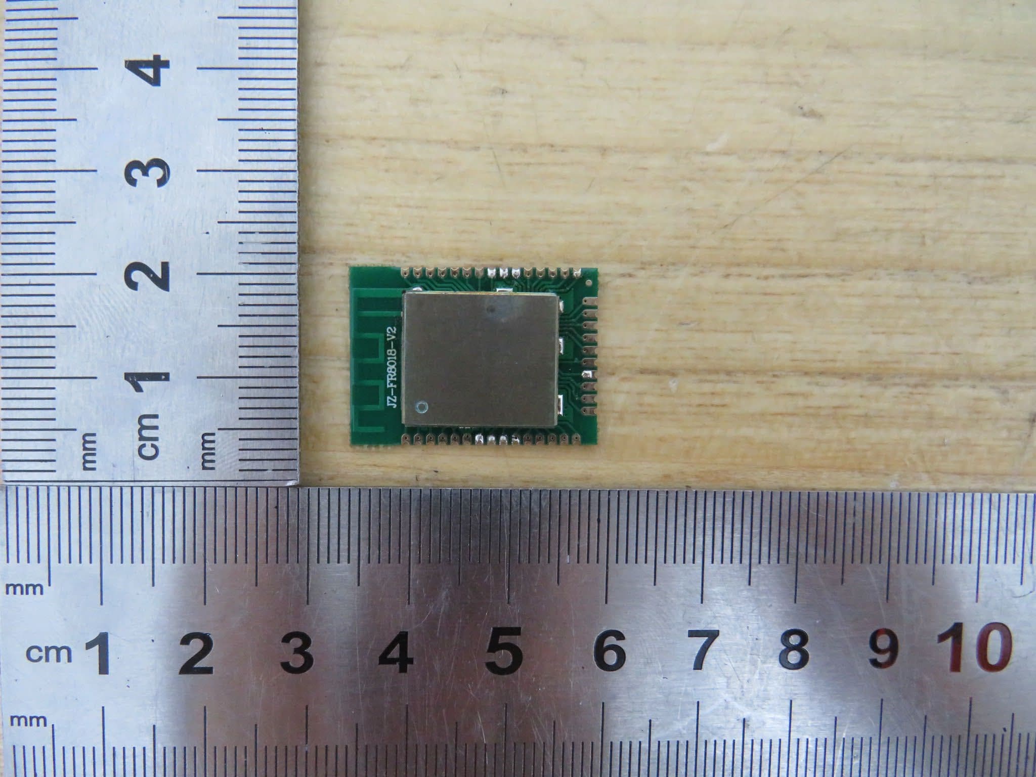
Click to zoom
Application Details
- Equipment Class
- DTS - Digital Transmission System
- Date of Grant
- Aug 24, 2023
- Application Purpose
- Original Equipment
- Date of Application
- Aug 24, 2023
- Equipment Note
- Bluetooth module
- Frequency Range
- 2402.00000000 - 2480.00000000
- Country
- China
Documents & Files
Document Text
Text extracted from the exhibit documents filed with the FCC. Open a document above to read the original.
Users Manual
1 Product Introduction 1.1 overview ZKBM01 is a highly integrated BLE Bluetooth transparent module with features such as small size, low power consumption, and ease of use, helping users develop Bluetooth applications at the lowest cost and fastest speed. After the module is started, it will automatically broadcast, and mobile devices can scan and connect it. After successful connection, users can communicate in both directions between the module and the mobile device. 1.2 Application scope Smart Home Related Products General LED lighting control for smart home related products, intelligent lighting such as Tmall Genie Logistics tracking, warehouse inspection, electronic labels, etc Wireless data acquisition and control of industrial instruments and meters Wireless remote control and voice remote control for electronic consumer products Wireless alarm and security system 1.3 pinouts Serial Number name types of describe 1 BLAS --- Retention function 2 MIC --- Retention function 3 A_P voice speaker+ 4 A_N voice speaker- 5 RST --- Reset foot 6 GND GND Power- 7 VCC VCC Power+ 8 VDDIO --- --- 9 ALL --- --- 10 ALO --- --- 11 PD7 I/O Retention function 12 PD6 I/O Retention function 13 PD5 I/O Retention function 14 PD4 I/O Retention function 15 DIO I/O Burn-SDA 16 TCK I/O Burn-SCL 17 PC5 I/O Retention function 18 PC3 I/O Retention function 19 PC2 I/O Retention function 20 PC1 I/O Retention function 21 PC0 I/O Retention function 22 PD3 I/O Retention function 23 PD2 I/O Retention function 24 PD1 I/O Retention function 25 PD0 I/O Retention function 26 PB4 I/O Retention function 27 PB6 I/O Retention function 28 PB7 I/O Retention function 29 PB5 I/O Retention function 30 PB1 I/O Retention function 31 PB2 I/O Retention function 32 PB3 I/O Retention function 33 PA3/TX I/O Serial 34 PA2/RX I/O Serial 35 PA1 I/O Retention function 36 PA0 I/O Retention function 37 PA7 I/O Retention function 38 PA6 I/O Retention function 39 PA4 I/O Retention function 40 PA5 I/O Retention function 2 hardware design 2.1 power The power supply voltage range of the module is between 1.8 and 4.3V, and cannot be outside this range. Exceeding this range may permanently damage the module. According to the application needs, the module can be powered separately or shared with the host device, but please choose a better power supply for the ripple system. If using a switching power supply, please pay attention to the interference of switching pulses on the module. Note: Normal working voltage of the module is DC 3.3V 2.2 IO power The module IO port has a TTL level of 3.3V. When connecting to the main control MCU, attention should be paid to level matching. The maximum input voltage that the module IO port can accept is 3.6V, which may damage the module. If the external MCU level is 5V, a transistor voltage conversion circuit or specialized voltage conversion chip can be used to convert it to a matching level and then connect it to the module IO port. For IO ports that are not used by the module, please hover or use a 10K resistor to pull them down to GND. 3 use 3.1 UART 1. The module can be used to upgrade firmware using a PC burning tool and a serial port. The specific operations are as follows: 2. Open the PC serial port burning tool, select the correct serial port number, import the DAT file (select the updated bin file), and then open the serial port to enter the waiting connection state. 3. Connect the TX of the serial tool to the chip PA2 (RXD1 on the module side) and RX to the chip PA3 (TXD1 on the module side). Attention: Because the TX of the serial port tool will be connected to the module end in series, the wiring connection sequence should follow the process described in steps 2 and 3 above, otherwise the module will not be successfully connected. 4 Contact Us Zhongshan Zhikong Intelligent Technology Co., Ltd 地址:Part II, 3rd Building, No.8 Building, No.3 Jiuzhou Avenue, Huoju Development Zone, Zhongshan City FCC Statement This equipment has been tested and found to comply with the limits for a Class B digital device, pursuant to part 15 of the FCC rules. These limits are designed to provide reasonable protection against harmful interference in a residential installation. This equipment generates, uses and can radiate radio frequency energy and, if not installed and used in accordance with the instructions, may cause harmful interference to radio communications. However, there is no guarantee that interference will not occur in a particular installation. If this equipment does cause harmful interference to radio or television reception, which can be determined by turning the equipment off and on, the user is encouraged to try to correct the interference by one or more of the following measures: -Reorient or relocate the receiving antenna. -Increase the separation between the equipment and receiver. -Connect the equipment into an outlet on a circuit different from that to which the receiver is connected. -Consult the dealer or an experienced radio/TV technician for help. This equipment complies with Part 15 of the FCC Rules. Operation is subject to the following two conditions: (1) This device may not cause harmful interference, and (2) This device must accept any interference received, including interference that may cause undesired operation. Any changes or modifications not expressly approved by the party responsible for compliance could void the user’s authority to operate the equipment. 2.2 This module has been assessed against the following FCC rule parts: CFR 47 FCC Part 15 C (15.247, DTS). It is applicable to the modular transmitter 2.3 This radio transmitter 2BBCH-ZKBM01 has been approved by Federal Communications Commission to operate with the antenna types listed below, with the maximum permissible gain indicated. Antenna types not included in this list that have a gain greater than the maximum gain indicated for any type listed are strictly prohibited for use with this device. The concrete contents to check are…
Text truncated - open the document above for the full version.
Attestation Statements
Date: 5/25/2023 Federal Communications Commissions Authorization and Evaluation Division 7435 Oakland Mills Road Columbia, MD 21046 RE: CFR 47 §2.911 (d)(7) FCC US Agent Letter of Attestation FCC ID : 2BBCH-ZKBM01 Grantee FRN: 0033661992 To whom it may concern: FCC US Agent Agent Company Name LoCo-Crazy Good Cookers, INC. Agent Contact Name Joseph Turner Agent US Address 506 Manchester Expressway Suite A2 Columbus GA 31904 USA Agent Email Address [email protected] Note: Agent LoCo-Crazy Good Cookers, INC. does not do any other business with the FCC This letter is to confirm that we have accepted the responsibility to act as US Agent on behalf of Zhongshan Zhikong Intelligent Technology Co., LTD (“the applicant”) for the above referenced FCC ID. We are aware of the requirements and responsibilities of the applicant’s agent for service of process as outlined in the FCC section 2.911(d)(7) and Report and Order FCC 22-84 paragraph 63. Sincerely, Authorized Agent Contact Person Name Joseph Turner Agent contact Job Title Engineer Agent Company name LoCo-Crazy Good Cookers, INC.
Attestation Statements
Date: 5/29/2023 Federal Communications Commissions Authorization and Evaluation Division 7435 Oakland Mills Road Columbia, MD 21046 RE: CFR 47 §2.911 (d)(7) Agent Designation Attestation FCC ID: 2BBCH-ZKBM01 Grantee FRN: 0033661992 Zhongshan Zhikong Intelligent Technology Co., LTD ("the applicant") as required by section 2.911(d)(7), designates the following agent, located in the United States, for purposes of acting as the applicant's agent for service of process. The applicant acknowledges that they will maintain an agent for no less than one year after the grantee has terminated all marketing and importation or the conclusion of any Commission-related proceeding involving the equipment. The applicant further acknowledges their responsibility under CFR 47 §2.929(c) to inform the FCC whenever the agent information changes. U.S. Agent lnfonnation: Agent Company Name: Loco-Crazy Good Cookers, INC. Agent Contact Name : Joseph Turner Agent US Address: 506 Manchester Expressway Suite A2 Columbus GA 31904 USA Agent Email Address [email protected] Note: Agent LoCo-Crazy Good Cookers, INC. does not do any other business with the FCC Sincerely yours, Name: Wentao Zhu Job Title: Certification Engineer Company Name: Zhongshan Zhikong Intelligent Technology Co., LTD
Cover Letter(s)
Modular Approval Request FCC (Per 15.212) FCC ID: 2BBCH-ZKBM01 Items to be covered Answer From Applicant 1. The radio elements of the modular transmitter must have their own shielding. The physical crystal and tuning capacitors may be located external to the shielded radio elements. Yes 2. The modular transmitter must have buffered modulation/data inputs (if such inputs are provided) to ensure that the module will comply with part 15 requirements under conditions of excessive data rates or over-modulation. Yes 3. The modular transmitter must have its own power supply regulation. Yes 4. The modular transmitter must comply with the antenna and transmission system requirements of §§ 15.203, 15.204(b) and 15.204(c). The antenna must either be permanently attached or employ a “unique” antenna coupler (at all connections between the module and the antenna, including the cable). The “professional installation” provision of § 15.203 is not applicable to modules but can apply to limited modular approvals under paragraph (b) of this section. Yes 5. The modular transmitter must be tested in a stand-alone configuration, i.e., the module must not be inside another device during testing for compliance with part 15 requirements. Unless the transmitter module will be battery powered, it must comply with the AC line conducted requirements found in § 15.207. AC or DC power lines and data input/output lines connected to the module must not contain ferrites, unless they will be marketed with the module (see § 15.27(a)). The length of these lines shall be the length typical of actual use or, if that length is unknown, at least 10 centimeters to insure that there is no coupling between the case of the module and supporting equipment. Any accessories, peripherals, or support equipment connected to the module during testing shall be unmodified and commercially available (see § 15.31(i)). Yes 6. The modular transmitter must be equipped with either a permanently affixed label or must be capable of electronically displaying its FCC identification number. (A) If using a permanently affixed label, the modular transmitter must be labeled with its own FCC identification number, and, if the FCC identification number is not visible when the module is installed inside another device, then the outside of the device into which the module is installed must also display a label referring to the enclosed module. This exterior label can use wording such as the following: “Contains Transmitter Module FCC ID: XYZMODEL1” or “Contains FCC ID: XYZMODEL1.” Any similar wording that expresses the same meaning may be used. The Grantee may either provide such a label, an example of which must be included in the application for equipment authorization, or, must provide adequate instructions along with the Yes module which explain this requirement. In the latter case, a copy of these instructions must be included in the application for equipment authorization. (B) If the modular transmitter uses an electronic display of the FCC identification number, the information must be readily accessible and visible on the modular transmitter or on the device in which it is installed. If the module is installed inside another device, then the outside of the device into which the module is installed must display a label referring to the enclosed module. This exterior label can use wording such as the following: “Contains FCC certified transmitter module(s).” Any similar wording that expresses the same meaning may be used. The user manual must include instructions on how to access the electronic display. A copy of these instructions must be included in the application for equipment authorization. 7. The modular transmitter must comply with any specific rules or operating requirements that ordinarily apply to a complete transmitter and the manufacturer must provide adequate instructions along with the module to explain any such requirements. A copy of these instructions must be included in the application for equipment authorization. Yes 8. Radio frequency devices operating under the provisions of this part are subject to the radio frequency radiation exposure requirements specified in §§ 1.1307(b), 1.1310, 2.1091, and 2.1093 of this chapter, as appropriate. Applications for equipment authorization of modular transmitters under this section must contain a statement confirming compliance with these requirements. The modular transmitter must comply with any applicable RF exposure requirements in its final configuration. Technical information showing the basis for this statement must be submitted to the Commission upon request. Yes Note: If compliance with one or more of the numbered requirements, listed above, cannot be demonstrated, it may be possible to obtain a “Limited Modular Approval” (LMA). Contact Name: Wentao Zhu Title of Person: Certification Engineer Company Name: Zhongshan Zhikong Intelligent Technology Co., LTD
External Photos
External Photographs View of EUT-1 Page 2 of 3 UL Verification Services (Guangzhou) Co., Ltd, Song Shan Lake Branch This report shall n ot be reproduced except in full, without the written approval of UL Verification Services (Guangzhou) Co., Ltd, Song Shan Lake Branch. . View of EUT-2 Antenna Page 3 of 3 UL Verification Services (Guangzhou) Co., Ltd, Song Shan Lake Branch This report shall n ot be reproduced except in full, without the written approval of UL Verification Services (Guangzhou) Co., Ltd, Song Shan Lake Branch. . View of EUT-3 View of EUT-4
ID Label/Location Info
Note: This label will permanently carved on shielding cover of the device.
Internal Photos
Internal Photographs Internal View of EUT-1 Page 2 of 2 UL Verification Services (Guangzhou) Co., Ltd, Song Shan Lake Branch This report shall not be reproduced except in full, without the written approval of UL Verification Services (Guangzhou) Co., Ltd, Song Shan Lake Branch. .
RF Exposure Info
The results reported herein have been performed in accordance with the laboratory’s terms of accreditation. This report shall not be reproduced except in full without the written approval of the Laboratory. The results in this report apply to the test sample(s) mentioned above at the time of the testing period only and are not to be used to indicate applicability to other similar products. FCC RF EXPOSURE REPORT CERTIFICATION TEST REPORT For Bluetooth module MODEL NUMBER: ZKBM01 REPORT NUMBER: 4790770330.1-RF-2 ISSUE DATE: May 8, 2023 FCC ID: 2BBCH-ZKBM01 Prepared for Zhongshan Zhikong Intelligent Technology Co., LTD Jiuzhou Avenue, Huoju Development Zone Zhongshan City Guangdong Province 528437 China Prepared by UL Verification Services (Guangzhou) Co., Ltd, Song Shan Lake Branch Building 10, Innovation Technology Park, No. 1, Li Bin Road, Song Shan Lake Hi- Tech Development Zone Dongguan, 523808, People’s Republic of China Tel: +86 769 22038881 Fax: +86 769 33244054 Website: www.ul.com REPORT NO.: 4790770330.1-RF-2 Page 2 of 7 UL Verification Services (Guangzhou) Co., Ltd, Song Shan Lake Branch FORM No.: 10-SL-F0112 This report shall not be reproduced except in full, without the written approval of UL Verification Services (Guangzhou) Co., Ltd, Song Shan Lake Branch. Revision History Rev. Issue Date Revisions Revised By V0 May 8, 2023 Initial Issue REPORT NO.: 4790770330.1-RF-2 Page 3 of 7 UL Verification Services (Guangzhou) Co., Ltd, Song Shan Lake Branch FORM No.: 10-SL-F0112 This report shall not be reproduced except in full, without the written approval of UL Verification Services (Guangzhou) Co., Ltd, Song Shan Lake Branch. TABLE OF CONTENTS 1. ATTESTATION OF TEST RESULTS ..................................................................................4 2. TEST METHODOLOGY ......................................................................................................5 3. FACILITIES AND ACCREDITATION ..................................................................................5 4. REQUIREMENT ..................................................................................................................6 REPORT NO.: 4790770330.1-RF-2 Page 4 of 7 UL Verification Services (Guangzhou) Co., Ltd, Song Shan Lake Branch FORM No.: 10-SL-F0112 This report shall not be reproduced except in full, without the written approval of UL Verification Services (Guangzhou) Co., Ltd, Song Shan Lake Branch. 1. ATTESTATION OF TEST RESULTS Applicant Information Company Name: Zhongshan Zhikong Intelligent Technology Co., LTD Address: Jiuzhou Avenue, Huoju Development Zone Zhongshan City Guangdong Province 528437 China Manufacturer Information Company Name: Zhongshan Zhikong Intelligent Technology Co., LTD Address: Jiuzhou Avenue, Huoju Development Zone Zhongshan City Guangdong Province 528437 China EUT Information EUT Name: Bluetooth module Model: ZKBM01 Sample Received Date: March 20, 2023 Sample Status: Normal Sample ID: 5900920 Date of Tested: April 19, 2023 to May 8, 2023 APPLICABLE STANDARDS STANDARD TEST RESULTS FCC 47CFR§2.1091 PASS Prepared By: Checked By: Fanny Huang Denny Huang Engineer Project Associate Senior Project Engineer Approved By: Stephen Guo Operations Manager REPORT NO.: 4790770330.1-RF-2 Page 5 of 7 UL Verification Services (Guangzhou) Co., Ltd, Song Shan Lake Branch FORM No.: 10-SL-F0112 This report shall not be reproduced except in full, without the written approval of UL Verification Services (Guangzhou) Co., Ltd, Song Shan Lake Branch. 2. TEST METHODOLOGY The tests documented in this report were performed in accordance with 47 CFR FCC Part 2 Subpart J, section 2.1091 and KDB447498D01v06. 3. FACILITIES AND ACCREDITATION Accreditation Certi ficate A2LA (Certificate No.: 4102.01) UL Verification Services (Guangzhou) Co., Ltd. Song Shan Lake Branch. has been assessed and proved to be in compliance with A2LA. FCC (FCC Designation No.: CN1187) UL Verification Services (Guangzhou) Co., Ltd. Song Shan L ake Branch. Has been recognized to perform compliance testing on equipment subject to the Commission's Delcaration of Conformity (DoC) and Certification rules ISED (Company No.: 21320) UL Verification Services (Guangzhou) Co., Ltd. Song Shan Lake Branch. has been r egistered and fully described in a report filed with ISED. The Company Number is 21320 and the test lab Conformity Assessment Body Identifier (CABID) is CN0046. VCCI (Registration No.: G-20019, R-20004, C-20012 and T-20011) UL Veri fi cation Services (Guangzhou) Co., Ltd. Song Shan Lake Branch. has been assessed and proved to be in compliance w ith VCCI, the Membership No. is 3793. Facility Name: Chamber D, the VCCI registration No. is G-20019 and R-20004 Shielding Room B , the VCCI registration No. is C-20012 and T-20011 Note: All tests measurement facilities use to collect the measurement data are located at Building 1 0, Innovation Technology Park, Song Shan Lake Hi tech Development Zone, Dongguan, 523808, China. REPORT NO.: 4790770330.1-RF-2 Page 6 of 7 UL Verification Services (Guangzhou) Co., Ltd, Song Shan Lake Branch FORM No.: 10-SL-F0112 This report shall not be reproduced except in full, without the written approval of UL Verification Services (Guangzhou) Co., Ltd, Song Shan Lake Branch. 4. REQUIREMENT LIMIT AND CALCULATION METHOD Systems operating under the provisions of FCC 47 CFR section shall be operated in a manner that ensures that the public is not exposed to radio frequency energy level in excess of the Commission’s guidelines. I n accordance with 47 CFR FCC Part 2 Subpart J, section 2.1091 this device has been defined as mobile device whereby a distance of 0.2m normally can be maintained between the user and the device, and below RF Permissible Exposure limit shall comply with. Limits for General P opulation/Uncontrolled Exposure RF EXPOSURE LIMIT Frequency Range (MHz) E-field Strength (E) (V/m) Magnetic Field Strength (H) (A/m) Power Density (S) (mW/cm 2 ) Averaging Time |E| 2 , |H| 2 or S (M…
Text truncated - open the document above for the full version.
Test Report
The results reported herein have been performed in accordance with the laboratory’s terms of accreditation. This report shall not be reproduced except in full without the written approval of the Laboratory. The results in this report apply to the test sample(s) mentioned above at the time of the testing period only and are not to be used to indicate applicability to other similar products. CFR 47 FCC PART 15 SUBPART C ISED RSS-247 ISSUE 2 TEST REPORT For Bluetooth module MODEL NUMBER: ZKBM01 REPORT NUMBER: 4790770330.1-RF-1 ISSUE DATE: May 8, 2023 FCC ID: 2BBCH-ZKBM01 IC: 30341-ZKBM01 Prepared for Zhongshan Zhikong Intelligent Technology Co., LTD Jiuzhou Avenue, Huoju Development Zone Zhongshan City Guangdong Province 528437 China Prepared by UL Verification Services (Guangzhou) Co., Ltd, Song Shan Lake Branch Building 10, Innovation Technology Park, No. 1, Li Bin Road, Song Shan Lake Hi- Tech Development Zone Dongguan, 523808, People’s Republic of China Tel: +86 769 22038881 Fax: +86 769 33244054 Website: www.ul.com REPORT NO.: 4790770330.1-RF-1 Page 2 of 73 UL Verification Services (Guangzhou) Co., Ltd, Song Shan Lake Branch FORM NO: 10-SL-F0035 This report shall not be reproduced except in full, without the written approval of UL Verification Services (Guangzhou) Co., Ltd, Song Shan Lake Branch. Revision History Rev. Issue Date Revisions Revised By V0 May 8, 2023 Initial Issue REPORT NO.: 4790770330.1-RF-1 Page 3 of 73 UL Verification Services (Guangzhou) Co., Ltd, Song Shan Lake Branch FORM NO: 10-SL-F0035 This report shall not be reproduced except in full, without the written approval of UL Verification Services (Guangzhou) Co., Ltd, Song Shan Lake Branch. Summary of Test Results Test Item Clause Limit/Requirement Result Antenna Requirement N/A FCC Part 15.203/15.247 (c) RSS-GEN Clause 6.8 Pass AC Power Line Conducted Emission ANSI C63.10-2013, Clause 6.2 FCC Part 15.207 RSS-GEN Clause 8.8 Pass Conducted Output Power ANSI C63.10-2013, Clause 11.9.1.3 FCC Part 15.247 (b)(3) RSS-247 Clause 5.4 (d) Pass 6dB Bandwidth and 99% Occupied Bandwidth ANSI C63.10-2013, Clause 11.8.1 FCC Part 15.247 (a)(2) RSS-247 Clause 5.2 (a) ISED RSS-Gen Clause 6.7 Pass Power Spectral Density ANSI C63.10-2013, Clause 11.10.2 FCC Part 15.247 (e) RSS-247 Clause 5.2 (b) Pass Conducted Band edge and spurious emission ANSI C63.10-2013, Clause 11.11 FCC Part 15.247(d) RSS-247 Clause 5.5 Pass Radiated Band edge and Spurious Emission ANSI C63.10-2013, Clause 11.12 & Clause 11.13 FCC Part 15.247 (d) FCC Part 15.205/15.209 RSS-247 Clause 5.5 RSS-GEN Clause 8.9 Pass Duty Cycle ANSI C63.10-2013, Clause 11.6 None; for reporting purposes only. Pass *This test report is only published to and used by the applicant, and it is not for evidence purpose in China. *The measurement result for the sample received is <Pass> according to <CFR 47 FCC PART 15 SUBPART C><ISED RSS-247 ISSUE 2> when <Accuracy Method> decision rule is applied. REPORT NO.: 4790770330.1-RF-1 Page 4 of 73 UL Verification Services (Guangzhou) Co., Ltd, Song Shan Lake Branch FORM NO: 10-SL-F0035 This report shall not be reproduced except in full, without the written approval of UL Verification Services (Guangzhou) Co., Ltd, Song Shan Lake Branch. CONTENTS 1. ATTESTATION OF TEST RESULTS ...................................................................................... 6 2. TEST METHODOLOGY .......................................................................................................... 7 3. FACILITIES AND ACCREDITATION ...................................................................................... 7 4. CALIBRATION AND UNCERTAINTY ..................................................................................... 8 4.1. MEASURING INSTRUMENT CALIBRATION ............................................................ 8 4.2. MEASUREMENT UNCERTAINTY ............................................................................. 8 5. EQUIPMENT UNDER TEST .................................................................................................... 9 5.1. DESCRIPTION OF EUT ............................................................................................. 9 5.2. CHANNEL LIST .......................................................................................................... 9 5.3. MAXIMUM EIRP ......................................................................................................... 9 5.4. TEST CHANNEL CONFIGURATION ......................................................................... 9 5.5. THE WORSE CASE POWER SETTING PARAMETER .......................................... 10 5.6. DESCRIPTION OF AVAILABLE ANTENNAS .......................................................... 10 5.7. SUPPORT UNITS FOR SYSTEM TEST .................................................................. 11 6. MEASURING EQUIPMENT AND SOFTWARE USED ......................................................... 12 7. ANTENNA PORT TEST RESULTS ...................................................................................... 15 7.1. CONDUCTED OUTPUT POWER ............................................................................ 15 7.2. 6DB BANDWIDTH AND 99% OCCUPIED BANDWIDTH ........................................ 16 7.3. POWER SPECTRAL DENSITY ............................................................................... 18 7.4. CONDUCTED BAND EDGE AND SPURIOUS EMISSION...................................... 20 7.5. DUTY CYCLE ........................................................................................................... 22 8. RADIATED TEST RESULTS ................................................................................................ 23 8.1. RESTRICTED BANDEDGE ..................................................................................... 31 8.2. SPURIOUS EMISSIONS(1 GHZ~3 GHZ) ................................................................ 35 8.3. SPURIOUS EMISSIONS(3 GHZ~18 GHZ) ...........................…
Text truncated - open the document above for the full version.
Test Report
UL Verification Services (Guangzhou) Co., Ltd, Song Shan Lake Branch This report shall not be reproduced except in full, without the written approval of UL Verification Services (Guangzhou) Co., Ltd, Song Shan Lake Branch. Antenna Gain Test Report Project No.: 4790770330 Client Name: Zhongshan Zhikong Intelligent Technology Co., LTD Client Address: Room 1206, Block 2, No.10, Shengping Middle Road, Xiaolan Town, Zhongshan City Product Name: Product Model: Bluetooth module ZKBM01 Manufacture: / Antenna Type: PCB Antenna Size: / Test Standards: ANSI/IEEE std 149-2021 Test Date: 2023.4.26 Issued Date: 2023.4.26 Prepared By: Burt Hu Laboratory Engineer Reviewed By: James Q in Project Engineer Approved By: Stephen Guo Laboratory Manager UL Verification Services (Guangzhou) Co., Ltd, Song Shan Lake Branch This report shall not be reproduced except in full, without the written approval of UL Verification Services (Guangzhou) Co., Ltd, Song Shan Lake Branch. 1 Test Equipment Information Equipment Manufacturer Mode No. Serial No. Cal date Cal Due Test Chamber ETS-Lindgren 8500 / / / Test Software ETS-Lindgren EMQuest V1.12 1496 / / Network Analyzer Keysight E5071C MY46524531 2022.10.17 2023.10.16 EXA Singal Analyzer Keysight N9010A MY55150514 2022.10.17 2023.10.16 2 Setup block diagram UL Verification Services (Guangzhou) Co., Ltd, Song Shan Lake Branch This report shall not be reproduced except in full, without the written approval of UL Verification Services (Guangzhou) Co., Ltd, Song Shan Lake Branch. 3 Test Temperature and Humidity Temperature: 22.6°C Humidity: 62.3% 4 Test Step Flow 1) Maintain the test ambient temperature of 23±2 °C, the instrument is powered on and preheated for more than 30 minutes; 2) Turn on the darkroom power supply, connect the test cable, and set up the sample according to the standard; 3) Outline sets the test content objectives and conducts calibration tests; 4) Run the software, when the test is completed, export the corresponding test diagram and test data, and save to the corresponding directory. 5 Test Result 2.4GHz Frequency (MHz) Efficiency (%) Gain (dBi) 2400 44.54 0.09 2410 46.39 -0.11 2420 48.55 -0.30 2430 50.01 -0.53 2440 50.94 -0.81 2450 51.05 -1.11 2460 50.82 -1.41 2470 50.17 -1.72 2480 49.76 -2.10 2490 49.90 -2.32 2500 49.79 -2.53 MAX 51.05 0.09 UL Verification Services (Guangzhou) Co., Ltd, Song Shan Lake Branch This report shall not be reproduced except in full, without the written approval of UL Verification Services (Guangzhou) Co., Ltd, Song Shan Lake Branch. Polarization Pattern Photos 2.4GHz Theta Polarization(Theta Angle=90°) Phi Polarization(Theta Angle=90°) UL Verification Services (Guangzhou) Co., Ltd, Song Shan Lake Branch This report shall not be reproduced except in full, without the written approval of UL Verification Services (Guangzhou) Co., Ltd, Song Shan Lake Branch. Total 3D Plot(Fre.2500MHz) UL Verification Services (Guangzhou) Co., Ltd, Song Shan Lake Branch This report shall not be reproduced except in full, without the written approval of UL Verification Services (Guangzhou) Co., Ltd, Song Shan Lake Branch. UL Verification Services (Guangzhou) Co., Ltd, Song Shan Lake Branch This report shall not be reproduced except in full, without the written approval of UL Verification Services (Guangzhou) Co., Ltd, Song Shan Lake Branch. 6 Photo END OF REPORT
Test Setup Photos
Appendix II Setup Photographs RADIATED RF MEASUREMENT SETUP (ABOVE 1 GHz) MEASUREMENT POSITION MEASUREMENT POSITION (X axis) MEASUREMENT POSITION (Y axis) MEASUREMENT POSITION (Z axis) RADIATED RF MEASUREMENT SETUP (30MHz~1GHz) RADIATED RF MEASUREMENT SETUP (Below 30MHz) POWERLINE CONDUCTED EMISSIONS MEASUREMENT SETUP
Contact Information
Applicant
Wentao Zhu
Test Firm
UL Verification Services (Guangzhou) Co., Ltd.Stephen Guo
[email protected]+86 0769 33817120
Technical Specifications
| # | Rule Parts | Frequency Range | Power Output |
|---|---|---|---|
| 1 | 15C | 2.40 GHz - 2.48 GHz | 1.00 mW |