2BBF7-2448BTDIGITAL AUDIO PROCESSOR
STETSOM ELECTRONICS USA INC.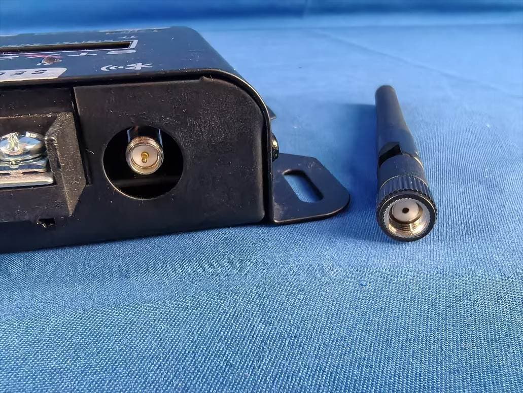
Click to zoom
Application Details
- Equipment Class
- DTS - Digital Transmission System
- Date of Grant
- Jun 24, 2026
- Application Purpose
- Original Equipment
- Equipment Note
- DIGITAL AUDIO PROCESSOR
- Frequency Range
- 2402.00000000 - 2480.00000000
- Company
- STETSOM ELECTRONICS USA INC.
- Country
- United States
Documents & Files
Document Text
Text extracted from the exhibit documents filed with the FCC. Open a document above to read the original.
Users Manual
MANUAL DO USUÁRIO USER MANUAL • MANUAL DE USUARIO Controlado por DIGITAL AUDIo PROCESSORDIGITAL AUDIo PROCESSOR Clique para download ou acesse o QRCODE. Click to download or access the QRCODE. 2 ENGLISH Features O The processor includes 2 input channels (A and B) and 4 independent output channels (1, 2, 3, and 4), as follows: MAIN IN: Connection RCA (A e B) OUT 1: RCA (L + R) HIGH-IN: Connection FIO (A e B) OUT 2: RCA (L + R) INPUTS OUT 3: RCA (L + R) OUT 4: RCA (L + R) RCA INPUT (LINE) Common in aftermarket head units and audio equipment. HIGH CONNECTION (WIRE) Common in factory head units and original vehicle audio systems. INPUT CONNECTIONS OUTPUTS Introduction Thank you for choosing STETSOM! The STX2448BT was designed to enhance your audio experience by modernizing the well-known STX2448. Now featuring Bluetooth technology and a dedicated app for Android and iOS, it offers full control of the processor directly from your smartphone — no need for physical access to the device. The new DSP brings advanced professional features, allowing precise, customized fine- tuning, making it ideal for any sound system project, whether automotive or home audio. It also includes three dedicated outputs for the sequencer feature, which enables multiple devices to be powered on or off in sequence. This function can be configured either on the processor itself or via the app. 3 The digital signal processing features allow precise audio adjustments through a variety of integrated functions and tools: • AUDIO ADJUSTMENTS DIRECTLY ON THE PROCESSOR OR THROUGH THE MOBILE APP; • RCA & HIGH-LEVEL (WIRE) AUDIO INPUTS; • GRAPHIC EQUALIZER; • PARAMETRIC EQUALIZERS for both input and output; • Flexible input-to-output ROUTING; • High-precision CROSSOVER (with Butterworth, Linkwitz-Riley, and Bessel filters); • High-precision DELAY; • PHASE INVERSION; • LIMITER with adjustable Threshold, Attack, and Release; • MASTER VOLUME, GAIN, and MUTE control for each output; • CHANNEL LINK for simultaneous parameter adjustments across linked channels; • AUTOMATIC SAVE and LOAD for storing and retrieving audio settings; • SECURITY PASSWORD to prevent unauthorized parameter changes; • FREQUENCY GENERATOR and sweep function; • Integrated SEQUENCER for remote triggering with configurable timing. 4 Before installation Please read this manual carefully before using the product. • All product connections must be made with the unit turned OFF. • Installing a fuse between the product and the battery is mandatory for protection against overload. The fuse must match the product's current draw and be installed as close to the battery as possible. • Use the wire gauges recommended in this manual to prevent cable overheating and ensure maximum performance. • Keep the cables as short as possible to increase sound fidelity and avoid potential power loss. • Route the installation cables as far as possible from the vehicle’s original wiring to minimize interference and noise in your audio system. • Connect the Bluetooth antenna to the designated connector on the processor, making sure it is firmly attached for optimal signal reception. • For best performance, install the processor in a location with minimal metal obstructions to avoid signal dampening inside the vehicle. • Install in a secure, well-ventilated, and dry area. • Installation should be performed by a qualified professional. If you have any questions, please contact the store where the installation was performed or reach out to our Customer Support Center (SAC) at: +55 18 2104 9412. 5 INPUT: The processor features two types of input connections: RCA and HIGH (WIRE Input). Both share the same input channels (A and B), so you can use them according to your needs.. OUTPUT: Features 4 independent RCA outputs (L+R) for connecting amplifiers and other audio equipment. These outputs are processed according to the audio parameters set by the user. Processor overview 1 2 IN B IN A IN BIN A The negative wire is represented by the GRAY wire. The positive wire is represented by the BLUE wire. CONEXÃO MAIN (RCA) 21 Using both RCA and HIGH INPUT connections at the same time may cause unwanted noise. HIGH IN CONNECTION (WIRE) 6 5 SEQUENCED POWER-ON SYSTEM (SEQUENCER): The processor features three dedicated outputs for the sequencer function, allowing multiple devices to be powered on or off in sequence. These connections can be configured directly on the processor or via the mobile app. Use cables with a minimum gauge of 18 AWG to ensure a safe and efficient connection. INPUT CLIP INDICATOR: Indicates that the incoming audio level is too high, which may cause distortion. Adjust the source volume to prevent damage and ensure better sound quality. LCD DISPLAY: Allows for viewing and interacting with the processor’s system. 3 4 5 HOTKEY BUTTONS: Dedicated buttons for selecting the channel to apply parameters or for activating the MUTE function. 6 PRESS AND HOLD: Hold to ENABLE or DISABLE the channel's MUTE mode. PRESS AND RELEASE: Press to quickly select the channel where audio parameters will be applied. BLUE LED Indicates the output channel is active. RED LED Indicates the output channel is muted (OFF). 467 389 10 7 REMOTE TURN-ON CONNECTOR (REM): Activates the processor when this connection is powered. Connect the remote output from the head unit/player using an 18 AWG wire, or use a manual on/off switch connected to a 12V power source. POSITIVE CONNECTOR : Connect to the positive terminal of the battery or a 12V power supply using a cable with a minimum gauge of 13 AWG. If using the vehicle’s battery, install a 1A fuse for electrical protection no more than 12 inches from the battery. NEGATIVE/GROUND CONNECTOR : Connect to the negative terminal of the battery or power supply using a 13 AWG wire. USING THE PROCESSOR DIRECTLY WITH A 12V POWER SUPPLY. ON/OFF SWITCH Used for MANUAL activation when the REM connection is not linked to the head unit’s remote output. POWER SUPPLY OPERATING MODES: PRESS…
Text truncated - open the document above for the full version.
Attestation Statements
Rev 1/26/2023 STETSOM ELECTRONICS USA INC. Federal Communications Commission Authorization and Evaluation Division 7435 Oakland Mills Road Columbia, MD 21046 USA Date: 03‐29‐2026 Ref: Attestation Statements Part 2.911(d)(7) Filing FCC ID: 2BBF7-2448BT STETSOM ELECTRONICS USA INC. (“the applicant”) certifies that, as of the date of the filing of the application, we designate ourselves as the U.S. agent for service of process. Designated U.S. Agent Information: FRN: 0033839143 Name: STETSOM ELECTRONICS USA INC. Address: 66 WEST FLAGLER ST STE 900/7434, MIAMI, FLORIDA, USA Contact Person: Fernando Kanada Tel.: (786) 743‐0031 Email: [email protected] Sincerely, STETSOM ELECTRONICS USA INC. Fernando Kanada
Attestation Statements
STETSOM ELECTRONICS USA INC. Date: 03‐26‐2026 Eurofins Electrical and Electronic Testing NA, Inc. 914 West Patapsco Avenue Baltimore, MD 21230 RE: Attestation Statements Part 2.911(d)(5)(i) request for FCC ID: 2BBF7‐2448BT [STETSOM ELECTRONICS USA INC.] (“the applicant”) certifies that the equipment for which authorization is sought is not “covered” equipment prohibited from receiving an equipment authorization pursuant to section 2.903 of the FCC rules. We also certify that, as of the date of the filing of the application, the equipment does not utilize cyber‐security or anti‐virus software from Kaspersky Lab, Inc, or any of its successors and assignees, which is also on the “covered list”. Sincerely, Fernando Kanada STETSOM ELECTRONICS USA INC. Date: 03‐26‐2026 Eurofins Electrical and Electronic Testing NA, Inc. 914 West Patapsco Avenue Baltimore, MD 21230 RE: Attestation Statements Part 2.911(d)(5)(ii) request for FCC ID: 2BBF7‐2448BT [STETSOM ELECTRONICS USA INC.] (“the applicant”) certifies that, as of the date of the filing of the application, the applicant is not identified on the Covered List as an entity producing “covered” equipment. Sincerely, Fernando Kanada
Cover Letter(s)
STETSOM ELECTRONICS USA INC. Date: Mar 26, 2026 Federal Communications Commission Authorization and Evaluation Division Confidentiality Request regarding application for certification of FCC ID: 2BBF7-2448BT Pursuant to Sections 0.457 and 0.459 of the Commission’s Rules, we hereby request confidential treatment of information accompanying this application as outlined below: Exhibit Type File Name Long-term confidentiality: Schematics Block Diagram Operational Description Schematics.pdf Block Diagram.pdf Operational Description.pdf The above materials contain trade secrets and proprietary information not customarily released to the public. The public disclosure of these materials may be harmful to the applicant and provide unjustified benefits to its competitors. The applicant understands that pursuant to Section 0.457 of the Rules, disclosure of this application and all accompanying documentation will not be made before the date of the Grant for this application. Sincerely, STETSOM ELECTRONICS USA INC. Fernando Kanada / Project Coordinator Typed name and Title
Cover Letter(s)
STETSOM ELECTRONICS USA INC. FCC ID: 2BBF7-2448BT POWER OF ATTORNEY Date: Mar 26, 2026 Federal Communications Commission Authorization and Evaluation Division 7435 Oakland Mills Road Columbia, MD 21046 To Whom It May Concern: We, the undersigned, hereby authorize Waltek Testing Group Co., Ltd. (Deval Qin) on our behalf, to apply to the Federal Communications Commission on our equipment. Any and all acts carried out by Waltek Testing Group Co., Ltd. (Deval Qin) on our behalf shall have the same effect as acts of our own. This authorization expires on Mar 25, 2027. Sincerely, STETSOM ELECTRONICS USA INC. Fernando Kanada / Project Coordinator Typed name and Title
External Photos
Appendix- STX 2448BT -Photos Reference No.: WTD26D03060463WPage 3 of 9 2. Photographs –Constructional Details 2.1. EUT – External View Model STX 2448BT FCC ID: 2BBF7-2448BT 】 Appendix- STX 2448BT -Photos Reference No.: WTD26D03060463WPage 4 of 9 Appendix- STX 2448BT -Photos Reference No.: WTD26D03060463WPage 5 of 9 ANT Appendix- STX 2448BT -Photos Reference No.: WTD26D03060463WPage 6 of 9
ID Label/Location Info
Label: Label Location:
Internal Photos
Appendix- STX 2448BT -Photos Reference No.: WTD26D03060463WPage 7 of 9 2.2. EUT – Internal View Model STX 2448BT FCC ID: 2BBF7-2448BT Appendix- STX 2448BT -Photos Reference No.: WTD26D03060463WPage 8 of 9 Appendix- STX 2448BT -Photos Reference No.: WTD26D03060463WPage 9 of 9 ======End======
RF Exposure Info
Waltek Testing Group Co., Ltd. http://www.waltek.com.cn Page 1 of 8 TEST REPORT Reference No. .................... : WTD26D03060463W003 FCC ID ................................ : 2BBF7-2448BT Applicant ............................ : STETSOM ELECTRONICS USA INC. Address .............................. : 66 WEST FLAGLER ST STE 900/7434, MIAMI, FLORIDA, USA Manufacturer .................... : STETSOM ELECTRONICS USA INC. Address .............................. : 66 WEST FLAGLER ST STE 900/7434, MIAMI, FLORIDA, USA Product ............................... : DIGITAL AUDIO PROCESSOR Model(s). ............................ : STX 2448BT Standards........................... : FCC 47CFR Part 2 Subpart J Section 2.1091 Date of Receipt Sample .... : 2026-03-18 Date of Test........................ : 2026-04-04 to 2026-04-20 Date of Issue ...................... : 2026-06-12 Test Result ......................... : Pass Remarks: The results shown in this test report refer only to the sample(s) tested, this test report cannot be reproduced, except in full, without prior written permission of the company. The report would be invalid without specific stamp of test institute and the signatures of compiler and approver. Prepared By: Waltek Testing Group Co., Ltd. Address: No. 77, Houjie Section, Guantai Road, Houjie Town, Dongguan City, Guangdong, China Tel: +86-769-2267 6998 Fax: +86-769-2267 6828 Compiled by: Approved by: Estel Qian/ Project Engineer Deval Qin / Designated Reviewer Reference No.: WTD26D03060463W003 Page 2 of 8 Waltek Testing Group Co., Ltd. http://www.waltek.com.cn 2. Contents Page 1 COVER PAGE ........................................................................................................................................... 1 2. CONTENTS ............................................................................................................................................... 2 3. REVISION HISTORY................................................................................................................................. 3 4. GENERAL INFORMATION ....................................................................................................................... 4 4.1. GENERAL DESCRIPTION OF E.U.T. .................................................................................................. 4 4.2. DETAILS OF E.U.T. ......................................................................................................................... 4 4.3. TEST FACILITY ................................................................................................................................ 5 4.4. SUBCONTRACTED ........................................................................................................................... 5 4.5. ABNORMALITIES FROM STANDARD CONDITIONS ................................................................................ 5 5. TEST SUMMARY ...................................................................................................................................... 6 6. RF EXPOSURE ......................................................................................................................................... 7 6.1. REQUIREMENTS .............................................................................................................................. 7 6.2. THE PROCEDURES / LIMIT ................................................................................................................ 7 6.3. MPE CALCULATION METHOD........................................................................................................... 8 6.4. RADIO FREQUENCY RADIATION EXPOSURE EVALUATION ................................................................... 8 Reference No.: WTD26D03060463W003 Page 3 of 8 Waltek Testing Group Co., Ltd. http://www.waltek.com.cn 3. Revision History Test Report No. Date of Receipt Sample Date of Test Date of Issue Purpose Comment Approved WTD26D03060463W003 2026-03-18 2026-04-04 to 2026-04-20 2026-06-12 Original - Valid Reference No.: WTD26D03060463W003 Page 4 of 8 Waltek Testing Group Co., Ltd. http://www.waltek.com.cn 4. General Information 4.1. General Description of E.U.T. Product: DIGITAL AUDIO PROCESSOR Model(s): STX 2448BT Model Description: N/A Test Sample No.: 1-1/1 Bluetooth Version: Bluetooth 5.2 Low Energy Hardware Version: SCH_R1D – PCB_R1B Software Version: 2.4 4.2. Details of E.U.T. Operation Frequency: 2402~2480MHz Max. RF output power: 0.20dBm Modulation Technology: GFSK Antenna installation: External antenna with RP-SMA connector Antenna Gain: 2.74dBi Note: #: The antenna gain is provided by the applicant, and the applicant should be responsible for its authenticity, WALTEK lab has not verified the authenticity of its information. Ratings: 9.0V~16V DC Reference No.: WTD26D03060463W003 Page 5 of 8 Waltek Testing Group Co., Ltd. http://www.waltek.com.cn 4.3. Test Facility The test facility has a test site registered with the following organizations: ISED CAB identifier: CN0013. Test Firm Registration No.: 7760A. Waltek Testing Group Co., Ltd. Has been registered and fully described in a report filed with the Industry Canada. The acceptance letter from the Industry Canada is maintained in our files. Registration number 7760A, October 15, 2016. FCC Designation No.: CN1201. Test Firm Registration No.: 523476. Waltek Testing Group Co., Ltd. EMC Laboratory has been registered and fully described in a report filed with the (FCC) Federal Communications Commission. The acceptance letter from the FCC is maintained in our files. Registration number 523476, September 10, 2019. 4.4. Subcontracted Whether parts of tests for the product have been subcontracted to other labs: Yes No If Yes, list the related test items and lab information: Test Lab: N/A Lab address: N/A Test items: N/A 4.5. Abnormalities from Standard Conditions None. Reference No.: WTD26D03060463W003 Page 6 of 8 Waltek Testing Group Co., Ltd. http…
Text truncated - open the document above for the full version.
Test Report
上海增信电子有限公司 ShangHai Signal Plus Technology Co.,Ltd. 规 格 承 认 书 SPECIFICATION FOR APPROVAL 日期 DATE: 版本 REV.: 客 户 CUSTOMER: 客 户 料 号 CUSTOMER P/N: 品 名 PART NAME: 供 方 料 号 External antenna Black 2.4G 2.5dBi RP SMA-Male SUPPLIER P/N: 送样日期 Date: 送样数量 Q’TY:Pcs 客户确认 CUSTOMER APPROVED BY 核准 Approvaled by 审核 Checked by 拟制 Prepared by 供方确认 SUPPLIER SIGNATURE 核准 Approvaled by 审核 Checked by 拟制 Prepared by Jackandy ZX-QT-RD-0011-A1 Add: 上海市徐汇区桂箐路 69 号 30 栋 603 室 Tel:021-54266190 Fax:021-54266191 WZW02SMAJ002-3 List of contents Test setup Antenna Solution S Parameter---Return Loss、Isolation Efficiency and Peak Gain Radiation Patterns Signal Plus Antennas 1.Test system description---S Parameter 1.1.Test Setup 1.1.1 VNA Test Setup S parameter measurements (S 11 ) were performed using an KeySight E5071C Network Analyzer and previously described tests fixtures. The isolation between antennas is also tested. The testing was performed with apparatus in free space. Signal Plus Antennas 1.1.2 Anechoic Chamber Test Setup The gain of the antenna was measured in the anechoic chamber(ETS-3D). The chamber provides less than –30 dB reflectivity from 400 MHz through 6 GHz. The chamber size is:7m*4m*3m.The measurement results are calibrated using a leaky wave horn standard. We can measure the antenna gain and efficiency accurately. +Z +Y +X Horn Antenna Signal Plus Antennas 1.Test system description--- Anechoic Chamber Test Setup 1.1.3 Instruments R&S CMW500 4G/WIFI (LTE/WIFI b/g/a) Agilent 8960 2G/3G (GSM/CDMA/WCDMA) KeySight E5071C (400MHz~6GHz) Signal Plus Antennas 1.Test system description--- Test Instruments 2. Antenna Solution 2.1 Antenna Location Pictures Signal Plus Antennas X X Z Y 2.Antenna Solution 2.1 Antenna Location Pictures Signal Plus Antennas Data: Signal Plus Antennas Freq.(MHz) 2400 2450 2500 VSWR 1.52 1.28 1.35 Gain(dBi) 2.34 2.74 2.23 Eff.(%) 72.30 86.10 75.50 3.Test Result---Efficiency、Gain 2.4G-Ant 1 3.Test Result---Return Loss S11(2.4G-ANT1): Signal Plus Antennas Signal Plus Antennas 3.Test Result---Radiation Patterns Data: 2.4G-Ant 1
Test Report
Waltek Testing Group Co., Ltd. http://www.waltek.com.cn Pa ge 1 of 28 TEST REPORT Referen ce No. .................... : WTD26D03060463W002 FCC ID ................................ : 2BBF7-2448BT Applicant ............................ : STETSOM ELECTRONICS USA INC. Address .............................. : 66 WEST FLAGLER ST STE 900/7434, MIAMI, FLORIDA, USA Manufacturer .................... : STETSOM ELECTRONICS USA INC. Address .............................. : 66 WEST FLAGLER ST STE 900/7434, MIAMI, FLORIDA, USA Product ............................... : DIGITAL AUDIO PROCESSOR Model(s). ............................ : STX 2448BT Standards........................... : FCC 47CFR Part 15.247 Date of Receipt Sample .... : 2026-03-18 Date of Test ....................... : 2026-04-04 to 2026-04-20 Date of Issue ...................... : 2026-06-12 Test Result ......................... : Pass Remarks: The res ults shown in this test report refer only to the sample(s) tested, this test report cannot be reproduced, except in full, without prior written permission of the company. The report would be invalid without specific stamp of test institute and the signatures of compiler and approver. Prepared By: Waltek Testing Group Co., Ltd. Address: No. 77, Houjie Section, Guantai Road, Houjie Town, Dongguan City, Guangdong, China Tel: +86-769-2267 6998 Fax: +86-769-2267 6828 Compiled by: Approved by: Estel Qian / Pro ject Engineer Deval Qin/ Designated Reviewer Reference No.: WTD26D03060463W002 Page 2 of 28 Waltek Testing Group Co., Ltd. http://www.waltek.com.cn 2 Contents Page 1 COVER PAGE ........................................................................................................................................... 1 2 CONTENTS ............................................................................................................................................... 2 3 REVISION HISTORY ................................................................................................................................. 3 4 GENERAL INFORMATION ....................................................................................................................... 4 4.1 General Description of E.U.T. ....................................................................................................... 4 4.2 Details of E.U.T. ............................................................................................................................ 4 4.3 Channel List .................................................................................................................................. 4 4.4 Test Facility ................................................................................................................................... 5 4.5 Subcontracted ............................................................................................................................... 5 4.6 Abnormalities from Standard Conditions ...................................................................................... 5 4.7 Test Mode ..................................................................................................................................... 5 5 TEST SUMMARY ...................................................................................................................................... 6 6 EQUIPMENT USED DURING TEST ......................................................................................................... 7 6.1 Equipments List ............................................................................................................................ 7 6.2 Description of Support Units ......................................................................................................... 8 6.3 Measurement Uncertainty ............................................................................................................ 8 6.4 Test Equipment Calibration .......................................................................................................... 8 7 RADIATED EMISSIONS ........................................................................................................................... 9 7.1 EUT Operation .............................................................................................................................. 9 7.2 Test Setup .................................................................................................................................. 10 7.3 Spectrum Analyzer Setup ........................................................................................................... 11 7.4 Test Procedure ........................................................................................................................... 12 7.5 Corrected Amplitude & Margin Calculation ................................................................................ 12 7.6 Summary of Test Results ........................................................................................................... 13 8 CONDUCTED SPURIOUS EMISSIONS ................................................................................................. 16 8.1 Test Procedure ........................................................................................................................... 16 8.2 Test Result .................................................................................................................................. 17 9 BAND EDGE MEASUREMENT .............................................................................................................. 20 9.1 Test Produce .............................................................................................................................. 20 9.2 Test Result .................................................................................................................................. 21 10 6 DB BANDWIDTH MEASUREMENT ........................................…
Text truncated - open the document above for the full version.
Test Setup Photos
Appendix- STX 2448BT -Photos Reference No.: WTD26D03060463WPage 1 of 9 1. Test Setup photos Model STX 2448BT FCC ID: 2BBF7-2448BT 1.1 Photograph – Radiated Emissions For 9kHz-30MHz Test Site 2# For 30MHz-1000MHz Test Site 2# Appendix- STX 2448BT -Photos Reference No.: WTD26D03060463WPage 2 of 9 For Above 1GHz Test Site 1#
Contact Information
Applicant
Fernando Kanada(Project Coordinator)
[email protected]Fax: (786) 743-0031
Technical Contact
STETSOM ELECTRONICS USA INC.Fernando Kanada
66 WEST FLAGLER ST STE 900/7434, · MIAMI, Florida · United States
Test Firm
WALTEK TESTING GROUP CO., LTD.Joy Zhou
Technical Specifications
| # | Rule Parts | Frequency Range | Power Output |
|---|---|---|---|
| 1 | 15C | 2.40 GHz - 2.48 GHz | 1.05 mW |
Other Applications from STETSOM ELECTRONICS USA INC.

2BBF7-TPT-SP4BT
Jun 11, 2026Sound Processor
Equipment Class
DTS - Digital Transmission System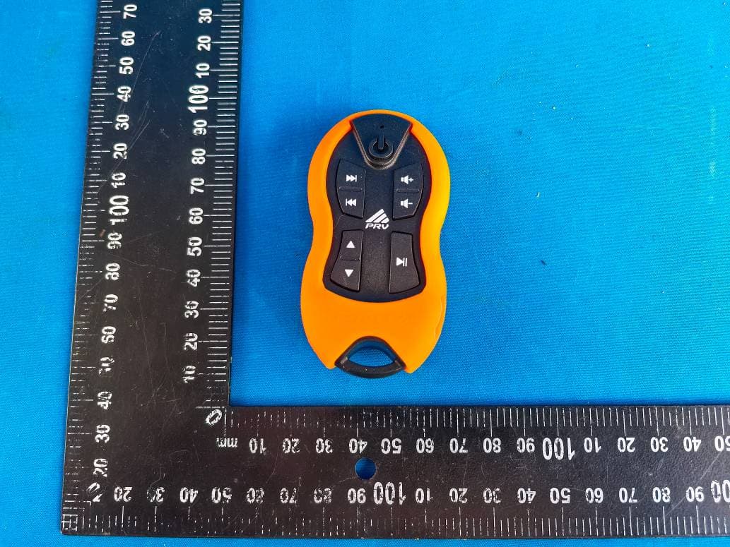
2BBF7-PRVREMOTE1500
Apr 28, 2026Remote control
Equipment Class
DSC - Part 15 Security/Remote Control Transmitter