2BBKW-MICTWireless Lavalier Microphone
SHENZHEN STARMAX AUDIO-VISUAL TECHNOLOGY CO., LTD.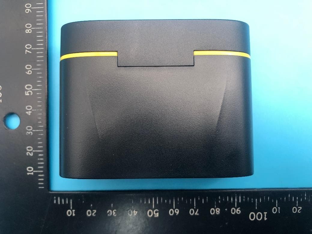
Click to zoom
Application Details
- Equipment Class
- DSS - Part 15 Spread Spectrum Transmitter
- Date of Grant
- Jun 29, 2023
- Application Purpose
- Original Equipment
- Date of Application
- Jun 29, 2023
- Equipment Note
- Wireless Lavalier Microphone
- Frequency Range
- 2402.00000000 - 2480.00000000
- Country
- China
Documents & Files
Document Text
Text extracted from the exhibit documents filed with the FCC. Open a document above to read the original.
Users Manual
(注:Type C耳机不标配,请自行购买。) 指示灯说明 发射器 发射器和接收器未配对 发射器和接收器配对成功 低电量 充电中 充满电 静音 混响开启 降噪开启 红白灯交替闪烁 白灯常亮 红灯闪烁 红灯常亮(充电时) 红灯熄灭(充电时) 红灯常亮 橙灯常亮 绿灯常亮 发射器和接收器未配对 发射器和接收器配对成功 红白灯交替闪烁 白灯常亮 说明指示灯状态 接收器 说明指示灯状态 其他 参数规格 包装信息 (1)发射器 (2)接收器 (3)充电线 (4)使用说明书 (注:充电仓和防风帽为选配,请以具体型号为准。) 安全警告 禁止拆解、撞击、挤压或者投入火中。 若出现严重鼓胀,请勿继续使用。 请勿置于高温环境中。 电池浸水后禁止使用! 本产品含有细小配件,请置于儿童接触不到的地方,以免误吞造成窒息危险。 无线传输 频率响应范围 指向性 传输距离 电池容量 2.4GHz自适应 20Hz-20KHz 全指向 ≤20米 发射器: 105mAh 1拖1充电仓: 230mAh 1拖2充电仓: 500mAh 续航发射器: 8H 充电时长 发射器: 1.5H 1拖1充电仓: 1H 1拖2充电仓: 2H 使用方法 1 连接接收器 将接收器的插头接入手机接口。 注:手机低电量时,可以通过 接收器的充电口给手机充电。 微信扫码查看安装视频教程 常见问题 1. 为什么连接手机后无法正常录音? 请检查发射器和接收器的指示灯是否显示正常。 请检查发射器电量是否充足,若低电量,请及时充电。 部分品牌手机如VIVO/OPPO/Realme需要在设置中打开OTG连接功能, 路径参考如下: (注: 下方为常规路径,请联系品牌手机厂商来获取更精确的OTG设置帮助。) 打开手机的 选项。设置 步骤1 进入 ,或在搜索栏搜索 。 步骤2步骤3 启用 连接。其他设置OTGOTG . 存储空间 日期 默认键盘 截屏 录屏 近期任务 OTG连接 备份&恢复 出厂设置 谷歌 设置 其他设置 三星 Galaxy C9 pro Galaxy Note 8 Galaxy S8 W2018 Galaxy A50/505 Galaxy A60/605 Galaxy M30s Galaxy A6s CC9 Pro X60/X60 Pro Q/Q2/V3/V5/X2/X50 Oneplus 3T Oneplus 5T Oneplus 6/ 6T Oneplus 8T Nova 2/2 s Nova 2 Plus Mate 20 Pro XPERIA Series LG G55E LG V20 一加 华为 小米 realme vivo 索尼 LG 注: 此处仅列出部分不兼容的机型,请联系品牌手机厂商来获取更 多的OTG支持机型信息。 声音清晰 远距离收音广泛兼容超长续航 降噪模式即插即用 微信扫码关注公众号,查看视频安装教程 常见问题 4. 在进行录音时,如何降低外界的噪音? 启用发射器的降噪模式。 5. 录音时连接的手机低电量该怎么办? 请将充电线连接到接收器的充电口,即可为手机充电。 2. 麦克风无法为设备自带的相机App录音? 部分品牌手机的系统出于严苛的限制,阻止了麦克风获取音频权限,并非麦 克风的质量原因。若出现这种情况,请和品牌手机厂家联系。 3. 什么是耳返监听? 本产品支持吗? 本产品兼容市面上绝大多数App,请尝试使用其他App替代。 耳返监听是指通过耳机将麦克风录制的声音实时播放,以达到监听录音效 果的目的。 若购买了配有防风帽的型号,请把防风帽安装在发射器上。 请合理调整发射器与发声源的距离,避免破音。 本产品支持耳返监听,操作流程如下: 在设备正常工作状态下,将Type C耳机接入发射器的充电口,即可监听到发 声源的录音状态。 领夹式无线麦克风 使用说明书 产品说明 发射器 (麦克风) 2 3 6 4 5 1 指示灯 1 2 电源按钮 3 降噪按钮 4 内置麦克风 5 充电口 6 背夹 操作说明 手动开/关机 长按发射器的电源按钮3秒。 开启降噪模式 单击发射器的降噪按钮,此时指示灯为绿色。 开启混响模式 在普通模式下,单击发射器的电源按钮,此时指示灯为黄色。 开启静音模式 双击发射器的电源按钮,此时指示灯为红色。 返回普通模式 在其他模式下,单击发射器的电源按钮,此时指示灯为白色。 电源按钮 降噪按钮 电源按钮 降噪按钮 使用方法 2 启动发射器 长按3秒电源按钮,发射器开机后会自动与接收器配对。 3S 佩戴示意 使用方法 3 佩戴发射器 将发射器佩戴在领口处,即可开始录音。 10 LED数显 11 充电口 产品说明 *充电仓为选配,请以具体型号为准。 充电仓 10 11 指示灯说明 充电仓 说明指示灯状态 代表充电仓当前的百分比电量 发射器充电中 数字 柱子闪烁 产品说明 接收器 苹果插头 (适用苹果设备) Type C插头 (适用安卓设备) 7 8 9 7 插头 8 充电口 9 指示灯 尺寸和重量 发射器: 20.6 x 16.0 x 47.9mm; 11.0g 接收器: 24.4 x 9.9 x 47.9mm; 5.4g 1拖1充电仓: 59.3 x 32.1 x 62.0mm; 45.6g 1拖2充电仓: 83.0 x 32.1 x 62.0mm; 65.9g *插头类型请以具体的型号为准。 *充电仓为选配,请以具体型号为准。 背面 Indicator Description Transmi er Transmi er and receiver are not paired. Transmi er and receiver paired successfully. Low ba ery. Charging. Fully charged. Mute. Reverb mode is on. Noise-cancelling mode is on. Blinks red and white alternately Solid white Blinks red Solid red (when charging) Red lights o (when charging) Solid red Solid orange Solid green Transmi er and receiver are not paired. Transmi er and receiver paired successfully. Blinks red and white alternately Solid white DescriptionIndicator Status Receiver DescriptionIndicator Status How to Use 1 Connect the receiver Plug the receiver into the smartphone’s port. Note: When the smartphone’s ba ery is low, charge the smartphone through the receiver’s charging port. Scan the QR code to get video and other support. FAQs 1. Why microphone can not record after connecting to smartphone? Check the indicators status of transmi er and receiver. Charge the transmi er if it is low power. Some smartphone brands such as VIVO/OPPO/Realme need to enable OTG connection in the se ings, the usual path reference is as follows. (Note: Please contact the smartphone manufacturer to get support on OTG se ing when having trouble finding the path.) Enter the phone. Se ings Step 1 Enter or search for in the search bar. Step 2Step 3 Enable Connection. Other Se ings OTG OTG Storage Date Default keyboard Screenshot Record Screen Recent Tasks OTG Connection Backup & Restore Factory Se ings Google Se ings Other Se ings WIRELESS LAVALIER MICROPHONE User Manual Overview Transmi er(mic) Back of the transmi er 2 3 6 4 5 1 Indicator 1 2 Power Bu on 3 Noise-cancelling Bu on 4 Built-in Microphone 5 Charging Port 6 Clip Operating Instructions Power on/o the transmi er Press and hold the transmi er’s power bu on for 3 seconds. Turn on noise-cancelling mode Click the transmi er’s noise-cancelling bu on, the indicator turns green. Turn on reverb mode Under normal mode, click the transmi er’s power bu on, the indicator turns yellow. Turn on the mute mode Double-click the transmi er’s power bu on, the indicator turns red. Return to normal mode When in other modes, click the transmi er’s power bu on, the indicator turns white. Power bu on Noise-cancelling bu on Power Bu on Noise-cancelling Bu on How to Use 2 Power on the transmi er Press and hold the power bu on for 3 seconds, and the transmi er will automatically pair with the receiver after powering on. 3S Overview How to Use 3 Record Wear the transmi er properly and start to record. 10 Digital LED Display 11 Charging Port Overview *Charging case is optional, please refer to the specific model. Charging Case 10 11 Clear Voice Long RangeWide CompatibilityLong Ba ery Life Noise CancellingPlug and Play Scan the QR code to get video and other support. FAQs 5. What should I do if the smartphone’s ba ery is low when recording? Charge the smartphone by connecting the charging cable to receiver’s charging port. 4. How to reduce noise while recording? Enable Noise-cancelling mode of the transmi er. If you have purchased a model equipped with a windscreen, please install the windscreen on the transmi er. Please adjust the distance between the transmi er and the sound source properly. *Note: The product does not include Type C headphones. 2. Why microphone can not record for the phone’s own camera app? The system of some smartphones prevents the microphone from ge ing audio permissions due to severe restrictions. If this happens, please contact the smartphone manufacturer. 3. What is in-ear monitoring? Does this product support it? Try other apps instead. This product is compatible with most apps. In-ear monitoring allows you to hear the sound recording by the microphone through earphones. This product supports in-ear monitoring, th…
Text truncated - open the document above for the full version.
Attestation Statements
SHENZHENSTARMAXAUDIO-VISUALTECHNOLOGYCO.,LTD. 2023/6/15 EurofinsElectricalandElectronicTestingNA,Inc. 914WestPatapscoAvenue Baltimore,MD21230 RE:AttestationStatementsPart2.911(d)(5)(i)requestfor(FCCID:2BBKW-MICT) ShanghaiUnihertzE-CommerceCo.,Ltd(“theapplicant”)certifiesthattheequipment forwhichauthorizationissoughtisnot“covered”equipmentprohibitedfromreceiving anequipmentauthorizationpursuanttosection2.903oftheFCCrules. Sincerely, Signature: Lvweifa SHENZHENSTARMAXAUDIO-VISUALTECHNOLOGYCO.,LTD. 2023/6/15 EurofinsElectricalandElectronicTestingNA,Inc. 914WestPatapscoAvenue Baltimore,MD21230 RE:AttestationStatementsPart2.911(d)(5)(ii)requestfor(FCCID:2BBKW-MICT) ShanghaiUnihertzE-CommerceCo.,Ltd(“theapplicant”)certifiesthat,asofthedateof thefilingoftheapplication,theapplicantisnotidentifiedontheCoveredListasan entityproducing“covered”equipment. Sincerely, Signature: Lvweifa
Block Diagram
MIC LED ANT 24MHZ Charge 3.7V-Li battery JL6976 KEY
Cover Letter(s)
SHENZHENSTARMAXAUDIO-VISUAL TECHNOLOGYCO.,LTD. Signature 2023-06-15 EurofinsElectricalandElectronicTestingNA,Inc. 914WestPatapscoAvenue Baltimore,MD21230 RE:LETTEROFAGENTAUTHORIZATION ToWhomItMayConcern: We,theundersigned,herebyauthorize(ShenzhenLGTTestServiceCo.,Ltd.)toactonour behalfinallmattersrelatingtoapplicationforequipmentauthorization,includingthesigningof alldocumentsrelatingtothesematters. Wealsoherebycertifythatnopartytotheapplicationauthorizedhereunderissubjecttothe denialofbenefits,includingFCCbenefits,pursuanttoSection5301oftheAnti-DrugAbuseAct of1988,21U.S.C.853(a). Thisagreementexpiresoneyearfromthecurrentdate. Sincerely, :Date: 2023-06-15 Name: Lvweifa Title: Productdirector Company: SHENZHENSTARMAXAUDIO-VISUALTECHNOLOGYCO.,LTD.
Cover Letter(s)
SHENZHENSTARMAXAUDIO-VISUAL TECHNOLOGYCO.,LTD. OfficeofEngineeringTechnology FederalCommunicationsCommission 7435OaklandMillsRoad Columbia,MD21046 USA Date:2023-06-15 Subject;RequestforConfidentiality FCCID:2BBKW-MICT ToWhomItMayConcern, PursuanttotheprovisionsoftheCommission’srulesTitle47Sections§0.457and§0.459,weare requestingtheCommissiontowithholdthefollowingattachment(s)asconfidentialdocumentsfrompublic disclosureindefinitely. Thesedocumentscontaindetailedsystemandequipmentdescriptionsandareconsideredasproprietary informationinoperationoftheequipment.Thepublicdisclosureofthesedocumentsmightbeharmfulto ourcompanyandwouldgivecompetitorsanunfairadvantageinthemarket. SchematicDiagram BlockDiagram OperationalDescription Tune-upProcedure PartList PCBLayout SOFTWARESECURITYREQUIREMENTSFORU-NIIDEVICES Inadditionaltoabovementioneddocuments,inordertocomplywiththemarketingregulationsinTitle47 CFR§2.803andtheimportationrulesinTitle47CFR§2.1204,whileensuringthatbusinesssensitive informationremainsconfidentialuntiltheactualmarketingofnewlyauthorizeddevices,werequestShort TermConfidentialityofthefollowingattachment(s); ExternalPhotos TestSetupPhotos InternalPhotos UserManual For45days,pursuanttoPublicNoticeDA04-1705. OR For180dayspursuanttoKDB726920D01. Itisourunderstandingthatallmeasurementtestreports,FCCIDlabelformatandcorrespondenceduring thecertificationreviewprocesscannotbegrantedasconfidentialdocumentsandthisinformationwillbe availableforpublicreviewoncethegrantofequipmentauthorizationisissued. Sincerely, Signature: Name:Lvweifa/SHENZHENSTARMAXAUDIO-VISUALTECHNOLOGYCO.,LTD. Title:Productdirector
External Photos
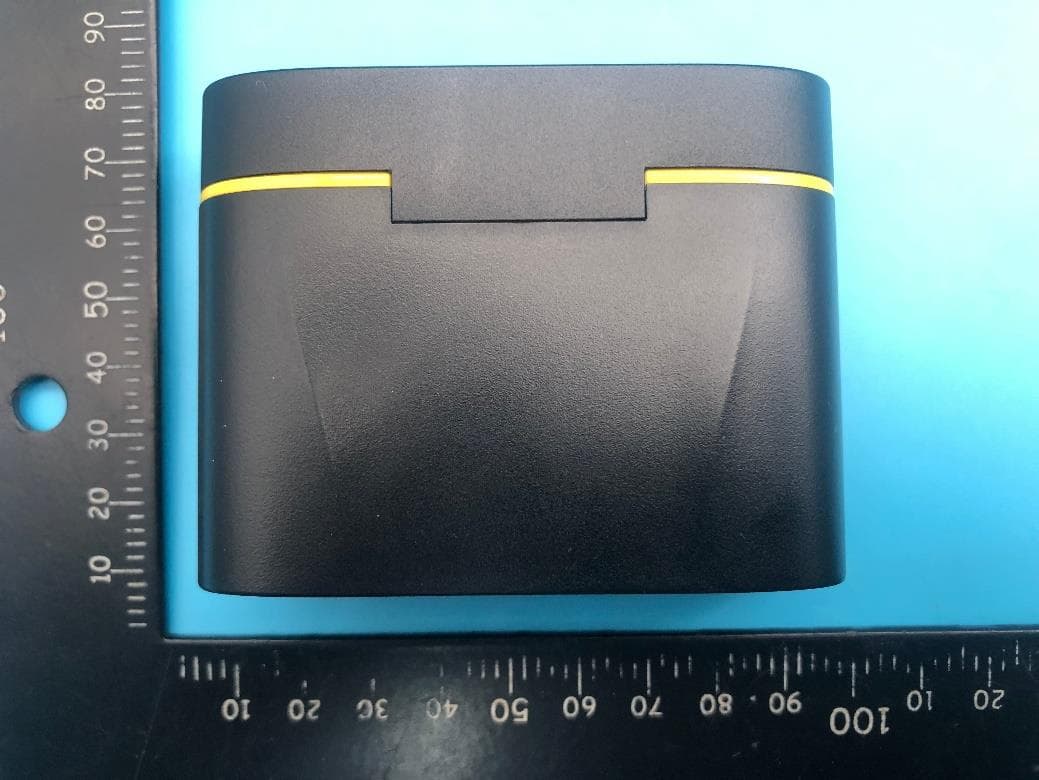
Page 1 of 7 Report No.: LGT23F001RF01 Appendix - External Photographs of EUT Constructional Details Model: M6 Pro Photo 1 Photo 2 Page 2 of 7 Report No.: LGT23F001RF01 Photo 3 Photo 4 Page 3 of 7 Report No.: LGT23F001RF01 Photo 5 Photo 6 Page 4 of 7 Report No.: LGT23F001RF01 Photo 7 Photo 8 Page 5 of 7 Report No.: LGT23F001RF01 Photo 9 Photo 10 Page 6 of 7 Report No.: LGT23F001RF01 Photo 11 Photo 12 Page 7 of 7 Report No.: LGT23F001RF01 Photo 13
ID Label/Location Info
FCC ID:2BBKW-MICT
Internal Photos
Page 1 of 2 Report No.: LGT23F001RF01 Appendix - Internal Photographs of EUT Constructional Details Model: M6 Pro Photo 1 Photo 2 BT ANT Page 2 of 2 Report No.: LGT23F001RF01 Photo 3 Photo 4
RF Exposure Info
FCC ID: 2BBKW-MICT RF EXPOSURE EVALUATION METHOD SAR Test Exclusion Thresholds for 100 MHz – 6 GHz and ≤ 50 mm Approximate SAR Test Exclusion Power Thresholds at Selected Frequencies and Test Separation Distances are illustrated in the following Table. Note: 10-g Extremity SAR Test Exclusion Power Thresholds are 2.5 times higher than the 1-g SAR Test Exclusion Thresholds indicated above. These thresholds do not apply, by extrapolation or other means, to occupational exposure limits. The 1-g and 10-g SAR test exclusion thresholds for 100 MHz to 6 GHz at test separation distances ≤ 50 mm are determined by: [(max. power of channel, including tune-up tolerance, mW)/(min. test separation distance, mm)] · [√f(GHz)] ≤ 3.0 for 1-g SAR and ≤ 7.5 for 10-g extremity SAR,where f(GHz) is the RF channel transmit frequency in GHz Power and distance are rounded to the nearest mW and mm before calculation The result is rounded to one decimal place for comparison The test exclusions are applicable only when the minimum test separation distance is ≤ 50 mm and for transmission frequencies between 100 MHz and 6 GHz. When the minimum test separation distance is < 5 mm, a distance of 5 mm is applied to determine SAR test exclusion. FCC ID: 2BBKW-MICT Bluetooth Mode Bluetooth Detector PEAK GFSK -1±1dBm π/4-DQPSK 0±1dBm GFSK2.441-0.360 1 0.3125 3 π/4-DQPSK2.4410.521 1.258925412 0.3934 3 Protocol Limit Maximum Peak Conducted Output Power (dBm) frequency (GHz) Tune up Power (dBm) Tune up Power (mW) Result Remark: Threshold at which no SAR required is 0.3934≤ 3 for 1-g SAR, Separation distance is 5mm.
Test Report
2.4GHz3216ChipAntenna:RANT3216F245C03 _ Application: WLAN,802.11b/g,Bluetooth,WLAN,etc... Features SMD,highreliability,ultraImpact,Omni-directional... PartnumberInformation RANT3216F245C03 (A)(B)(C)(D)(E)(F) ElectricalSpecification ThespecificationisdefinedonEVB. DimensionandTerminalConfiguration No.TerminalName 1Feeding/GNG 2GND/Feeding (A)ProductTypeChipAntenna (B)SizeCode 3.2x1.6mm( ± 0.2mm) (C)MaterialHighKmaterial (D)Frequency2.4~2.5GHz (E)FeedingmodePIFA&SingleFeeding (F)AntennatypeType=03 WorkingFrequencyRange2400~2500MHz Bandwidth120MHz(Min.) PeakGain2.25dBi(Typ.) Impedance50Ohm Returnloss10dB(Min) PolarizationLinear AzimuthBeamwidthOmni-directional OperationTemperature(°C)-40~85°C ResistancetoSolderingHeats 10sec.(@280°C) TerminationNi/Au(Leadless) Dimension(mm) L 3.20±0.20 W 1.60±0.20 T 0.45±0.20 咏成國際科技有限公司電話: RAINInternationalTechnologyCo.,Ltd.TEL: 2.4GHz3216ChipAntenna:RANT3216F245C03 _ 1 EvaluationBoardReference 长条板 PCB 推荐 Dimension 圆板 AntennaLayoutReference Unit:mm ElectricalCharacteristics ReturnLoss&Radiation ReturnLoss Frequency(MHz) S11(dB) 2400-10.50 2450-30.62 2500-11.47 2.4GHz3216ChipAntenna:RANT3216F245C03 _ Radiation 2400MHz2450MHz2500MHz Efficiency82.52%85.26%83.01% PeakGain1.15dBi1.24dBi1.19dBi Directivity1.89dBi1.97dBi1.91dBi X Y Z 2400MHz 2450MHz 2500MHz 2.4GHz3216ChipAntenna:RANT3216F245C03 _ TapingSpecifications ReelandTapingSpecification ReelSpecification TYPESIZEABCD 32167”5K/Reel 9.0±0.5 60±213.5±0.5178±2 TappingSpecification PackagingTypeABWEFGHTψDP PaperType3216 1.90±0.2 0 3.50±0.2 0 8.0±0.2 0 1.75±0.1 0 3.5±0.054.0±0.102.0±0.050.75±0.1 0 1.50±0.1 0 4.0±0.1 2.4GHz3216ChipAntenna:RANT3216F245C03 _ ReliabilityTable TestItemProcedure Requirements CeramicType Remark (Reference) Electrical Characterization Fulfilltheelectrical specification UserSpec. Thermal Shock 1.Preconditioning: 50±10°C/1hr,thenkeepfor24±1hrsatroomtemp. 2.Initialmeasure:Spec:referInitialspec. 3.Rapidchangeoftemperaturetest: -30°Cto+85°C;100cycles; 15minutesatLowercategorytemperature; 15minutesatUppercategorytemperature. NoVisibleDamage. Fulfilltheelectrical specification. MIL-STD-202 107 Temperature Cycling 1.Initialmeasure:Spec:referInitialspec. 2.100Cycles(-30°Cto+85°C),SoakMode=1(2Cycle/hours). 3.Measurementat24±2Hoursaftertestcondition. NoVisibleDamage. Fulfilltheelectrical specification. JESD22 JA104 HighTemperature Exposure 1.Initialmeasure:Spec:referInitialspec. 2.Unpowered;500hours@T=+85°C. 3.Measurementat24±2hoursaftertest. NoVisibleDamage. Fulfilltheelectrical specification. MIL-STD-202 108 LowTemperature Storage 1.Initialmeasure:Spec:referInitialspec. 2.Unpowered:500hours@T=-30°C. 3.Measurementat24±2hoursaftertest. NoVisibleDamage. Fulfilltheelectrical specification. MIL-STD-202 108 Solderability (SMDBottomSide) Dippingmethod: a.Temperature:235±5°C b.Dippingtime:3±0.5s Thesoldershouldcover over95%ofthecritical areaofbottomside. IEC60384-21/22 4.10 SolderingHeat Resistance (RSH) Preheatingtemperature:150±10°C. Preheatingtime:1~2min. Soldertemperature:260±5°C. Dippingtime:5±0.5s NoVisibleDamage.IEC60384-21/22 4.10 Vibration5g'sfor20min.,12cycleseachof3orientations Note:Use8"X5"PCB.031"thick7securepointson,onelong sideand2securepointsatcornersofoppositesides.Parts mountedwithin2"fromanysecurepoint.Testfrom10-2000 Hz. NoVisibleDamage.MIL-STD-202 Method204 Mechanical Shock Threeshocksineachdirectionshallbeappliedalongthethree mutuallyperpendicularaxesofthetestspecimen(18shocks) Peakvalue:1,500g’s Duration:0.5ms Velocitychange:15.4ft/s Waveform:Half-sine NoVisibleDamage.MIL-STD-202 Method213 Humidity Bias 1.Humidity:85%R.H.,Temperature:85±2°C. 2.Time:500±24hours. 3.Measurementat24±2hrsaftertestcondition. NoVisibleDamage. Fulfilltheelectrical specification. MIL-STD-202 Method106 2.4GHz3216ChipAntenna:RANT3216F245C01 _ Board Flex (SMD) 1.Mountingmethod: IR-Reflow.PCBSize(L:100×W:40×T:1.6mm) 2.Applytheloadindirectionofthearrowuntilbendingreaches 2mm. NoVisibleDamage.AEC-Q200 005 AdhesionForceof1.8Kgfor60seconds.NoVisibleDamage Magnificationof20Xor greatermaybeemployed forinspectionofthe mechanicalintegrityofthe devicebodyterminalsand body/terminaljunction. AEC-Q200 006 Physical Dimension Anyapplicablemethodusingx10magnification,micrometers, calipers,gauges,contourprojectors,orothermeasuring equipment,capableofdeterminingtheactualspecimen dimensions. Inaccordancewith specification. JESD22 JB100 RevisionHistory RevisionDateContent 12019/03/01NewDatasheet 22020/02/22Add2Dradiationcharacteristic
Test Report
The test report is effective only with both signature and specialized stamp. This report shall not be reproduced except in full without the written approval of the Laboratory. The results in this report only apply to the tested sample. Shenzhen LGT Test Service Co., Ltd. Tel: 0755-89668180 E-mail:[email protected] Web: www.lgt-cert.com Room 205, Building 13, Zone B, Zhenxiong Industrial Park, No.177, Renmin West Road, Jinsha, Kengzi Street, Pingshan District, Shenzhen, Guangdong, China RF TEST REPORT Product Name: Wireless Lavalier Microphone Model Name: M5, M6, M7, M8, M9, M10, M20, M5 Pro, M6 Pro, M7 Pro, M8 Pro, M9 Pro, M10 Pro, M20 Pro, MX, MX Pro, MXs, MXS, MX Ultra, MX Max, MX Plus, MWX (X: 1~1000) FCC ID: 2BBKW-MICT Issued For : SHENZHEN STARMAX AUDIO-VISUAL TECHNOLOGY CO., LTD. 3104, Building 2, Huasheng Longyue Tower, Jinglong Community, Longhua Street, Longhua District, Shenzhen, China Issued By : Shenzhen LGT Test Service Co., Ltd. Room 205, Building 13, Zone B, Zhenxiong Industrial Park, No.177, Renmin West Road, Jinsha, Kengzi Street, Pingshan District, Shenzhen, Guangdong, China Report Number: LGT23F001RF01 Sample Received Date: Jun. 05, 2023 Date of Test: Jun. 05, 2023 ~ Jun. 15, 2023 Date of Issue: Jun. 15, 2023 Report No.: LGT23F001RF01 Page 2 of 70 TEST REPORT CERTIFICATION Applicant: SHENZHEN STARMAX AUDIO-VISUAL TECHNOLOGY CO., LTD. Address: 3104, Building 2, Huasheng Longyue Tower, Jinglong Community, Longhua Street, Longhua District, Shenzhen, China Manufacturer: SHENZHEN STARMAX AUDIO-VISUAL TECHNOLOGY CO., LTD. Address: 3104, Building 2, Huasheng Longyue Tower, Jinglong Community, Longhua Street, Longhua District, Shenzhen, China Product Name: Wireless Lavalier Microphone Trademark: N/A Model Name: M5, M6, M7, M8, M9, M10, M20, M5 Pro, M6 Pro, M7 Pro, M8 Pro, M9 Pro, M10 Pro, M20 Pro, MX, MX Pro, MXs, MXS, MX Ultra, MX Max, MX Plus, MWX (X: 1~1000) Sample Status: Normal APPLICABLE STANDARDS STANDARD TEST RESULTS FCC Part 15.247, Subpart C ANSI C63.10-2013 PASS Prepared by: Approved by: Zane Shan Vita Li Engineer Technical Director Report No.: LGT23F001RF01 Page 3 of 70 Table of Contents Page 1. SUMMARY OF TEST RESULTS 6 1.1 TEST FACTORY 7 1.2 MEASUREMENT UNCERTAINTY 7 2. GENERAL INFORMATION 8 2.1 GENERAL DESCRIPTION OF THE EUT 8 2.2 DESCRIPTION OF THE TEST MODES 10 2.3 FREQUENCY HOPPING SYSTEM REQUIREMENTS 10 2.4 TABLE OF PARAMETERS OF TEST SOFTWARE SETTING 12 2.5 DESCRIPTION OF NECESSARY ACCESSORIES AND SUPPORT UNITS 12 2.6 EQUIPMENTS LIST 13 3. EMC EMISSION TEST 14 3.1 CONDUCTED EMISSION MEASUREMENT 14 3.2 RADIATED EMISSION MEASUREMENT 18 4. CONDUCTED SPURIOUS & BAND EDGE EMISSION 29 4.1 LIMIT 29 4.2 TEST PROCEDURE 29 4.3 TEST SETUP 30 4.4 EUT OPERATION CONDITIONS 30 4.5 TEST RESULTS 30 5. NUMBER OF HOPPING CHANNEL 31 5.1 LIMIT 31 5.2 TEST PROCEDURE 31 5.3 TEST SETUP 31 5.4 EUT OPERATION CONDITIONS 31 5.5 TEST RESULTS 31 6. AVERAGE TIME OF OCCUPANCY 32 6.1 LIMIT 32 6.2 TEST PROCEDURE 32 6.3 TEST SETUP 32 6.4 EUT OPERATION CONDITIONS 32 6.5 TEST RESULTS 32 7. HOPPING CHANNEL SEPARATION MEASUREMEN 33 7.1 LIMIT 33 7.2 TEST PROCEDURE 33 Report No.: LGT23F001RF01 Page 4 of 70 Table of Contents Page 7.3 TEST SETUP 33 7.4 EUT OPERATION CONDITIONS 33 7.5 TEST RESULTS 33 8. BANDWIDTH TEST 34 8.1 LIMIT 34 8.2 TEST PROCEDURE 34 8.3 TEST SETUP 34 8.4 EUT OPERATION CONDITIONS 34 8.5 TEST RESULTS 34 9. OUTPUT POWER TEST 35 9.1 LIMIT 35 9.2 TEST PROCEDURE 35 9.3 TEST SETUP 35 9.4 EUT OPERATION CONDITIONS 35 9.5 TEST RESULTS 35 10. ANTENNA REQUIREMENT 36 10.1 STANDARD REQUIREMENT 36 10.2 EUT ANTENNA 36 APPENDIX I:TEST RESULTS 37 DWELL TIME 37 DUTY CYCLE 42 MAXIMUM PEAK CONDUCTED OUTPUT POWER 46 -20DB BANDWIDTH 47 OCCUPIED CHANNEL BANDWIDTH 50 CARRIER FREQUENCIES SEPARATION 53 BAND EDGE 56 BAND EDGE(HOPPING) 60 CONDUCTED RF SPURIOUS EMISSION 64 NUMBER OF HOPPING CHANNEL 69 Report No.: LGT23F001RF01 Page 5 of 70 Revision History Rev. Issue Date Contents 00 Jun. 15, 2023 Initial Issue Report No.: LGT23F001RF01 Page 6 of 70 1. SUMMARY OF TEST RESULTS Test procedures according to the technical standards: KDB 558074 D01 15.247 Meas Guidance v05r02. FCC Part 15.247, Subpart C Standard Section Test Item Judgment Remark 15.207 Conducted Emission PASS -- 15.247(a)(1) Hopping Channel Separation PASS -- 15.247(a)(1)&(b)(1) Output Power PASS -- 15.209 Radiated Spurious Emission PASS -- 15.247(d) Conducted Spurious & Band Edge Emission PASS -- 15.247(a)(1)(iii) Number of Hopping Frequency PASS -- 15.247(a)(1)(iii) Dwell Time PASS -- 15.247(a)(1) Bandwidth PASS -- 15.205 Restricted bands of operation PASS -- Part 15.247(d)/part 15.209(a) Band Edge Emission PASS -- 15.203 Antenna Requirement PASS -- NOTE: (1) ‘N/A’ denotes test is not applicable in this Test Report. (2) All tests are according to ANSI C63.10-2013. Report No.: LGT23F001RF01 Page 7 of 70 1.1 TEST FACTORY Company Name: Shenzhen LGT Test Service Co., Ltd. Address: Room 205, Building 13, Zone B, Zhenxiong Industrial Park, No.177, Renmin West Road, Jinsha, Kengzi Street, Pingshan District, Shenzhen, Guangdong, China Accreditation Certificate A2LA Certificate No.: 6727.01 FCC Registration No.: 746540 CAB ID: CN0136 1.2 MEASUREMENT UNCERTAINTY The reported uncertainty of measurement y ± U, where expended uncertainty U is based on a standard uncertainty multiplied by a coverage factor of k=2, providing a level of confidence of approximately 95 %. No. Item Uncertainty 1 RF output power, conducted ±0.68dB 2 Unwanted Emissions, conducted ±2.988dB 3 All emissions, radiated 9K-30MHz ±2.84dB 4 All emissions, radiated 30M-1GHz ±4.39dB 5 All emissions, radiated 1G-6GHz ±5.10dB 6 All emissions, radiated>6G ±5.48dB 7 Conducted Emission (9KHz-150KHz) ±2.79dB 8 Conducted Emission (150KHz-30MHz) ±2.80dB Note: The measurement uncertainty is not included in the test result. Report No.: LGT23F001RF01 Page 8 of 70 2. GENERAL INFORMATION 2.1 GENERAL DESCRIPTION OF THE EUT Product Name: Wireless Lavalier Microphone Trademark: N/A Model Name: M6 Pro Series…
Text truncated - open the document above for the full version.
Test Setup Photos
Page 1 of 2 Report No.: LGT23F001RF01 Appendix - Test Setup photos Radiated Spurious Emission Test Setup Photo - Below 1GHz Radiated Spurious Emission Test Setup Photo - Above 1GHz Page 2 of 2 Report No.: LGT23F001RF01 Conducted Emission Test Setup Photo
Contact Information
Applicant
Lv weifa
Test Firm
Shenzhen LGT Test Service Co., Ltd.Wen Wen
[email protected]0755-89668180
Technical Specifications
| # | Rule Parts | Frequency Range | Power Output |
|---|---|---|---|
| 1 | 15C | 2.40 GHz - 2.48 GHz | 1.13 mW |
Other Applications from SHENZHEN STARMAX AUDIO-VISUAL TECHNOLOGY CO., LTD.
2BBKW-MICR
Jun 29, 2023Wireless Lavalier Microphone
Equipment Class
DSS - Part 15 Spread Spectrum Transmitter