2BBR2-RC100Wireless Bluetooth Microphone
MyTek Corp.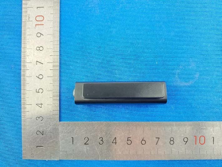
Click to zoom
Application Details
- Equipment Class
- DTS - Digital Transmission System
- Date of Grant
- Aug 19, 2023
- Application Purpose
- Original Equipment
- Date of Application
- Aug 16, 2023
- Equipment Note
- Wireless Bluetooth Microphone
- Frequency Range
- 2402.00000000 - 2480.00000000
- Company
- MyTek Corp.
- Country
- China
Documents & Files
Document Text
Text extracted from the exhibit documents filed with the FCC. Open a document above to read the original.
Users Manual
v1.0 Content list ●RichChip Microphone ●Charging cable ●Type-C to 3.5mm Cable ●Microphone Pouch ●Windshield Muff ●Storage box ●Use Manual RichChip Bluetooth Microphone Device Information Caution To ensure safety when using the product, the user should observe the following precautions: ● Keep out of reach of small children and pets. ● Do not disassemble the device by yourself, which will void the warranty. ● Keep the device away from water, moisture, solvents, or other wet surfaces. ● Do not expose the device to heat or direct sunlight. ● Only operate the device in the ideal temperature range 0°C (32°F) to 50°C (122°F). If the temperature is outside this range, unplug/power off the unit until the temperature returns to the ideal range. ● It is recommended that you clean the device with dry cloth to avoid accumulation of dirt. Never use soap or harsh cleaners. ● Do not open, damage, or expose the battery to conductive objects (such as metal), moisture, liquids, fire, or heat. Otherwise, battery fluid may leak or explode, resulting in personal injury. Battery life varies with usage. Charge RichChip Microphone 1.Connecting RichChip with the Type-C to USB charging cable, and connect to a power supply. 2.When charging, a steady RED light will show on the indicator. 3.When the indicator turns to GREEN light, the battery charge is complete. Note: please fully charging the battery when you first use Richchip Use RichChip Microphone Power on Press and hold the power button for 3 seconds till BLUE light flashes for 3 times. ● If the BLUE light and the RED light flash alternately, it means the device is waiting to be paired. ● If BLUE light flashes every 6 seconds, it means B20 is already paired to a device. Power off Press and hold the power button for 3 seconds till RED light flashes for 3 times. Then the indicator light is off. Connect RichChip Microphone via Bluetooth 1.Place RichChip next to the phone within 20 inch / 0.5 m. 2.Press and hold RichChip's power button for 3 seconds to turn on device. 3.If RichChip is waiting for pairing, BLUE and RED light will flash alternatively. 4.If RichChip is already paired, BLUE light will flash every 6 seconds. 5.Go to Bluetooth setting of the phone. Turn on Bluetooth function and search for RichChip. Click on RichChip to connect. 6.Once the connection is complete, RichChip will flash blue light every 6 seconds. NOTE: If RichChip cannot successfully connect to the phone, please connect both RichChipBLE and RichChip in the Bluetooth pairing settings of the phone. Reactivate App if B20BLE cannot be found in the device list. Disconnect the RichChip ● Temporarily - press the hold RichChip's power button for 3 seconds to turn off RichChip. The connection will be temporarily off. Press the hold the power button for 3 seconds to turn back on. The connection will resume. ● Permanently - go to Bluetooth setting of the phone. Click on RichChip and click on “Forget this device” or “Disconnect”. Troubleshooting If you encounter problems when using the RichChip, please follow the steps in the table below before contacting technical support. ProblemCauseSolution I cannot turn on RichChip. The battery is low. Charge Devie with supplied charging cable for at least 2 hours. There is no sound. The device doesn't pair with RichChip. The connection between RichChip and the device is unstable. Keep transmission distance within 15 meters. Wall or building blocked the signal. Make sure the area is clear. There is too much ambient noise. The ambient noise is too loud. Use App. Increase Gain and record again. I cannot pair R_Chip with my device. Bluetooth is disabled in your device. Enable Bluetooth in your device. The device cannot find Richchip. Device is connected withanother device. Permanently disconnect d from another device. RichChip constantly disconnects from the device. The battery is low. Charge R_chip with supplied charging cable for at least 2 hrs . LED Indicators IndicatorStatus Red light flashes for 3 timesPower off Blue light flashes for 3 timesPower on Steady red lightCharging Steady green lightFully charged Blue light flashes every 6 secondsPaired Blue light and red light flashes alternatively Waiting for pairing Weight: 16 g Bluetooth distance: 15 meters (49 feet) line of sight. Microphone type: Omnidirectional Frequency range: 25 ~ 22K Hz (microphone sensor) Sensitivity: -37dB +-1dB S/N ratio : 66dB Built-in battery: 170 mAh Charge time: <2 hours Input voltage: 5V Charging port: USB-C Voltage range : 1.65V – 3.6V Specifications Reconnect Device This device complies with part 15 of the FCC Rules. Operation is subject to the following two conditions:(1) This device may television reception, which can be determined by turning the equipment off and on, the user is encouraged to try to correct condition without restriction. The device has been evaluated to meet general RF exposure requirement. The device can be used in portable exposure - Consult the dealer or an experienced radio/TV technician for help. - Connect the equipment into an outlet on a circuit different from that to which the receiver is connected. - Increase the separation between the equipment and receiver. - Reorient or relocate the receiving antenna. the interference by one or more of the following measures: that interference will not occur in a particular installation. If this equipment does cause harmful interference to radio or not cause harmful interference, and (2) this device must accept any interference received, including interference that may accordance with the instructions, may cause harmful interference to radio communications. However, there is no guarantee installation. This equipment generates uses and can radiate radio frequency energy and, if not installed and used in FCC Rules. These limits are designed to provide reasonable protection against harmful interference in a residential This equipment has been tested and found to comply with the limits for a Class B digital device, pursu…
Text truncated - open the document above for the full version.
Attestation Statements
Oasis Compliance, Inc. FCC ID:2BBR2-RC100 CFR47§2.911(d)(7)FCCUSAgentLetterofAttestation To:FederalCommunicationsCommissio Date: 08-01-2023 FCC ID: 2BBR2-RC100 n 7435OaklandMillsRoad Columbia,MD21046 ToWhomItMayConcern, ThisletteristoconfirmthatwehaveacceptedtheresponsibilitytoactasUSAgentonbehalf ofMyTekCorp.(“theapplicant”)fortheabovereferencedFCCID. Weareawareoftherequirementsandresponsibilitiesoftheapplicant’sagentforserviceof processasoutlinedintheFCCsection2.911(d)(7)andReportandOrderFCC22-84paragraph 63. U.S.AgentInformation: OasisCompliance,Inc. FRN:0033464157 JamesHe 3313VerdiDr,SanJose,CA95111 Cell:2026028330 Sincerelyyours, JamesHe GlobalMarketAccessManager OasisCompliance,Inc. Email:[email protected]
Attestation Statements
C5266091_X24_Ed.2 1/1 “Attestation Statements” TO: Office of Engineering Technology Federal Communications Commission 7435 Oakland Mills Road Columbia, MD 21046 The Commission adopted rules that prohibit equipment authorization for “covered” telecommunications equipment and video surveillance equipment produced by entities identified on the Commission’s Covered List 1 , which is periodically updated. See the Covered List for more details. This Attestation Statement is to confirm that we follow the Section 2.911(d)(5)(i)-(ii) Applicant Company name: MyTek Corp. Grantee code: 2BBR2 FCC ID: 2BBR2-RC100 Contact Name: Mark Lee Address: 6F., No.659, Bannan Rd., Zhonghe Dist., New Taipei City 23557, Taiwan (R.O.C.) Telephone No: +886-2223 2890#233 Fax No: +886-2-8228-7286 Email: [email protected] i. [MyTek Corp.] (“the applicant”) certifies that the equipment for which authorization is sought is not “covered” equipment prohibited from receiving an equipment authorization pursuant to section 2.903 of the FCC rules. The applicant must sign this certification. ii. [ MyTek Corp.] (“the applicant”) certifies that, as of the date of the filing of the application, the applicant is not (as a specifically named entity or any of its subsidiaries or affiliates) identified on the Covered List as an entity producing “covered” equipment. The applicant must sign this certification. MyTek Corp. certifies that, as of the date of the filing of the application, the applicant is not identified on the Covered List as an entity producing “covered” equipment. Date: 8.1 4.2023 Applicant’s Name: Mark Lee Title: Product Manager Signature 1 The Commission’s Covered List is published by the Public Safety and Homeland Security Bureau and posted on the Commission’s website. This Covered List, which is periodically updated, identifies particular equipment, produced by particular entities, that constitutes “covered” equipment. https://www.fcc.gov/supplychain/coveredlist
Attestation Statements
CFR47§2.911(d)(7)AgentDesignationAttestation To:FederalCommunicationsCommissio Date: 08-01-2023 FCC ID: 2BBR2-RC100 n 7435OaklandMillsRoad Columbia,MD21046 MyTekCorp.(“theapplicant”)asrequiredbysection2.911(d)(7),designatesthefollowing agent,locatedintheUnitedStates,forpurposesofactingastheapplicant’sagentforservice ofprocess. Theapplicantacknowledgesthattheywillmaintainanagentfornolessthanoneyearafterthe granteehasterminatedallmarketingandimportationortheconclusionofanyCommission- relatedproceedinginvolvingtheequipment.Theapplicantfurtheracknowledgestheir responsibilitytoinformtheFCCwhenevertheagentinformationchanges. U.S.AgentInformation: JamesHe OasisCompliance,Inc. 3313VerdiDr,SanJose,CA95111 [email protected] cell:2026028330 Sincerelyyours, MarkLee Manager MyTekCorp. Address:6F.,No.659,BannanRd.,ZhongheDist.,NewTaipeiCity23557,Taiwan(R.O.C.) Email:[email protected] Phone:+886-22232890#233
Cover Letter(s)
C5266091_X8_Ed.1 1/1 Letter of Authorization Company: MyTek Corp. Address: 6F., No.659, Bannan Rd., Zhonghe Dist., New Taipei City 23557, Taiwan (R.O.C.) Product Name: Wireless Bluetooth Microphone Model Number: RC100 FCC Identifier: 2BBR2-RC100 We authorize LGAI Technological Center S.A., Ronda de la Font del Carme, s/n, 08193 Bellaterra, Spain, to act on our behalf on all matters concerning the above named equipment. Any individual within LGAI Technological Center S.A. is authorized to act on our behalf and take action on the application. We declare that authorize LGAI Technological Center S.A., Ronda de la Font del Carme, s/n, 08193 Bellaterra, Spain, is allowed to forward all information related to the approval project to the Federal Communication Commission and to discuss any issues concerning the approval application. Any and all acts carried out by LGAI Technological Center S.A. on our behalf shall have the same effect as acts of our own. Name: Mark Lee Date: 8/14/2023 Title: Product Manager Signature of applicant:
Cover Letter(s)
C5266091_X10_Ed.1 1/1 MyTek Corp. Office of Engineering Technology Federal Communications Commission 7435 Oakland Mills Road Columbia, MD 21046 Date: 8/14/2023 Subject: Request for Confidentiality FCC ID: 2BBR2-RC100 To Whom It May Concern, Pursuant to the provisions of Sections 0.457 and 0.459 of Commission's rules (47CFR0.457, 0.459), we are requesting the Commission to withhold the following attachment(s) as confidential document from public disclosure. Exhibits Long-Term Confidentiality Short-Term Confidentiality ID Label/Location No No Attestation Statement No No External Photos No Block Diagram Schematics Test Report No No Test Setup Photos No User’s Manual Internal Photos Parts List / Tune Up RF Exposure Info Operational Description Cover Letter(s) No No SDR Software / Security Info No Above mentioned document contains detailed system and equipment description are considered as proprietary information in operation of the equipment. The public disclosure of above documents might be harmful to our company and would give competitor an unfair advantage in the market. It is our understanding that all measurement test reports, FCC ID label format and correspondent during certification review process cannot be granted as confidential documents and those information will be available for public review once the grant of equipment authorization is issued. Sincerely, Signature: Name: Mark Lee Date: 8/14/2023 Title: Product Manager
External Photos
External Appendix Model: RC100
ID Label/Location Info
Label Si ze: 22*10mm Location
RF Exposure Info
Address: 101, No. 7, Zone 2, Xinxing Industrial Park, Fuhai Avenue, Xinhe Community, Fuhai Street, Bao’an District, Shenzhen, Guangdong, China. Tel: (86-755)88850135 Fax: (86-755) 88850136 Web: www.mtitest.com E-mail: [email protected] RF EXPOSURE Test Report Report No.: MTi230606003-05E3 Date of issue: 2023-07-17 Applicant: MyTek Corp. Product: Wireless Bluetooth Microphone Model(s): RC100 FCC ID: 2BBR2-RC100 Shenzhen Microtest Co., Ltd. http://www.mtitest.com - Page 2 of 6- Report No.: MTi230606003-05E3 Address: 101, No. 7, Zone 2, Xinxing Industrial Park, Fuhai Avenue, Xinhe Community, Fuhai Street, Bao’an District, Shenzhen, Guangdong, China. Tel: (86-755)88850135 Fax: (86-755) 88850136 Web: www.mtitest.com E-mail: [email protected] Instructions 1. The report shall not be partially reproduced without the written consent of the laboratory; 2. The test results of this report are only responsible for the samples submitted; 3. This report is invalid without the seal and signature of the laboratory; 4. This report is invalid if transferred, altered or tampered with in any form without authorization; 5. Any objection to this report shall be submitted to the laboratory within 15 days from the date of receipt of the report. - Page 3 of 6- Report No.: MTi230606003-05E3 Address: 101, No. 7, Zone 2, Xinxing Industrial Park, Fuhai Avenue, Xinhe Community, Fuhai Street, Bao’an District, Shenzhen, Guangdong, China. Tel: (86-755)88850135 Fax: (86-755) 88850136 Web: www.mtitest.com E-mail: [email protected] Applicant: MyTek Corp. Address: 6F., No.659, Bannan Rd., Zhonghe Dist., New Taipei City 23557, Taiwan (R.O.C.) Manufacturer: MyTek Corp. Address: 6F., No.659, Bannan Rd., Zhonghe Dist., New Taipei City 23557, Taiwan (R.O.C.) Product description Product name: Wireless Bluetooth Microphone Trademark: RichChip Model name: RC100 Serial Model: N/A Standards: N/A Test method: KDB 447498 D01 v06 Date of Test Date of test: 2023-06-20 ~ 2023-06-27 Test result: Pass Test Engineer : (Maleah Deng) Reviewed By: : (Leon Chen) Approved By: : (Tom Xue) - Page 4 of 6- Report No.: MTi230606003-05E3 Address: 101, No. 7, Zone 2, Xinxing Industrial Park, Fuhai Avenue, Xinhe Community, Fuhai Street, Bao’an District, Shenzhen, Guangdong, China. Tel: (86-755)88850135 Fax: (86-755) 88850136 Web: www.mtitest.com E-mail: [email protected] Table of Contents 1. STANDALONE SAR TEST EXCLUSION CONSIDERATIONS ............................................................................................ 5 2. SAR TEST EXCLUCSION THRESHOLDS ........................................................................................................................ 6 - Page 5 of 6- Report No.: MTi230606003-05E3 Address: 101, No. 7, Zone 2, Xinxing Industrial Park, Fuhai Avenue, Xinhe Community, Fuhai Street, Bao’an District, Shenzhen, Guangdong, China. Tel: (86-755)88850135 Fax: (86-755) 88850136 Web: www.mtitest.com E-mail: [email protected] 1. Standalone SAR test exclusion considerations Unless specifically required by the published RF exposure KDB procedures, standalone 1-g head or body and 10-g extremity SAR evaluation for general population exposure conditions, by measurement or numerical simulation, is not required when the corresponding SAR Test Exclusion Threshold condition(s), listed below, is (are) satisfied. These test exclusion conditions are based on source-based time-averaged maximum conducted output power of the RF channel requiring evaluation, adjusted for tune-up tolerance, and the minimum test separation distance required for the exposure conditions. The minimum test separation distance defined in 4.1 f) is determined by the smallest distance from the antenna and radiating structures or outer surface of the device, according to the host form factor, exposure conditions and platform requirements, to any part of the body or extremity of a user or bystander. To qualify for SAR test exclusion, the test separation distances applied must be fully explained and justified, typically in the SAR measurement or SAR analysis report, by the operating configurations and exposure conditions of the transmitter and applicable host platform requirements, according to the required published RF exposure KDB procedures. When no other RF exposure testing or reporting are required, a statement of justification and compliance must be included in the equipment approval, in lieu of the SAR report, to qualify for SAR test exclusion. When required, the device specific conditions described in the other published RF exposure KDB procedures must be satisfied before applying these SAR test exclusion provisions. a) For 100 MHz to 6 GHz and test separation distances ≤ 50 mm, the 1-g and 10-g SAR test exclusion thresholds are determined by the following: [(max. power of channel, including tune-up tolerance, mW) / (min. test separation distance, mm)] · [√f(GHz)] ≤ 3.0 for 1-g SAR, and ≤ 7.5 for 10-g extremity SAR, where f (GHz) is the RF channel transmit frequency in GHz Power and distance are rounded to the nearest mW and mm before calculation The result is rounded to one decimal place for comparison The values 3.0 and 7.5 are referred to as numeric thresholds in step b) below The test exclusions are applicable only when the minimum test separation distance is ≤ 50 mm, and for transmission frequencies between 100 MHz and 6 GHz. When the minimum test separation distance is < 5 mm, a distance of 5 mm according to 4.1 f) is applied to determine SAR test exclusion. b) For 100 MHz to 6 GHz and test separation distances > 50 mm, the 1-g and 10-g SAR test exclusion thresholds are determined by the following (also illustrated in Appendix B): 1) {[Power allowed at numeric threshold for 50 mm in step a)] + [(test separation distance – 50 mm)·(f(MHz)/150)]} mW, for 100 MHz to 1500 MHz 2) {[Power allowed at numeric threshold for 50 mm in step a)] + [(test separation distance – 50 mm)·10]} mW, for > 1500 MHz and ≤ 6 GHz c) For frequencies below 100 MHz, the following may be consid…
Text truncated - open the document above for the full version.
Test Report
© Unictron Techn All specifications ologies Corp. subject to change without notice. 5F., No. 83, Kewang Rd., Longtan Dist., Taoyuan City 32556, Taiwan (R.O.C.) Tel: 886-3- 4072728|Fax: 886-3-4072738 |[email protected] 1 www.uni www. ct sanav ron.com .com Product Name: WiFi/Bluetooth Chip Antenna – CW201 Part Number: H2U34C1H1B0100 Features: Supporting WiFi/Bluetooth, covering 2400 to 2484 MHz Surface Mount Dimensions: 2.0 x 1.2 x 0.6 mm High performance, small size. RoHS & REACH & HF Compliant AEC-Q200 Compliant Applications: ISM 2.4 GHz applications ZigBee/BLE applications Bluetooth earphone systems Unictron Technologies Corp. 2021-10-08 Document Control Center Hand-held devices when WiFi / Bluetooth functions are needed, e.g., Smart phones IEEE802.11 b/g/n 2 www w .u w n w ic . t s r a o n n a .c v o .c m om Unictron Technologies Corp. 2021-10-08 Document Control Center WiFi/Bluetooth Chip Antenna MODEL: CW201 Version: H I. Specifications: Items Specifications Frequencies (MHz) 2400~2484 Return loss (dB) < -10 Typ. Efficiency (%) 62 Typ. Average Gain (dB) -2.1 Typ. Peak Gain (dBi) 2.1 Typ. Test Condition 40 x 20 mm² (Evaluation board) Impedance (Ω) 50 Polarization Linear Polarization Mechanical Specifications Dimensions (mm) 2.0(L) x 1.2 (W) x 0.6 (H) Material Ceramic Termination Ag (environmental Pb free) Environmental Conditions Operation Temperature ( o C) -40 ~ +85 Storage Temperature ( o C) -5 ~ +40 Relative Humidity 10 ~ 70 % 5F., No. 83, Kewang Rd., Longtan Dist., Taoyuan City 32556, Taiwan (R.O.C.) Tel: 886-3- 4072728|Fax: 886-3-4072738 |[email protected] © Unictron Technologies Corp. All specifications subject to change without notice. 3 www w .u w n w ic . t s r a o n n a .c v o .c m om Grounding Pin Signal Input Unictron Technologies Corp. 2021-10-08 Document Control Center II. Layout Guide: Solder Land Pattern: The solder land pattern (gold marking areas) is shown below. Recommendation on matching circuit will be provided according to customer’s installation conditions. Top View Transmission Line with 50Ω Impedance Characteristic Bottom View 5F., No. 83, Kewang Rd., Longtan Dist., Taoyuan City 32556, Taiwan (R.O.C.) Tel: 886-3- 4072728|Fax: 886-3-4072738 |[email protected] © Unictron Technologies Corp. All specifications subject to change without notice. 4 www w .u w n w ic . t s r a o n n a .c v o .c m om Unictron Technologies Corp. 2021-10-08 Document Control Center III. Mechanical Dimensions: a) Antenna Dimensions Side View Unit: mm b) PIN Definition Unit: mm PIN 1 2 Soldering Pad Signal Input Tuning/Signal Output 5F., No. 83, Kewang Rd., Longtan Dist., Taoyuan City 32556, Taiwan (R.O.C.) Tel: 886-3- 4072728|Fax: 886-3-4072738 |[email protected] TOP View Bottom View © Unictron Technologies Corp. All specifications subject to change without notice. 5 www w .u w n w ic . t s r a o n n a .c v o .c m om Unit: mm Unictron Technologies Corp. 2021-10-08 Document Control Center c) Test Board with Antenna 5F., No. 83, Kewang Rd., Longtan Dist., Taoyuan City 32556, Taiwan (R.O.C.) Tel: 886-3- 4072728|Fax: 886-3-4072738 |[email protected] © Unictron Technologies Corp. All specifications subject to change without notice. 6 www w .u w n w ic . t s r a o n n a .c v o .c m om Unictron Technologies Corp. 2021-10-08 Document Control Center IV. Properties: a) Return loss (dB) b) Efficiency (%) 5F., No. 83, Kewang Rd., Longtan Dist., Taoyuan City 32556, Taiwan (R.O.C.) Tel: 886-3- 4072728|Fax: 886-3-4072738 |[email protected] © Unictron Technologies Corp. All specifications subject to change without notice. 7 www w .u w n w ic . t s r a o n n a .c v o .c m om Unictron Technologies Corp. 2021-10-08 Document Control Center c) Average Gain (dB) d) Peak Gain (dBi) 5F., No. 83, Kewang Rd., Longtan Dist., Taoyuan City 32556, Taiwan (R.O.C.) Tel: 886-3- 4072728|Fax: 886-3-4072738 |[email protected] © Unictron Technologies Corp. All specifications subject to change without notice. 8 www w .u w n w ic . t s r a o n n a .c v o .c m om Y Z X Unictron Technologies Corp. 2021-10-08 Document Control Center V. Antenna Radiation Pattern Measurement: The antenna radiation patterns are measured in Unictron’s 3D Anechoic Chamber. The measurement setup is as show below. 5F., No. 83, Kewang Rd., Longtan Dist., Taoyuan City 32556, Taiwan (R.O.C.) Tel: 886-3- 4072728|Fax: 886-3-4072738 |[email protected] © Unictron Technologies Corp. All specifications subject to change without notice. 9 www w .u w n w ic . t s r a o n n a .c v o .c m om Z X Y Unictron Technologies Corp. 2021-10-08 Document Control Center 3D Radiation Gain Pattern 2450 MHz (unit: dBi) 5F., No. 83, Kewang Rd., Longtan Dist., Taoyuan City 32556, Taiwan (R.O.C.) Tel: 886-3- 4072728|Fax: 886-3-4072738 |[email protected] © Unictron Technologies Corp. All specifications subject to change without notice. 10 www w .u w n w ic . t s r a o n n a .c v o .c m om System Matching Circuit Component Location Description Vendor Tolerance 1 N/C - - 2 5.0 pF (0402) MURATA ±0.05 pF 3 0.8 pF (0402) MURATA ±0.05 pF 4 2.7 pF (0201) MURATA ±0.05 pF DC Block 22 pF (0402) MURATA ±5% 4 2 3 1 DC Block Unictron Technologies Corp. 2021-10-08 Document Control Center VI. Frequency tuning: 5F., No. 83, Kewang Rd., Longtan Dist., Taoyuan City 32556, Taiwan (R.O.C.) Tel: 886-3- 4072728|Fax: 886-3-4072738 |[email protected] © Unictron Technologies Corp. All specifications subject to change without notice. 11 www w .u w n w ic . t s r a o n n a .c v o .c m om Control Center VII. Soldering conditions: Typical Soldering Profile for Lead-free Process VIII. Reminders for use of Unictron’s ceramic chip antennas: a) This chip antenna is made of ceramic materials which is relatively more rigid and brittle compared to circuit board materials. Furthermore, the length of this antenna is quite long. Bending of circuit board at the locations where chip antenna is mounted may cause the cracking of solder joints or antenna itself. b) Punching/c…
Text truncated - open the document above for the full version.
Test Report
Address: 101, No. 7, Zone 2, Xinxing Industrial Park, Fuhai Avenue, Xinhe Community, Fuhai Street, Bao’an District, Shenzhen, Guangdong, China Tel: (86-755)88850135 Fax: (86-755) 88850136 Web: www.mtitest.com E-mail: [email protected] Test Report Report No.: MTi230606003-05E1 Date of issue: 2023-07-17 Applicant: MyTek Corp. Product: Wireless Bluetooth Microphone Model(s): RC100 FCC ID: 2BBR2-RC100 Shenzhen Microtest Co., Ltd. http://www.mtitest.com Page 2 of 60 Report No.: MTi230606003-05E1 Address: 101, No. 7, Zone 2, Xinxing Industrial Park, Fuhai Avenue, Xinhe Community, Fuhai Street, Bao’an District, Shenzhen, Guangdong, China Tel: (86-755)88850135 Fax: (86-755) 88850136 Web: www.mtitest.com E-mail: [email protected] Instructions 1. This test report shall not be partially reproduced without the written consent of the laboratory. 2. The test results in this test report are only responsible for the samples submitted 3. This test report is invalid without the seal and signature of the laboratory. 4. This test report is invalid if transferred, altered, or tampered with in any form without authorization. 5. Any objection to this test report shall be submitted to the laboratory within 15 days from the date of receipt of the report. Page 3 of 60 Report No.: MTi230606003-05E1 Address: 101, No. 7, Zone 2, Xinxing Industrial Park, Fuhai Avenue, Xinhe Community, Fuhai Street, Bao’an District, Shenzhen, Guangdong, China Tel: (86-755)88850135 Fax: (86-755) 88850136 Web: www.mtitest.com E-mail: [email protected] Table of contents 1 General Description ........................................................................................................................... 5 1.1 Description of the EUT ............................................................................................................................... 5 1.2 Description of test modes .......................................................................................................................... 5 1.3 Environmental Conditions .......................................................................................................................... 7 1.4 Description of support units ....................................................................................................................... 7 1.5 Measurement uncertainty .......................................................................................................................... 7 2 Summary of Test Result .................................................................................................................... 8 3 Test Facilities and accreditations ..................................................................................................... 9 3.1 Test laboratory ........................................................................................................................................... 9 4 List of test equipment ...................................................................................................................... 10 5 Evaluation Results (Evaluation) ..................................................................................................... 13 5.1 Antenna requirement ............................................................................................................................... 13 6 Radio Spectrum Matter Test Results (RF) ..................................................................................... 13 6.1 Conducted Emission at AC power line .................................................................................................... 13 6.2 Occupied Bandwidth ................................................................................................................................ 17 6.3 Power Spectral Density ........................................................................................................................... 20 6.4 Emissions in non-restricted frequency bands .......................................................................................... 21 6.5 Band edge emissions (Radiated)............................................................................................................. 23 6.6 Emissions in restricted frequency bands (below 1GHz) .......................................................................... 28 6.7 Emissions in restricted frequency bands (above 1GHz) ......................................................................... 32 Photographs of the test setup ............................................................................................................... 39 Photographs of the EUT ........................................................................................................................ 40 Appendix A: DTS Bandwidth ................................................................................................................. 41 Appendix B: Maximum conducted output power ................................................................................ 44 Appendix C: Maximum power spectral density ................................................................................... 47 Appendix D: Band edge measurements ............................................................................................... 50 Appendix E: Conducted Spurious Emission ....................................................................................... 52 Appendix F: Duty Cycle ......................................................................................................................... 58 Page 4 of 60 Report No.: MTi230606003-05E1 Address: 101, No. 7, Zone 2, Xinxing Industrial Park, Fuhai Avenue, Xinhe Community, Fuhai Street, Bao’an District, Shenzhen, Guangdong, China Tel: (86-755)88850135 Fax: (86-755) 88850136 Web: www…
Text truncated - open the document above for the full version.
Contact Information
Applicant
Mark Lee(Product Manager)
Technical Contact
Test Firm
Shenzhen Microtest Co., Ltd.Phoebe Cui
[email protected]0755 88850135 1393
Technical Specifications
| # | Rule Parts | Frequency Range | Power Output |
|---|---|---|---|
| 1 | 15C | 2.40 GHz - 2.48 GHz | 1.00 mW |