2BBSN-W17multifunction wireless power bank
ShenZhen SuJue Electronic Technology Co., Ltd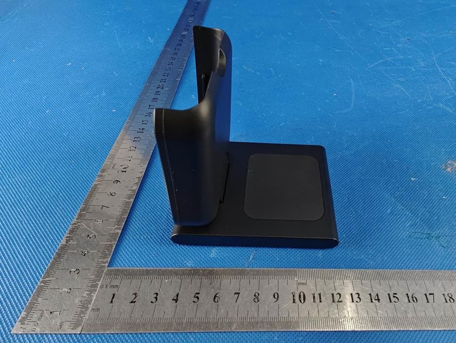
Click to zoom
Application Details
- Equipment Class
- DCD - Part 15 Low Power Transmitter Below 1705 kHz
- Date of Grant
- Jul 12, 2023
- Application Purpose
- Original Equipment
- Date of Application
- Jul 12, 2023
- Equipment Note
- multifunction wireless power bank
- Frequency Range
- 0.11300000 - 0.20500000
- Country
- China
Documents & Files
Document Text
Text extracted from the exhibit documents filed with the FCC. Open a document above to read the original.
Users Manual
中国制造/Made in China Made in China 3-IN-1 Folding Magnetic Wireless Charging Station 3-IN-1 Folding Magnetic Wireless Charging Station 三合一 折叠磁吸无线充电宝支架 无线充区域 折叠手表充电 折叠支架 磁吸位置 耳机无线充电 Type-c 输入/输出口 充电触点电源开关 电源指示灯 折叠充电底座 充电指示灯 为支持磁吸无线充功能的iPhone无线充电,请将您的设备放在 本产品上(如下图所示),磁吸装置会将设备自动定位,即可激活 无线充电。本产品自动侦测无线充放电,无需按键操作。 Folding Watch charging Wireless earbuds charging Folding Charging base Charging indicator For iPhone that supports magnetic wireless charging, please put your device on this product (as shown the figure below), the magnetic suction device will align the device in place and then activate wireless charging. This product can automatically detect wireless charging and discharging, without key operation. 放电 本体磁吸在具备磁吸无线充功能的苹果手机上,可自动实现对手机的无线充电。 充电 使用 Type-c 数据线,通过Type-c接口为充电宝充电。 可以使用配带的充电底座,通过POGOPIN(充电触点)连接为充电宝充电。 充电宝放置于充电底座上充电时,充电底座手机指示灯亮(一秒即灭)提示POGOPIN 连接正常。 当手机放在无线充电面板上会自动触发无线充电功能(无需按电量检查键)。也可以 通过以下方式开启无线充电功能: 短按电量检查键/充电宝接入充电器或充电底座 (无线充电指示灯点亮进入无线充待机模式)。 本品自身未被充电时,可以短按电量检查键开启无线充电功能如果不放入无线充电 设备,约5秒钟后自动关闭无线充电功能如放入无线充电设备工作后再移开,约5秒钟 后自动关闭无线充电功能,待充电宝进入休眠模式”后,充电宝自动检测是否有无线充 电设备接入,有无线充电设备接入时,充电宝自动开启无线充电功能,为接入的无线 充电设备充电。 注意事项 首次使用,请先将本产品充满电。 在为本产品充电或使用本产品为其他设备有线充电时,请自行选择规格适配的 充电器和充电线. 在使用本产品为其他设备无线充电时,其他设备如果有保护套,请确认保护套为非金属 材质,且厚度不得超过2mm 使用底座充电前请保持底座弹针与充电触点表面清洁无异物。 对本产品充电过程中,应确保有人在场,外出或长时间离开时请拔除电源。 本产品充满电,或本产品对其他设备充满电后,请及时将连接线拔除。使用无线充电 功能对其他设备充满电后,请及时将设备从本产品上移开,避免长时间处于连接状态产 生损耗。 如本产品按键后无电量指示,可能处于保护状态,可连接到外部充电器尝试恢复。 长时间不使用本产品时,请使本产品电量保持在约25%-50%范围,存放于阴凉干燥环境。 避免于满电或无电的状态下长期保存本产品,以延长电池寿命。 请勿与带磁条或者芯片的磁卡(身份证、银行卡等)放置太近,避免造成磁卡失效。 基本参数 Parameters 名称:三合一折叠磁吸无线充电宝支架 产品型号:W17 Type-c输入:DC 5V/3A ; DC 9V/2A Type-c输出:DC 5V/3A ; DC 9V/2A ;DC 12V/1.5A POGO PIN(充电触点)输入:2W /10W 无线充输出:5W/7.5W/10W/15W 有线输出:18W 电池容量: 5000mAh Name: Model : W17 Type-c Input:DC 5V/3A ; DC 9V/2A Type-c Output:DC 5V/3A ; DC 9V/2A ;DC 12V/1.5A POGO PIN Input :2W /10W Wireless charging input:5W/7.5W/10W/15W Wired output:18W Battery capacity : 5000mAh Wireless charging area Magnetic attraction position Type-c Input/Ouput Charging pin Power switch Power indicator Charging Use Type-c data cable to charge the power bank through Type-c interface. The attached charging base can be used to charge the power bank through the POGO PIN connection. Discharge The wireless charging function is automatically activated when the phone is placed on the wireless charging base (no need to press the power check button). You can also enable the wireless charging function by using the following methods: Press the power check button shortly or power bank access the charger or charging base(The wireless charging indicator lights up and enters the wireless charging standby mode). When the product itself is not charged, press the power check button to turn on the wireless charging function. If it is not put the wireless charging device on, the wireless charging function will be automatically turned off after about 5 seconds. If it is put the wireless charging device on and removed after working, the wireless charging function will be automatically turned off after about 5 seconds. When a wireless charging device is connected, the power bank automatically enables the wireless charging function to charge the connected wireless charging device. Tips Please charge the product full for the first time use. When charging this product or using this product to charge other devices,please choose the charger and charging cable with proper specifications. When using this product for wireless charging for other devices, if there is a protective cover for other devices, please make sure that the protective cover is made of non-metallic material, the thickness should not exceed 2mm Before use the charging base, keep the surface of the base pin and the charging pin clean. During the charging process,make sure that someone is nearby. Please remove the power when going out or leaving for a long time. After this product is fully charged or this product is fully charged to other devices, please remove the connection cable in time. After using the wireless charging function to fully charge other devices, remove the devices in time to avoid loss caused by long-term connection. If there is no power indicator after pressing the button, the product may be in the protected status, you can connect to the external charger to try recover it. If you do not use this product for a long time, please keep the power of this product in the range of 25%-50% and keep it in a cool and dry environment. To longer the battery life,please avoid to keep it full or no power status for a long time. Do not place it too close to magnetic card magnetic stripe or chip (ID card, bank card,etc.) Otherwise,the magnetic card may become invalid. On the Apple mobile phone with magnetic absorption wireless charging function, it can automatically realize wireless charging of the mobile phone. 磁吸面朝上 The magnetic side is upward 使用展示说明 折叠状态 支架状态 Folding bracket Folding status Stand status Use presentation instructions FCC Statement This device complies with part 15 of the FCC Rules. Operation is Subject To the following two conditions: (1)This device may not cause harmful interference, and (2) this device must accept any interference received, including interference that may cause undesired operation. Changes or modifications not explicitly approved by the party responsible for compliance could void the user's authority to operate this equipment. Note: this equipment has been tested and found to comply with the limits for a Class B digital device, pursuant to part 15 of the FCC Rules. These limits are designed to provide reasonable protection against harmful interference in a residential installation. This equipment generates, uses and candidate radio frequency energy and, if not installed and used in accordance with the instructions, may cause harmful interference to radio communications. However, there is no guarantee that interference will not occur in a particular installation. If this equipment does cause harmful interference…
Text truncated - open the document above for the full version.
Attestation Statements
ShenZhenSuJueElectronicTechnologyCo., Ltd Theinformationprovidedin thisletteris basedon thereferencedrulepartsof Title47 of theCFRas wellas KDB986446D01. Anexpirationdateforthisletterdoesnotexist.In casetheU.S.agentchanges,thegranteeis obligatedto notifytheFCCwithin30 daysvia thegrantingTCB. FederalCommunicationsCommission Authorizationand EvaluationDivision EquipmentAuthorizationBranch 7435 OaklandMills Road Columbia,MD 21046 7/10/23 U.S. AgentDesignation ShenZhenSuJueElectronicTechnologyCo., Ltdacknowledgestheir consentfor the following contactlocatedin the UnitedStatesto act as their agent for serviceof processfor the equipmentfor which authorizationis sought(FCC ID: 2BBSN-W17): Nameand companyof U.S. agent:Tim Payne,FCC US Agent,LLC PhysicalU.S. addressof agent:3722 IllinoisAvenue,Saint Charles,IL, 60174,USA FRN of U.S. agent:0033402884 Email addressof U.S. agent:[email protected] FCC US Agent,LLCacknowledgestheir obligationto acceptserviceof processon behalfof ShenZhenSuJueElectronicTechnologyCo., Ltd . ShenZhenSuJueElectronicTechnologyCo., Ltdwith the FRN 0033918251acceptsits obligation to maintainan agent for serviceof processin the UnitedStatesfor no less than one year after either the granteehas permanentlyterminatedall marketingand importationof the applicableequipment withinthe U.S., or the conclusionof any Commission-relatedadministrativeor judicialproceeding involvingthe equipment,whicheveris later. By signingthis form, we confirmthe aboveand that we are awareof the applicationrequirements listed under § 2.911(d)(7). Sincerely, Signature Liang Liang Su CEO ShenZhenSuJueElectronicTechnologyCo., Ltd Signature Tim Payne Manager FCC US Agent,LLC 48_[model] US_Agent_2.911(d)(7)-U, V04
External Photos
Page 1 of 4 FCC ID: 2BBSN-W17 Dongguan Yaxu (AiT) Technology Limited No.22, Jinqianling 3rd Street, Jitigang, Huangjiang, Dongguan, Guangdong, China. EUT Constructional Details External EUT Photo Photo 1 Photo 2 Page 2 of 4 FCC ID: 2BBSN-W17 Dongguan Yaxu (AiT) Technology Limited No.22, Jinqianling 3rd Street, Jitigang, Huangjiang, Dongguan, Guangdong, China. Photo 3 Photo 4 Page 3 of 4 FCC ID: 2BBSN-W17 Dongguan Yaxu (AiT) Technology Limited No.22, Jinqianling 3rd Street, Jitigang, Huangjiang, Dongguan, Guangdong, China. Photo 5 Photo 6 Page 4 of 4 FCC ID: 2BBSN-W17 Dongguan Yaxu (AiT) Technology Limited No.22, Jinqianling 3rd Street, Jitigang, Huangjiang, Dongguan, Guangdong, China. Photo 7 Photo 8 ---The End---
ID Label/Location Info
Label FCC ID: 2BBSN-W17
Internal Photos
Page 1 of 5 FCC ID: 2BBSN-W17 Dongguan Yaxu (AiT) Technology Limited No.22, Jinqianling 3rd Street, Jitigang, Huangjiang, Dongguan, Guangdong, China. EUT Constructional Details Internal EUT Photo Photo 1 Photo 2 Page 2 of 5 FCC ID: 2BBSN-W17 Dongguan Yaxu (AiT) Technology Limited No.22, Jinqianling 3rd Street, Jitigang, Huangjiang, Dongguan, Guangdong, China. Photo 3 Photo 4 Antenna Page 3 of 5 FCC ID: 2BBSN-W17 Dongguan Yaxu (AiT) Technology Limited No.22, Jinqianling 3rd Street, Jitigang, Huangjiang, Dongguan, Guangdong, China. Photo 5 Photo 6 Page 4 of 5 FCC ID: 2BBSN-W17 Dongguan Yaxu (AiT) Technology Limited No.22, Jinqianling 3rd Street, Jitigang, Huangjiang, Dongguan, Guangdong, China. Photo 7 Photo 8 Page 5 of 5 FCC ID: 2BBSN-W17 Dongguan Yaxu (AiT) Technology Limited No.22, Jinqianling 3rd Street, Jitigang, Huangjiang, Dongguan, Guangdong, China. Photo 9 ------End------
RF Exposure Info
Page 1 of 6 FCC ID: 2BBSN-W17 RF Exposure Evaluation 1 Measuring Standard KDB 680106 RF Exposure Wireless Charging Apps v03r01 2 Requirements According to the item 5 of KDB 680106 v03r01: Inductive wireless power transfer applications that meet all of the following requirements are excluded from submitting an RF exposure evaluation. (1) Power transfer frequency is less than 1MHz. (2) Output power from each primary coil is less than or equal to 15 watts. (3) The system may consist of more than one source primary coils, charging one or more clients. If more than one primary coil is present, the coil pairs may be powered on at the same time. (4) Client device is placed directly in contact with the transmitter. (5) Mobile exposure conditions only (portable exposure conditions are not covered by this exclusion). (6) The aggregate H-field strengths anywhere at or beyond 15 cm surrounding the device, and 20 cm away from the surface from all coils that by design can simultaneously transmit, and while those coils are simultaneously energized, are demonstrated to be less than 50% of the applicable MPE limit. Remark: Meet all the above requirements. Limits The criteria listed in the following table shall be used to evaluate the environment impact of human exposure to radio frequency (RF) radiation as specified in 1.1307(b) Limits for Maximum Permissible Exposure (MPE) Page 2 of 6 FCC ID: 2BBSN-W17 3 Test Setup 4 Test Procedure 1) The RF exposure test was performed in anechoic chamber. 2) The measurement probe was placed at test distance (15 cm from all sides and 20 cm from the top) which is between the edge of the charger and the geometric center of probe. 3) The highest emission level was recorded and compared with limit as soon as measurement of each points (A, B, C, D, E) were completed. 4) The EUT was measured according to the dictates of KDB 680106 D01v03. Remark:The EUT’s test position A, B, C, D and E is valid for the E and H field measurements. 5 Description of the test mode Equipment under test was operated during the measurement under the following conditions: Test Mode Description Mode 1 AC Adapter + EUT + Earphone Record Mode 2 Test the EUT in idle mode. Pre-tested Note: All test modes were pre-tested, but we only recorded the worst case in this report. Page 3 of 6 FCC ID: 2BBSN-W17 6 Peripheral List 7 Test Instruments list Test Equipment Manufacturer Model No. SN. Cal.Date (mm-dd-yy) Cal.Due date (mm-dd-yy) Electric and Magnetic Field Analyzer Narda EHP-200A 180ZX10505 22.06.2022 21.06.2024 8 Test Result E-Filed Strength at 15 cm from the edges surrounding the EUT (V/m) Unit Test mode Test Position A Test Position B Test Position C Test Position D Test Position E 50% Limits (V/m) Limits (V/m) V/m TM1 90.46 100.53 97.44 95.62 90.51 307 614 H-Filed Strength at 15 cm from the edges surrounding the EUT (A/m) Unit Test mode Test Position A Test Position B Test Position C Test Position D Test Position E 50% Limits (A/m) Limits (A/m) A/m TM1 0.235 0.244 0.201 0.220 0.235 0.815 1.63 H-Filed Strength at 20 cm from the top of the EUT (A/m) Unit Test mode Test Position E 50% Limits (A/m) Limits (A/m) A/m TM1 0.209 0.815 1.63 Note: All test modes were pre-tested, but we only recorded the worst case in this report. N o. Equipment Manufacturer Model No. Serial No. Power cord signal cable 1 Adapter HNT HNT-QC530 N/A N/A N/A 3 Earphone PocBuds K6 N/A N/A N/A Page 4 of 6 FCC ID: 2BBSN-W17 9 Test Setup photo Test Position A-15cm from the edge of EUT to the geometric center of the probe Test Position B-15cm from the edge of EUT to the geometric center of the probe Page 5 of 6 FCC ID: 2BBSN-W17 Test Position C-15cm from the edge of EUT to the geometric center of the probe Test Position D-15cm from the edge of EUT to the geometric center of the probe Page 6 of 6 FCC ID: 2BBSN-W17 Test Position E-15cm from the edge of EUT to the geometric center of the probe Test Position F-20cm from the edge of EUT to the geometric center of the probe ***End of report***
Test Report
Page 1 of 23 Report No.: AIT23062004FW1 Dongguan Yaxu (AiT) Technology Limited No.22, Jinqianling Third Street, Jitigang, Huangjiang,Dongguan, Guangdong, China. FCC TEST REPORT Client Information: Applicant: ShenZhen SuJue Electronic Technology Co., Ltd Applicant add.: 2nd floor, building B, Yuxing chuanggu, Gushu 2nd Road, Xixiang Town, Bao’an District, Shenzhen Manufacturer: ShenZhen SuJue Electronic Technology Co., Ltd Manufacturer add.: 2nd floor, building B, Yuxing chuanggu, Gushu 2nd Road, Xixiang Town, Bao’an District, Shenzhen Product Information: Product Name: multifunction wireless power bank Model No.: W17,W16,W19,W20,D7,D8,D16,D17 Brand Name: N/A FCC ID: 2BBSN-W17 Applicable standards: FCC CFR Title 47 Part 15 Subpart C Prepared By: Dongguan Yaxu (AiT) Technology Limited No.22, Jinqianling 3rd Street, Jitigang, Huangjiang,Dongguan, Guangdong, China Tel.: +86-769-8202 0499 Fax.: +86-769-8202 0495 Date of Receipt: June 20, 2023 Date of Test: June 20, 2023~ June 28, 2023 Date of Issue: June 29, 2023 Test Result: Pass This device described above has been tested by Dongguan Yaxu (AiT) Technology Limited and the test results show that the equipment under test (EUT) is in compliance with the FCC requirements. And it is applicable only to the tested sample identified in the report. Note: This report shall not be reproduced except in full, without the written approval of Dongguan Yaxu (AiT) Technology Limited, this document may be altered or revised by Dongguan Yaxu (AiT) Technology Limited, personal only, and shall be noted in the revision of the document. This test report must not be used by the client to claim product endorsement. Reviewed by: Approved by: Simba Huang Seal.chen Page 2 of 23 Report No.: AIT23062004FW1 Dongguan Yaxu (AiT) Technology Limited No.22, Jinqianling Third Street, Jitigang, Huangjiang,Dongguan, Guangdong, China. 1 Contents Page COVER PAGE 1 CONTENTS ........................................................................................................................................................... 2 2 TEST SUMMARY .................................................................................................................................................. 5 2.1 STATEMENT OF THE MEASUREMENT UNCERTAINTY ............................................................................................. 5 2.2 MEASUREMENT UNCERTAINTY ............................................................................................................................ 5 3 TEST FACILITY ..................................................................................................................................................... 6 3.1 DEVIATION FROM STANDARD ............................................................................................................................... 6 3.2 ABNORMALITIES FROM STANDARD CONDITIONS .................................................................................................... 6 3.3 TEST LOCATION ................................................................................................................................................. 6 4 GENERAL INFORMATION ................................................................................................................................... 7 4.1 EUT TEST MODE ............................................................................................................................................... 8 4.2 DESCRIPTION OF TEST SETUP............................................................................................................................. 8 4.3 PERIPHERAL LIST ............................................................................................................................................... 9 4.4 EUT PERIPHERAL LIST ....................................................................................................................................... 9 5 EQUIPMENTS LIST FOR ALL TEST ITEMS ..................................................................................................... 10 6 CONDUCTED EMISSION TEST ......................................................................................................................... 11 6.1 CONDUCTED EMISSION MEASUREMENT ................................................................................................ 11 6.2 POWER LINE CONDUCTED EMISSION LIMITS ........................................................................................... 11 6.3 TEST PROCEDURE ...................................................................................................................................... 11 6.4 DEVIATION FROM TEST STANDARD ......................................................................................................... 11 6.5 TEST SETUP ................................................................................................................................................. 12 6.6 EUT OPERATING CONDITIONS .................................................................................................................. 12 6.7 TEST RESULT .................................................................................................................................................. 13 7 RADIATED EMISSION MEASUREMENT .......................................................................................................... 15 7.1 RADIATED EMISSION LIMITS .............................................................................................................................. 15 7.2 ANECHOIC CHAMBER TEST SETUP DIAGRAM ..................................................................................................... 16 7.3 TEST PROCEDURE ........................................................................................................................................... 16 7.4 DEVIATION FROM TEST STANDARD ..............................................…
Text truncated - open the document above for the full version.
Test Report
1.AntennaDescription: Antennatype:loopcoilAntenna Manufacturer: ShenZhenSuJueElectronicTechnologyCo.,Ltd Model: W17 antenna AntennaGain(Peak):0dBi Frequencyrange:113kHz-205kHz 2.AntennaPhoto: 42mm
Test Setup Photos
Page 1 of 2 FCC ID:2BBSN-W17 Dongguan Yaxu (AiT) Technology Limited No.22, Jinqianling 3rd Street, Jitigang, Huangjiang, Dongguan, Guangdong, China. Test Setup Photo Radiated Emission Page 2 of 2 FCC ID:2BBSN-W17 Dongguan Yaxu (AiT) Technology Limited No.22, Jinqianling 3rd Street, Jitigang, Huangjiang, Dongguan, Guangdong, China. Conducted Emission ------End------
Contact Information
Applicant
Liang Liang Su
Test Firm
Dongguan Yaxu (AiT) Technology LimitedCoin Tang
[email protected]+86 0769-82020499-21
Technical Specifications
| # | Rule Parts | Frequency Range | Power Output |
|---|---|---|---|
| 1 | 15C | 0.113 MHz - 0.205 MHz | - |