2BBWS-418536Liquid Level Sensor
Biotage Sweden AB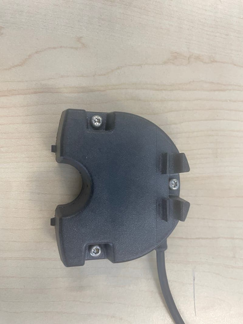
Click to zoom
Application Details
- Equipment Class
- FDS - Part 15 Field Disturbance Sensor
- Date of Grant
- Oct 04, 2023
- Application Purpose
- Original Equipment
- Date of Application
- Sep 13, 2023
- Equipment Note
- Liquid Level Sensor
- Frequency Range
- 57000.00000000 - 64000.00000000
- Company
- Biotage Sweden AB
- Country
- Sweden
Documents & Files
Document Text
Text extracted from the exhibit documents filed with the FCC. Open a document above to read the original.
Users Manual
Biotage ® Liquid Level Sensor for Biotage ® Selekt Family User Manual Patent Pending © Biotage 2023 Biotage ® Liquid Level Sensor for Biotage ® Selekt Family – User Manual | © Biotage 2023 Biotage ® Selekt Liquid Level Sensor for Biotage ® Selekt Family User Manual CONTENTS 1 Introduction 1 Biotage ® Liquid Level Sensor 1 Solvent Notifications and Stop Limits Based on Distance 1 Safety Stop Limit for Waste 1 Included in the Kit 2 Technical Specifications 3 Safety 3 Intended Use 3 Labels Used on the Biotage ® Liquid Level Sensor Kit 3 MIC Giteki Marking on Biotage ® Liquid Level Sensor 3 FCC and ISED for Biotage ® Liquid Level Sensor 4 Safety Requirements 4 Safety in Other Languages 5 Connect the Liquid Level Sensors to the System 5 Connect the Hub to the System 5 Mount the Liquid Level Sensors on the Reser voirs 6 Cable and Tube Routing 7 Connect the Liquid Levels Sensors to the Hub 7 Connections 7 Use the Universal Cap Adapter 8 Enable the Liquid Level Sensors 9 Administrate Reser voirs 9 Reservoir Parameters 9 Calibrate a Reser voir 10 Transfer Reser voirs 11 Assign Solvents and Reservoir Types 12 Status of the Liquid Level Sensors 13 Solvent and Waste Estimations and Notifications 13 Run Estimation 13 Solvent and Waste Notifications 13 Safety Stop Limit for Waste 14 Refill a Solvent and Empty Waste 14 Refill a Solvent Reser voir 14 Empty the Waste Reser voir 14 Replace a Solvent or Waste Reser voir 15 Maintenance and Troubleshooting 15 Maintenance Contents 15 Troubleshooting 16 General Information 16 Consumables and Accessories 16 Biotage ® Selekt Family User Documentation 16 Manufacturer 16 Contact Us 16 Intellectual Property 17 Safety Translations 17 安全について 18 Sécurité 19 Seguridad 20 Sicherheitshinweise 21 Sicurezza 22 Sikkerhed 23 Säkerhet 24 Turvallisuus 25 Veiligheid 1 Introduction Introduction Biotage ® Liquid Level Sensor Using radar technology, Biotage ® Liquid Level Sensor measures the distance between the sensor (mounted on the reser voir cap) and the liquid level, enabling the system to present the actual amount of liquid available in the reser voir in real time. With the liquid level sensor hub installed on your Selekt or Selekt Enkel system, and its functionality enabled in the system settings, the sensors can be used to monitor the liquid levels in the solvent reser voirs and/or the waste reser voir connected to your system (see Figure 1). For the reser voirs to be used with the liquid level sensors, they must be defined and calibrated in the Reservoir Administration view. The software comes with two preconfigured reser voirs supplied by Biotage. Custom reser voirs can be defined and calibrated on one system and transferred to other Selekt and Selekt Enkel systems using a USB memor y device or network share (if enabled). Reser voirs are assigned to the solvent inlets and waste outlet in the Solvent Setup view; see page 11. The status of the connected liquid level sensors is displayed both in the Solvent Setup view and the About view (see page 12). Figure 1 Biotage ® Liquid Level Sensor Hub Biotage ® Liquid Level Sensor . Selekt system with Biotage ® Liquid Level Sensor used on all solvent reservoirs and the waste reservoir. All the liquid level sensors are connected to Biotage ® Liquid Level Sensor Hub. Solvent Notifications and Stop Limits Based on Distance The solvent notifications and stop limits are based on the distance between the solvent surface and the bottom of the reser voir. This optimizes how much solvent that can be used without the risk of aspirating air. For more information, see page 13. Safety Stop Limit for Waste To ensure that the waste reser voir cannot be overfilled, the pump operation in progress is immediately paused if the distance between the sensor and the waste liquid becomes smaller than allowed. This is useful if e.g. the operator by mistake is using a waste reser voir that is smaller than the one that has been assigned to the solvent inlet in the software. Included in the Kit Part NumberDescriptionQty 418758Biotage ® Liquid Level Sensor Hub1 418574CAN Power Cable1 418536Biotage ® Liquid Level Sensor5/3* 418777Tube Holder5/3* 418569Waste Tube Insert4 418839Markings Kit1 418859Cable Support Clip, Solvent20 418890Cable Support Clip, Waste5 * Five are delivered with the Biotage ® Selekt Liquid Level Sensor Kit (P/N 418776) and three with the Biotage ® Selekt Enkel Liquid Level Sensor Kit (P/N 418843) . Note that the required caps are not included in the kit and have to be ordered separately, see “Consumables and Accessories” on page 16. We recommend that the boxes and packing materials are kept by the customer incase the kit needs to be shipped in the future. Note: All the system photographs and software images in this manual show the Selekt system. 2Biotage ® Liquid Level Sensor for Biotage ® Selekt Family User Manual | © Biotage 1 12 Technical Specifications Fume Hood/ Ventilation System A laboratory fume hood with the capacity to handle leakage of solvents and provide suitable airflow to prevent the build-up of flammable vapors. LocationIndoor use only. No wet locations. Biotage ® Liquid Level Sensor must be placed on a stable, and flat level surface. Ambient TemperatureOperating: 15°C to 32°C (59°F to 90°F). Storage and transportation: -25°C to 60°C (-13°F to 140°F). Humidity20% to 90% RH (non-condensing). AltitudeOperation: up to 2000 m (6562 ft). Pollution DegreeThe Biotage ® Liquid Level Sensor kit shall be installed and used in a level 2 environment in accordance with EN 60664-1. Electrical Supply24 V Max Power Consumed500 mA MaterialsPEEK (tube holder), PPS (sensor house, cap, and universal cap adapter), PP (hub), TPE partly coated with PO (sensor cable) WeightHub: 133.5 g (0.29 lbs) Sensor: 64.2 g (0.14 lbs) DimensionsHub: 157 x 85 x 32 mm (6.2" x 3.3" x 1.3") Sensor: 63 x 55 x 27 mm (2.5" x 2.2" x 1.1") IP ClassificationIP54 for the sensor RF Type (Sensor)Transceiver Operating Frequency Range 57 to 64 GHz Radar Peak Output Power 18…
Text truncated - open the document above for the full version.
Attestation Statements
___________________________________________________________________________________ Postal address Delivery address Telephone Fax Org.num. Biotage Sweden AB Box 8 Vimpelgatan 5 +46-18-56 59 00 +46-18-59 19 22 556487-4922 SE-751 03 Uppsala SE-753 18 Uppsala Sweden Sweden Biotage Sweden AB Vimpelgatan 5 753 18 Uppsala Sweden Federal Communication Commission Authorization and Evaluation Division 7435 Oakland Mills Road Columbia, MD 21046 USA 2023-07-19 Attestation Statement according to 2.911(d)(5)(i) and 2.911(d)(5)(ii) FCC ID: 2BBWS-418536 TO WHOM IT MAY CONCERN: Hereby we certify that the equipment for which authorization is sought is not “covered” equipment prohibited from receiving an equipment authorization pursuant to section 2.903 of the FCC rules. Further we certify that, as of the date of the filing of the application, Biotage Sweden AB is not identified on the Covered List as an entity producing “covered” equipment. Sincerely, _______________ (signature & company stamp) Biotage Sweden AB Vimpelgatan 5 753 18 Uppsala, Sweden Name: Bahashty Eizuldeen Phone: +46737007744 [email protected]
Cover Letter(s)
Document Version 1.1 2020-10-30 LONG-TERM CONFIDENTIALITY REQUEST for Certification Service in the USA Federal Communication Commission Equipment Authorization Division, Application Processing Branch 7435 Oakland Mills Road Columbia, MD 21048 TO WHOM IT M AY CONCERN Pursuant to Paragraphs §0.457 and 0.459 of the Commission’s Rules (47 C.F.R.) and Section §552(b)(4) of the Freedom of Information Act, we request Long-Term Confidentiality for the following product: For the product stated above, we request Long-Term Confidentiality for exhibits which contain Block Diagram, Operational Description, Parts List/Tune Up Info, Schematics, SDR Software/Security Info. The above exhibits contain ou r trade secrets and proprietary information that could be of benefit to o ur competitors. This information will not be publicly available. If you have any questions, please feel free to contact us at the address shown below. Sincerely, Company Name: Phone: Company Address: Fax: E-mail: Contact Name: Signature: Signature Date: Check your GC here. Click Grantee Search. FCC I D: Grantee Code Equipment Product Code
External Photos
Annex B No.1-5707/23-01-01 September 08, 2023 DescriptionExternal photographs of EUT This document is electronically signed and valid without handwritten signature. Public keys for verification of the electronic signatures can be requested at the testing laboratory. Authorized Meheza Walla Lab Manager Radio Labs cetecom advanced GmbH Untertürkheimer Str. 6-10, 66117 Saarbrücken Document No. 1-5707/23-01-01 Release 1 - Page 1 of 3 Photo 1 Photo 2 cetecom advanced GmbH Untertürkheimer Str. 6-10, 66117 Saarbrücken Document No. 1-5707/23-01-01 Release 1 - Page 2 of 3 Photo 3 - END OF DOCUMENT - cetecom advanced GmbH Untertürkheimer Str. 6-10, 66117 Saarbrücken Document No. 1-5707/23-01-01 Release 1 - Page 3 of 3
ID Label/Location Info
Approved by Description Revision Constructed by ECO A DF Document: Biotage Sweden AB Print layout Title Name Date: Page: System Label, Biotage ® Liquid Level Sensor 418954 2023-03-23 1(1) Model: Biotage ® Liquid Level Sensor Part no: 418536 Serial no: LLSYYWWNNNNN FCC ID: 2BBWS-418536 IC: 30950-418536 202-JKM046
Internal Photos
Annex A No.1-5707/23-01-01 September 07, 2023 DescriptionInternal photographs of EUT This document is electronically signed and valid without handwritten signature. Public keys for verification of the electronic signatures can be requested at the testing laboratory. Authorized Meheza Walla Lab Manager Radio Labs cetecom advanced GmbH Untertürkheimer Str. 6-10, 66117 Saarbrücken Document No. 1-5707/23-01-01 Release 1 - Page 1 of 5 Photo 1 Photo 2 cetecom advanced GmbH Untertürkheimer Str. 6-10, 66117 Saarbrücken Document No. 1-5707/23-01-01 Release 1 - Page 2 of 5 Photo 3 Photo 4 cetecom advanced GmbH Untertürkheimer Str. 6-10, 66117 Saarbrücken Document No. 1-5707/23-01-01 Release 1 - Page 3 of 5 Photo 5 Photo 6 cetecom advanced GmbH Untertürkheimer Str. 6-10, 66117 Saarbrücken Document No. 1-5707/23-01-01 Release 1 - Page 4 of 5 Photo 7 - END OF DOCUMENT - cetecom advanced GmbH Untertürkheimer Str. 6-10, 66117 Saarbrücken Document No. 1-5707/23-01-01 Release 1 - Page 5 of 5
RF Exposure Info
© cetecom advanced GmbH Page 1 of 2 RF Exposure Evaluation according to KDB 447498 D01 v06 Report identification number: 1-5707/23-01-08-A_MPE_FCC Certification numbers and labeling requirements FCC ID 2BBW S-418536 This test report is electronically signed and valid without handwritten signature. For verification of the electronic signatures, the public keys can be requested at the testing laboratory. Document authorised: Alexander Hnatovskiy Marco Scigliano Lab Manager Testing Manager Radio Labs Radio Labs Report no.: 1-5707/23-01-08 © cetecom advanced GmbH Page 2 of 2 1. MPE at given distance (KDB 447498 D01 General RF Exposure Guidance v06) Equation from page 18 of OET Bulletin 65, Edition 97-01 S = PG / 4 π R 2 where: S = Power density P = Power input to the antenna G = Antenna gain R = Distance to the center of radiation of the antenna PG = Output Power including antenna gain The table below is excerpted from Table 1B of 47 CFR 1.1310 titled “Limits for Maximum Permissible Exposure (MPE), Limits for General Population/Uncontrolled Exposure” Frequency Range (MHz) Power Density (mW/cm 2 ) Averaging Time (minutes) 300 -1500 f/1500 30 1500 - 100000 1.0 30 where f = Frequency (MHz) 2. EUT technologies Declared minimum safety distance: 20 cm f Min f Max # P ERP P EIRP P RF Exp S Result S Limit % 57-64 GHz 5700064000AN/A 1.61.60.00031.0000 0.03% SRD Technology Frequency [MHz] Reference Power Density [mW/cm²] Share of Limit Output Power [dBm] Referenced Documents: # Results from: A Test Report 1-5707_23-01-03, p. 31 3. Conclusion This prediction demonstrates the following: The power density levels for FCC at a distance of 20 cm are below the maximum levels allowed by regulations. Conclusion: RF exposure evaluation is not required.
Test Report
BNetzA - CAB - 02/21 - 102 TEST REPORT Test report no.: 1-5707_23-01-03 Testing laboratory Applicant cetecom advanced GmbH Untertuerkheimer Strasse 6 – 10 66117 Saarbruecken / Germany Phone: + 49 681 5 98 - 0 Fax: + 49 681 5 98 - 9075 Internet: https://cetecomadvanced.com e-mail: [email protected] Accredited Testing Laboratory: The testing laboratory (area of testing) is accredited according to DIN EN ISO/IEC 17025 (2018-03) by the Deutsche Akkreditierungsstelle GmbH (DAkkS). The accreditation is valid for the scope of testing procedures as stated in the accreditation certificate with the registration number: D-PL-12047-01-00. ISED Testing Laboratory Recognized Listing Number: DE0001 FCC designation number: DE0002 Biotage Sweden AB Vimpelgatan 5 75318 Uppsala / SWEDEN Phone: +46 18 56 59 00 Contact: Bahashty Eizuldeen e-mail: [email protected] Manufacturer Biotage Sweden AB Vimpelgatan 5 75318 Uppsala / SWEDEN Test standard/s FCC - Title 47 CFR Part 15 FCC - Title 47 of the Code of Federal Regulations; Chapter I; Part 15 - Radio frequency devices For further applied test standards please refer to section 3 of this test report. Test Item Kind of test item: Liquid level Sensor Model name: Biotage® Liquid Level Sensor FCC ID: 2BBWS-418536 Frequency: 57 GHz – 64 GHz Antenna: 2 embedded dipole antennas Power supply: 5.0 V DC by external power supply Temperature range: +15°C to +32°C This test report is electronically signed and valid without handwritten signature. For verification of the electronic signatures, the public keys can be requested at the testing laboratory. Test report authorized: Test performed: Thomas Vogler Meheza Walla Lab Manager Lab Manager Radio Labs Radio Labs Test report no.: 1-5707_23-01-03 © cetecom advanced GmbH Page 2 of 47 1 Table of contents 1 Table of contents ....................................................................................................................................... 2 2 General information ................................................................................................................................... 3 2.1 Notes and disclaimer ...................................................................................................................... 3 2.2 Application details .......................................................................................................................... 3 2.3 Test laboratories sub-contracted .................................................................................................... 3 3 Test standard/s, references and accreditations ......................................................................................... 4 4 Reporting statements of conformity – decision rule .................................................................................. 4 5 Test environment ....................................................................................................................................... 5 6 Test item ................................................................................................................................................... 5 6.1 General description ......................................................................................................................... 5 6.2 Additional information .................................................................................................................... 5 7 Description of the test setup ...................................................................................................................... 6 7.1 Shielded semi anechoic chamber .................................................................................................... 7 7.3 Radiated measurements, 18 GHz – 50 GHz ................................................................................... 11 7.4 Radiated measurements > 50 GHz ................................................................................................ 11 7.5 Radiated measurements > 50 GHz ................................................................................................ 12 8 Sequence of testing ................................................................................................................................. 14 8.1 Sequence of testing radiated spurious 9 kHz to 30 MHz ............................................................... 14 8.2 Sequence of testing radiated spurious 30 MHz to 1 GHz ............................................................... 15 8.3 Sequence of testing radiated spurious 1 GHz to 18 GHz................................................................ 16 8.4 Sequence of testing radiated spurious above 18 GHz .................................................................... 17 8.5 Sequence of testing radiated spurious above 50 GHz with external mixers ................................... 18 9 Measurement uncertainty ........................................................................................................................ 19 10 Far field consideration for measurements above 18 GHz ..................................................................... 19 11 Summary of measurement results ....................................................................................................... 20 12 Measurement results ........................................................................................................................... 21 12.1 Occupied bandwidth (10 dB bandwidth / 20 dB bandwidth / 99% bandwidth) ............................ 21 12.2 Maximum E.I.R.P. / Peak transmitter conducted output power .................................................. 24 12.3 Spurious emissions radiated ..................................................................................................... 33 12.4 Frequency Stability .................................................................................................................... 41 13…
Text truncated - open the document above for the full version.
Test Report
© Reproduction of this document, or any parts thereof, is prohibited without written permission. Author: Signature: Date: André Sihm 2023-09-07 File name: Status: Report-23-077.docx First Revision Project Project no. Date: Page: Selekt Upgrade PD0247 2023-09-07 1(3) Form/template number Edition M02-R014 AB Test Report 23-077 Biotage® Liquid Level Sensor Antenna Gain & EIRP Reviewed by: Peter Neldemo 2023-09-25 Document: Test Report Project: Project no. Date: Page: Selekt Upgrade PD0247 2023-09-07 2(3) 1 Summary From a regulatory perspective the Biotage® Liquid Level Sensor (LLS) must comply with certain radio frequency standards. Two important properties from a safety perspective are the antenna gain and the transmitter output power. Both properties determine how strong radio signal output is possible. Through measurements the antenna gain is approximated to 14 dBi and the peak Effective Isotropic Radiated Power (EIRP) to 18 dBm. 2 Scope Approximating LLS total antenna gain and EIRP through measurements. Antenna gain is the combined gain from the integrated antenna and the lens. Peak EIRP is the effective peak power output of antenna and transmitter combined. 3 Background The Biotage® LLS is a radar sensor operating at 57-61 GHz frequency using pulse modulation to detect liquid levels in solvent containers. 3.1 Radar chip The sensor uses Acconeer’s A111 radar chip which utilizes an Antenna in Package (AiP) technology. This means that the transmitter and antenna are integrated in the same chip and cannot easily be separated. Nominal values of the chip are found in Table 1. Item Value Source Transmitter output power 10 dBm [1] Antenna gain 6 dBi [2] Table 1. Acconeer A111 radar output properties. 3.2 Lens The sensor uses a Fresnel Zone Plate (FZP) lens integrated into the sensor housing. 3.3 References No. Title Source [1] A111 Datasheet developer.acconeer.com/download/a111-datasheet-pdf/ [2] Antenna Datasheet v1.1 - 4 Equipment and methods The antenna gain is defined as the total gain stemming from the integrated radar chip antenna in combination with the FZP lens integrated in the Sensor housing. Or, as an equation: 퐺 푡표푡푎푙 = 퐺 푎푛푡푒푛푛푎 + 퐺 푙푒푛푠 ( 1 ) Where G antenna is 6 dBi found in [2] and G lens is calculated according to: 퐺 푙푒푛푠 =0.5∗20∗푙표푔10∗ 퐴푚푝푙푖푡푢푑푒 퐿푒푛푠 퐴푚푝푙푖푡푢푑푒 푛표 퐿푒푛푠 ( 2 ) Where amplitude with and without lens is measured with an LLS connected to an LLS hub through UDP-test. To measure the amplitude the sensor was aimed at an aluminum cylinder Document: Test Report Project: Project no. Date: Page: Selekt Upgrade PD0247 2023-09-07 3(3) with a circumference of 50 mm at a distance of 300 mm. The amplitude was measured with and without the housing with integrated lens. Peak EIRP is approximated according to: 퐸퐼푅푃 푝푒푎푘 = 푃 푡푟푎푛푠푚푖푡푡푒푟 + 퐺 푙푒푛푠 ( 3 ) 5 Results As the measured amplitude fluctuates over time, an average during a 10 s period was used. Measuring the amplitude yielded the following: - Without lens: 400 units - With lens 2500 units With this as input to Equation (2) the following gain is obtained: 퐺 푙푒푛푠 =10∗푙표푔10∗ 퐴푚푝푙푖푡푢푑푒 퐿푒푛푠 퐴푚푝푙푖푡푢푑푒 푛표 퐿푒푛푠 =10∗푙표푔10 ( 2500 400 ) =7.96≈ 8 dB Which then in turn is used as input to Equation (1) results in a total gain of: 퐺 푡표푡푎푙 = 퐺 푎푛푡푒푛푛푎 + 퐺 푙푒푛푠 =8+6=14 푑퐵푖 Finally Peak EIRP is approximated through (3) as: 퐸퐼푅푃 푝푒푎푘 = 푃 푡푟푎푛푠푚푖푡푡푒푟 + 퐺 푙푒푛푠 =10 푑퐵푚+8 푑퐵=18 푑퐵푚 6 Discussion and conclusion In conclusion, through measurements the following is approximated: • Antenna gain: G total ≈14 dBi • EIRP peak ≈ 18 dBm
Test Setup Photos
Annex D No.1-5707/23-01-01 September 08, 2023 DescriptionTest set-up photographs This document is electronically signed and valid without handwritten signature. Public keys for verification of the electronic signatures can be requested at the testing laboratory. Authorized Meheza Walla Lab Manager Radio Labs cetecom advanced GmbH Untertürkheimer Str. 6-10, 66117 Saarbrücken Document No. 1-5707/23-01-01 Release 1 - Page 1 of 5 Photo 1 Photo 2 cetecom advanced GmbH Untertürkheimer Str. 6-10, 66117 Saarbrücken Document No. 1-5707/23-01-01 Release 1 - Page 2 of 5 Photo 3 Photo 4 cetecom advanced GmbH Untertürkheimer Str. 6-10, 66117 Saarbrücken Document No. 1-5707/23-01-01 Release 1 - Page 3 of 5 Photo 5 Photo 6 cetecom advanced GmbH Untertürkheimer Str. 6-10, 66117 Saarbrücken Document No. 1-5707/23-01-01 Release 1 - Page 4 of 5 Photo 7 - END OF DOCUMENT - cetecom advanced GmbH Untertürkheimer Str. 6-10, 66117 Saarbrücken Document No. 1-5707/23-01-01 Release 1 - Page 5 of 5
Contact Information
Applicant
Bahashty Eizuldeen
Test Firm
cetecom advanced GmbHGerald Schmidt
Technical Specifications
| # | Rule Parts | Frequency Range | Power Output |
|---|---|---|---|
| 1 | 15.255 | 57.00 GHz - 64.00 GHz | 730.00 µW |