FCCID.CO- FCC ID Database
HomeCompaniesEquipment ClassesSearch

© 2026 FCC ID Database. All rights reserved.

AboutContactData sourced from FCC public records
  1. Home/
  2. SERVICIOS DE RADIO WAVENET/
  3. 2BC55NESO24-23

2BC55NESO24-23IEM/IFB Audio Transmitter

SERVICIOS DE RADIO WAVENET
IEM/IFB Audio Transmitter - FCC ID 2BC55NESO24-23 - SERVICIOS DE RADIO WAVENET
Click to zoom

Application Details

Equipment Class
DTS - Digital Transmission System
Date of Grant
Dec 12, 2023
Application Purpose
Original Equipment
Date of Application
Dec 12, 2023
Equipment Note
IEM/IFB Audio Transmitter
Frequency Range
2400.00000000 - 2483.50000000
Company
SERVICIOS DE RADIO WAVENET
Country
Spain

Documents & Files

Select a file to view

Users Manual

↗

Attestation Statements

↗

External Photos

↗

ID Label/Location Info

↗
↗

Internal Photos

↗

Parts List/Tune Up Info

↗

RF Exposure Info

↗

Test Report

↗

Test Setup Photos

↗

Document Text

Text extracted from the exhibit documents filed with the FCC. Open a document above to read the original.

Users Manual

NESO 2.4 DIGITAL AUDIO TRANSMISSION SYSTEM FOR MONITORING USER MANUAL November’23 2 INDEX 1. DESCRIPTION AND PICTURES............................................................................................................. 3 2. START WORKING WITH NESO 2.4 ..................................................................................................... 4 2.1 START UP .......................................................................................................................................... 4 2.2 AUDIO CONECTION .......................................................................................................................... 4 2.3 NESO 2.4 TRANSMITTER AND HEARING TERMINALS PAIRING.............................................................5 2.4 START AND STOP RECEIVING ........................................................................................................... 6 3. HEARING TERMINALS ....................................................................................................................... 7 3.1 DESCRIPTION .................................................................................................................................... 7 3.2 INSERTING AND REMOVING THE BATTERY (IN-THE-CANAL AND BEHIND-THE-EAR TERMINALS) AND SWITCH ON/OFF BEHIND-THE-EAR RECHARGEABLE TERMINALS ................................................. 8 3.3 INSERTING AND REMOVING THE SPEAKER (non-rechargeable rear hearing terminal)................... 8 3.4 INSERTING AND REMOVING THE SPEAKER (rechargeable rear hearing terminal)........................... 9 3.5 RECHARGEABLE REAR HEARING TERMINAL CHARGE PROCESS.......................................................... 9 4. SPECIFICATIONS / FEATURES OF NESO 2.4 HEARING TERMINALS............................................................. 10 5. SPECIFICATIONS / FEATURES OF NESO 2.4 TRANSMITTER.......................................................................... 10 6. IMPORTANT INFORMATION.............................................................................................................................11 6.1 WARNINGS.................................................................................................................................................11 6.2 PRODUCT SAFETY INFORMATION.......................................................................................................... 11 6.3 CARE AND MAITENANCE FOR NESO 2.4 HEARING TERMINALS ....................................................... 12 7. DECLARATION OF CONFORMITY.....................................................................................................................13 8. WARRANTY .......................................................................................................................................................14 ¡EXTREMELY IMPORTANT! Please read carefully this manual before starting any operation with your NESO 2.4 3 1 DESCRIPTION AND PICTURES NESO 2.4 is a DIGITAL AUDIO TRANSMISSION SYSTEM for monitoring applications to be used in TV productions, TV sets, theatre, stage management, technicians, etc. NESO 2.4 system is made of a radio frequency base station which works on the 2.4GHz ISM band, and a complete range of in-the-canal as well as behind-the-ear hearing terminals, all of them focused to high quality audio transmission/reception for professional applications. The system is factory configurable. FRONT PANEL EU - REAR PANEL USA & CANADA – REAR PANEL 1. Status LED: red active carrier; yellow audio presence (peak meter); green on. 2. Up/down output volume level. 3. Pairing button. 1 2 3 1. On/off switch 2. Type N antenna connector 3. XLR4 M: Power input – GND 1; + 4 4. XLR3 H: Audio IN – Line +4 dB 1 2 3 4 1. On/off switch 2. Type RP SMA antenna connector 3. XLR4 M: Power input – GND 1; + 4 4. XLR3 H: Audio IN – Line +4 dB 1 2 3 4 4 2 START WORKING WITH NESO 2.4 2.1 START UP NESO 2.4 works in the 2.4 GHz band. Please take into account that the inherent features of this band make you must be careful with the transmitter location, and keep in mind that human body is an obstacle, and other obstacles like walls, metallic elements, etc. Connect the power supply and the antenna (vertical position) supplied to the proper connectors in the NESO 2.4 transmitter. The device will be ready to be switched on. WARNING Do not turn, change or disconnect the antenna. The antenna supplied is the one proper for the NESO 2.4 transmitter, and the one suitable for the best efficiency as well as the UE/FCC/ISED standards and rules applied compliance. Substitution or alteration of the supplied antenna could be harmful to the system efficiency and will cause the unfulfillment of EU/FCC/ISED standards and rules applied. 2.2 AUDIO CONNECTION Please connect a line level (+ 4 dB) audio source to the XLR3 H connector. Please take into account that this input only be balanced if this option has been requested. PIN 1 = GND PIN 1= GND PIN 2 = SIGNAL or if balanced PIN 2= HOT PIN 3 = GND PIN 3= COLD There are two “+” and “-“ buttons on the transmitter front panel, which allow the output audio level fine setting. CAUTION. NESO 2.4 transmitter audio output level is set in factory in the middle of the scale. Adjusting audio output level in the transmitter makes that all the hearing terminals paired with it are affected by that adjustment. Please keep in mind that, the same as with other hearing devices (headphones, etc.) a high level adjusting can cause lesions in inner ear 5 2.3 NESO 2.4 TRANSMITTER AND HEARING TERMINALS PAIRING NESO 2.4 system needs that the transmitter and its associated hearing terminal(s) are identified with each other. We call this process pairing or bonding. Pairing process is the following: Supply the NESO 2.4 transmitter with the power supply and switch it on. To ensure the pairing process, be sure that there’s no audio supplying. There are no hearing terminals limit paired with each transmitter. In a…

Text truncated - open the document above for the full version.

External Photos

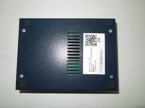
EXHIBIT B EXTERNAL PHOTOS Product ref: Wavenet NESO24-23 FCC ID: 2BC55NESO24-23

Internal Photos

EXHIBIT A INTERNAL PHOTOS Product ref: Wavenet NESO24-23 FCC ID: 2BC55NESO24-23

Parts List/Tune Up Info

Page 1 of 13 SPE-11-8-128-G Specification Part No. : GW.11.A153 Product Name : 2.4GHz 2.3dBi Terminal Mount Dipole Antenna Description : Connector Mount Terminal Antenna 90 Degree Hinged Connector Black TPE Housing Straight Length: 84mm Connector : RP-SMA(M) ROHS Compliant Page 2 of 13 SPE-11-8-128-G 1. Introduction The GW.11 2.4 GHz dipole RP-SMA terminal mount antenna is ideal for 2.4GHz wireless applications such as Bluetooth and Wireless LAN. At only 84mm in length omni- directional 2.3dBi gain across all bands ensures constant reception and transmission. The antenna structure is designed for robust handling and the housing is made with TPE giving superior environmental reliability and a quality finish. The antenna can be rotated 90 degrees on the base hinge for ease of placement. Many module manufacturers specify peak gain limits for any antennas that are to be connected to that module. Those peak gain limits are based on free-space conditions. In practice, the peak gain of an antenna tested in free-space can degrade by at least 1 or 2dBi when put inside a device. So ideally you should go for a slightly higher peak gain antenna than mentioned on the module specification to compensate for this effect, giving you better performance. Upon testing of any of our antennas with your device and a selection of appropriate layout, integration technique, or cable, Taoglas can make sure any of our antennas’ peak gain will be below the peak gain limits. Taoglas can then issue a specification and/or report for the selected antenna in your device that will clearly show it complying with the peak gain limits, so you can be assured you are meeting regulatory requirements for that module. For example, a module manufacturer may state that the antenna must have less than 2dBi peak gain, but you don’t need to select an embedded antenna that has a peak gain of less than 2dBi in free-space. This will give you a less optimized solution. It is better to go for a slightly higher free-space peak gain of 3dBi or more if available. Once that antenna gets integrated into your device, performance will degrade below this 2dBi peak gain due to the effects of GND plane, surrounding components, and device housing. If you want to be absolutely sure, contact Taoglas and we will test. Choosing a Taoglas antenna with a higher peak gain than what is specified by the module manufacturer and enlisting our help will ensure you are getting the best performance possible without exceeding the peak gain limits. It is better not to select an embedded antenna with very low free-space peak gain (<2dBi) directly, as this antenna would have worse performance in your device, and lead to compromised performance compared to using a Taoglas antenna. Connector mount is fully customizable. The GW.11 is also available in white. Page 3 of 13 SPE-11-8-128-G 2. Specification Table *The antenna was measured in free space Parameter GSM Band Communication System Bluetooth Wi-Fi ZigBee 2.4GHz ISM 2401-2480 2412-2462 2410-2480 2400-2483.5 Peak Gain (dBi)* 2.3 Average Gain (dB)* -0.88 Efficiency (%)* 80% Return Loss (dB)* - 10 dB Maximum Radiation Omni-directional Polarization Linear Vertical Power Handling 1W Impedance 50 Ω Mechanical Cable RG-178 Coaxial Cable Antenna Cover TPE Antenna Base PC & PBT Color Black Connector RP-SMA(M) Environmental Operation Temperature -40°C ~ + 85°C Storage Temperature -40°C ~ + 85°C Page 4 of 13 SPE-11-8-128-G 3. Antenna Characteristics 3.1 Return Loss 3.2 Peak Gain Page 5 of 13 SPE-11-8-128-G 3.3 Average Gain 3.4 Efficiency Page 6 of 13 SPE-11-8-128-G 4. Radiation Patterns Page 7 of 13 SPE-11-8-128-G -45 -35 -25 -15 -5 5 0 30 60 90 120 150 180 210 240 270 300 330 (dBi) 24 00 M Hz XY Plane XZ Plane YZ Plane X Y Z X Z Y Page 8 of 13 SPE-11-8-128-G 5. Drawing Page 9 of 13 SPE-11-8-128-G 6. Application Note 6.1 The GW.11 antenna measurment setup ( 40mm*60mm PCB board) Page 10 of 13 SPE-11-8-128-G 6.2 Return Loss when antenna setup on different conditions. Page 11 of 13 SPE-11-8-128-G 6.3 The GW.11 antenna measurment setup ( 40mmX100mm PCB board) 6.4 Return Loss when antenna setup on different conditions. Page 12 of 13 SPE-11-8-128-G 6.5 The GW.11 antenna measurment setup (90mmX150mm PCB board) 6.6 Return Loss when antenna setup on different conditions. Page 13 of 13 SPE-11-8-128-G Taoglas makes no warranties based on the accuracy or completeness of the contents of this document and reserves the right to make changes to specifications and product descriptions at any time without notice. Taoglas reserves all rights to this document and the information contained herein. Reproduction, use or disclosure to third parties without express permission is strictly prohibited. © Taoglas

RF Exposure Info

The results refer only and exclusively to the sample, product or material delivered for testing, and tested under conditions stipulated in this document. The equipment has been tested under conditions stipulated by standard(s) quoted in this document. This document will not be reproduced otherwise than in full. This is the first page of the document, which consists of 9 pages. LGAI Technological center, S.A. Inscrita en el Registro Mercantil de Barcelona, Tomo 35.803, Folio1, Hoja NºB-266.627 Inscripción 1ª. C.I.F. A-63207492 LGAI Technological Center, S.A. (APPLUS) Campus de la UAB. Ronda de la Font del Carme, s/n. 08193 Bellaterra (Barcelona) (Spain) T +34 93 567 20 00 / F +34 93 520 20 01 www.appluslaboratories.com File Number 23/36403869M1 TECHNICAL REPORT Human exposure Petitioner’s Reference: Servicios de Radio Wavenet Company Address: Pol. Ind. Requena, N79, 45214 Cedillo del Condado, Toledo Represented by: Julián Peral Alonso Equipment: Neso 2.4 Brand: Wavenet PMN: Neso 2.4 Sample #1: 2723/08A Applus Id: 17991-00006 Result: complies It has been tested and complies with the applicable standard. See test result summary section. Applicable Standard: EMC standard/s: FCC 47 CFR Part 2 Subpart J Section 2.1093 (October 2021) 1 KDB 447498 D01 - General RF Exposure Guidance 1 The latest modifications of the standard, published at the date of the tests reported in this document, have been considered. Dates and Test Site: Applus Barcelona, Bellaterra Equipment Reception Date September 25, 2023 Test Initial Date: October 9, 2023 Test Final Date: October 9, 2023 Modification Description: M1 This report replaces and supersedes the report 23/36403869 dated on October 31, 2023. Modification performed: Included explicit reference to PMN, HVIN and FVIN numbers. The antenna gains in table 2 and table 7 is modified according to the customer's specification. The EIRP value and Power Density at 20 cm is updated in table 7 and table 8. Pages 1, 3 and 9 are affected. In addition, general information updated. It is responsibility of the petitioner to replace the previous version with this one. Test Manager: Alejandro Sáez Date of issue: Bellaterra, December 12, 2023 EMC & Wireless Technical Manager Electrical and Electronics LGAI Technological Center S.A. File Number: 23/36403869M1 Page Number 2/9 Service Quality Assurance Applus+, guarantees that this work has been made in accordance with our Quality and Sustainability System, fulfilling the contractual conditions and legal norms. Within our improvement program we would be grateful if you would send us any commentary that you consider opportune, to the person in charge who signs this document, or to the Quality Manager of Applus+, in the following e-mail address: [email protected] 1 INDEX 1 INDEX ............................................................................................................................................... 2 2 GENERAL DESCRIPTION OF TEST ITEMS ........................................................................................ 3 2.1 EQUIPMENT DESCRIPTION ...................................................................................................... 3 2.2 TEST CONFIGURATION............................................................................................................. 4 2.2.1 Samples ............................................................................................................................... 5 2.2.2 Auxiliary Equipment .............................................................................................................. 6 2.2.3 DUT Modifications performed ................................................................................................. 7 2.3 DUT TEST MODES ..................................................................................................................... 7 2.4 CONTROL AND MONITORING .................................................................................................. 7 3 TEST RESULTS .................................................................................................................................. 8 3.1 HUMAN EXPOSURES STANDARDS ............................................................................................ 8 3.1.1 Test Parameters ................................................................................................................... 8 3.1.2 Test Results ......................................................................................................................... 9 File Number: 23/36403869M1 Page Number 3/9 Service Quality Assurance Applus+, guarantees that this work has been made in accordance with our Quality and Sustainability System, fulfilling the contractual conditions and legal norms. Within our improvement program we would be grateful if you would send us any commentary that you consider opportune, to the person in charge who signs this document, or to the Quality Manager of Applus+, in the following e-mail address: [email protected] 2 GENERAL DESCRIPTION OF TEST ITEMS 2.1 EQUIPMENT DESCRIPTION This information has been provided by the customer and it is not covered by the accreditation. LGAI does not assume any responsibility from it. Table 1: Equipment description Table 2: RF Features EQUIPMENT DESCRIPTION Description IEM/IFB TRANSMITTER EUT Version FVIN HVIN 2.3.1.0A 5.0A Power supply AC 1 PH + N 90 – 240 VAC 50-60 Hz Modulation GFSK Channel list Channel Freq [MHz] Channel Freq [MHz] Channel Freq [MHz] Channel Freq [MHz] 37 2402 9 2422 18 2442 28 2462 0 2404 10 2424 19 2444 29 2464 1 2406 38 2426 20 2446 30 2466 2 2408 11 2428 21 2448 31 2468 3 2410 12 2430 22 2450 32 2470 4 2412 13 2432 23 2452 33 2472 5 2414 14 2434 24 2454 34 2474 6 2416 15 2436 25 2456 35 2476 7 2418 16 2438 26 2458 36 2478 8 2420 17 2440 27 2460 39 2480 Equipment Type DTS RF FEATURES Radio chipset NORDIC 24L01 Brand Wavenet Module model NESO 2.4 Peak gain antenna 2.3 …

Text truncated - open the document above for the full version.

Test Report

The results refer only and exclusively to the sample, product or material delivered for testing, and tested under conditions stipulated in this document. The equipment has been tested under conditions stipulated by standard(s) quoted in this document. This document will not be reproduced otherwise than in full. This is the first page of the document, which consists of 78 pages. LGAI Technological center, S.A. Inscrita en el Registro Mercantil de Barcelona, Tomo 35.803, Folio1, Hoja NºB-266.627 Inscripción 1ª. C.I.F. A-63207492 LGAI Technological Center, S.A. (APPLUS) Campus de la UAB. Ronda de la Font del Carme, s/n. 08193 Bellaterra (Barcelona) (Spain) T +34 93 567 20 00 / F +34 93 520 20 01 www.appluslaboratories.com File Number 23/36403866M2 TEST REPORT Radiofrequency Petitioner’s Reference: Servicios de Radio Wavenet Company Address: Pol. Ind. Requena, N79, 45214 Cedillo del Condado, Toledo Represented by: Julián Peral Alonso Equipment: Neso 2.4 Brand: Wavenet PMN: Neso 2.4 Sample #1: 2723/08A Applus Id: 17991-00006 Result: complies It has been tested and complies with the applicable standard. See test result summary section. Applicable Standard: EMC standard/s: FCC 47 CFR Part 15 Subpart C (October 2021) 1 RSS-247 – Issue 2 (February 2017) 1 The latest modifications of the standard, published at the date of the tests reported in this document, have been considered. Dates and Test Site: Applus Barcelona, Bellaterra Equipment Reception Date September 25, 2023 Test Initial Date: October 3, 2023 Test Final Date: October 4, 2023 Modification Description: M1 This report replaces and supersedes the report 23/36403866 dated on October 31, 2023. Modifications performed: Included explicit reference to PMN, HVIN and FVIN numbers and summary of limits and measuring distance of section 4.7.3.1 updated due to an error in the test template. Pages 1, 5, 41 and 51 are affected. It is responsibility of the petitioner to replace the previous version with this one. Modification Description: M2 This report replaces and supersedes the report 23/36403866M1 dated on November 17, 2023. Modification performed: The antenna gains in table 2 and table 22 are modified according to the customer's specification. The EIRP value is updated in the Maximum Peak Conducted Output Power test in section 4.4.6. Pages 5 and 26 are affected. In addition, general information updated. It is responsibility of the petitioner to replace the previous version with this one. Test Manager: Alejandro Sáez Date of issue: Bellaterra, December 12, 2023 EMC & Wireless Technical Manager Electrical and Electronics LGAI Technological Center S.A. File Number: 23/36403866M2 Page Number 2/78 Service Quality Assurance Applus+, guarantees that this work has been made in accordance with our Quality and Sustainability System, fulfilling the contractual conditions and legal norms. Within our improvement program we would be grateful if you would send us any commentary that you consider opportune, to the person in charge who signs this document, or to the Quality Manager of Applus+, in the following e-mail address: [email protected] 1 TEST RESULTS SUMMARY Test Description Sample # DUT Test Modes Results Criteria Note ANTENNA REQUIEREMENTS (FCC Part 15.247 (d), RSS-247 5.5) #1 - PASS N/A OCCUPIED BANDWIDTH (99%) (FCC Part 15.247 (a), RSS-247 5.2) #1 Mode 1 PASS CN4 6 dB BANDWITDH (FCC Part 15.247 (a), RSS-247 5.2) #1 Mode 1 PASS CN4 MAXIMUM PEAK CONDUCTED OUTPUT POWER (FCC Part 15.247 (c), RSS-247 5.4) #1 Mode 1 PASS CN4 POWER SPECTRAL DENSITY (FCC Part 15.247 (b), RSS-247 5.4) #1 Mode 1 PASS CN3 BAND EDGE (FCC Part 15.247 (d), RSS-247 5.5) #1 Mode 1 PASS CN4 RADIOFREQUENCY RADIATED EMISSIONS (FCC Part 15.247 (d), RSS-247 5.5) #1 Mode 1 PASS CN3 The test results are shown in detail on the following pages. The criteria to give conformity in those cases where it is not implicit in the standard or specification will be, for EMC emissions tests, a non-simple binary decision rule will be followed with a safety zone equal to the value of the uncertainty (w = U). In this case, the upper limit of the value of the probability of false acceptance, according to ILAC G8, is 2.5 % and the criteria notes are: CN1: The measured results are above the upper limit, even considering the uncertainty interval. CN2: The measured results are above the specified limits, but within the uncertainty interval. It is therefore not possible to state compliance based on the 95% level of confidence. However, the results indicate that non-compliance is more probable than compliance. CN3: The measured results are below the specified limits, but within the uncertainty interval. It is therefore not possible to state compliance based on the 95% level of confidence. However, the results indicate that compliance is more probable than non-compliance. CN4: The measured results are within the limits, including the uncertainty interval. File Number: 23/36403866M2 Page Number 3/78 2 INDEX 1 TEST RESULTS SUMMARY ................................................................................................................ 2 2 INDEX ............................................................................................................................................... 3 3 GENERAL DESCRIPTION OF TEST ITEMS ........................................................................................ 5 3.1 EQUIPMENT DESCRIPTION ...................................................................................................... 5 3.2 TEST CONFIGURATION............................................................................................................. 6 3.2.1 Samples ............................................................................................................................... 7 3.2.2 Auxiliary Equipment .............................................................................................................. 8 3.2.3 DUT Modifications performed ...........…

Text truncated - open the document above for the full version.

Test Setup Photos

EXHIBIT C SETUP PHOTOS Product ref: Wavenet NESO24-23 FCC ID: 2BC55NESO24-23 Conducted Test Setup Radiated Test Setup

Contact Information

Applicant

JULIAN PERAL(MR)
[email protected]+34-925508791Fax: +34-92550792

Technical Contact

SERVICIOS DE RADIO WAVENET, S.L.Julian Peral Alonso
[email protected]0034 925508761

Poligono Industrial Requena · Cedillo Del Condado, Toledo · Spain

Non-Technical Contact

SERVICIOS DE RADIO WAVENET, S.L.Julian Peral Alonso
[email protected]0034 925508761

Test Firm

LGAI Technological Center, S.A.Javier Ema Lopez
[email protected]0034-935672000Fax: 0034-935672001

Technical Specifications

#Rule PartsFrequency RangePower Output
115C2.40 GHz - 2.48 GHz7.00 mW
Confidentiality
Long Term
Grant Notes
Output power listed is conducted