FCCID.CO- FCC ID Database
HomeCompaniesEquipment ClassesSearch

© 2026 FCC ID Database. All rights reserved.

AboutContactData sourced from FCC public records
  1. Home/
  2. TCL Co.,Ltd/
  3. 2BC9S-WHSR-S100

2BC9S-WHSR-S100Smart Reco

TCL Co.,Ltd
Smart Reco - FCC ID 2BC9S-WHSR-S100 - TCL Co.,Ltd
Click to zoom

Application Details

Equipment Class
DTS - Digital Transmission System
Date of Grant
Dec 11, 2023
Application Purpose
Original Equipment
Date of Application
Dec 11, 2023
Equipment Note
Smart Reco
Frequency Range
2412.00000000 - 2462.00000000
Company
TCL Co.,Ltd
Country
Japan

Documents & Files

Select a file to view

Users Manual

↗

Attestation Statements

↗
↗

Cover Letter(s)

↗
↗
↗
↗

External Photos

ID Label/Location Info

↗

Internal Photos

↗

RF Exposure Info

↗

Test Report

↗
↗
↗
↗

Test Setup Photos

↗

Document Text

Text extracted from the exhibit documents filed with the FCC. Open a document above to read the original.

Users Manual

Ver1.0.0 1 USER’S MANUAL WHSR-S100 Table of contents 2 01. Precautions 02. Prohibitions 03. Cautions for use 04. Product features 05. Standard items 06. Name and functions 07. How to power on/off 08. How to insert/remove memory card 09. Installation -Precautions during installation 10. Button function and voice guidance operations 11. LED operation -main body 12. LED operation -side camera 13. Product functions 14. Ultra-low power mode 15. How to set up a smartphone app 16. Firmware update 17. PC viewer installation 18. PC viewer overview 19. PC viewer function 20. PC viewer -full screen mode 21. PC viewer -digital zoom 22. PC viewer -driving record 23. PC viewer -file open 24. Folder structure in SD card 25. Video files 26. Product specifications 27. Frequently Asked Questions 28. Warranty 3 4 6 9 12 13 15 16 17 21 22 23 24 28 29 48 50 51 52 55 56 57 59 60 62 69 71 74 01. Precautions This product is a two-channel dashcam that records the left video, right video, and indoor audio when a vehicle accident or impact is detected. It records data to assist in analyzing the causes of roadside accidents. • SmartReco® is a registered trademark of Whitehouse Corporation. • All contents of this manual are protected by copyright law. • The product names and other brand names mentioned in this manual are the trademarks or registered trademarks of their respective companies. • We are not responsible for any failures or accidents that may occur as a result ofimproper use, installation, or modification. • To ensure safe driving, please refrain from using electronic devices while operating a vehicle. • The images shown in this manual may differ from the actual product. • Please read this manual before using the product to ensure proper and safe usage. ▎ This product is a vehicle safety driving assistance device. In the event of an accident, All responsibility lies with the user. Please use the product for its intended purpose. ▎ This manual may be subject to change without notice in order toimprove product functionality. 3 02. Prohibitions . Please do not operate while driving. It may cause accidents or injuries. Be sure to stop the vehicle in a safe place before operating or inserting the microSD card. . Do not disassemble, repair, or modify the product. Be sure to contact your nearest authorized dealer or seller for repairs or servicing. . If it gets wet, never dry it with a heat source such as a microwave oven or hair dryer, etc. It can cause an explosion, deformation, or malfunction. Do not touch with wet hands. It can cause a fire, electric shock, or malfunction. . Do not plug in or unplug the cord. Not only can it cause communication problems, but it can also lead to fires, electric shocks, or malfunctions due to disconnections or short circuits. · Do not insert any foreign objects into the device. It may cause malfunctions, fires, electric shocks, and other hazards. Please exercise extra caution and avoid approaching infants or young children. · Never install in a location that obstructs visibility while driving. It may cause accidents or injuries. · Never install in a location that will interfere with the airbag. If the airbag does not operate properly or activates unexpectedly, the product may malfunction, leading to accidents or injuries. · Do not use this product if it is broken or defective. If any malfunction or abnormality occurs, please immediately stop using the product and contact the nearest authorized dealer or seller. Continued use may result in an accident, fire, or electric shock. · Keep the microSD card out of reach of children. · Please ensure that this product is securely attached to prevent any separation or accidental dropping. If the attachment is weak, it may come loose or fall off while driving, potentially causing an accident or injury. Performance may also be affected by vibrations. · Please do not clean this product. Do not use chemicals such as benzene, thinner, or alcohol, etc. as they may cause an explosion or fire. When performing maintenance, first unplug the power cord from the main unit. Make sure that the power is turned off. Then, gently wipe the unit with a soft cloth that has been lightly dampened with water. Finally, dry the unit. 4 Warning · Avoid using the parking monitoring mode for extended periods, typically exceeding 24 hours. If you want to use it for an extended period of time, utilize the ultra-low power mode to operate and prevent draining the vehicle battery. If the vehicle is not used for an extended period of time, please remember to turn off the parking monitoring switch. Even if the power cutoff function is activated, starting the engine may still be difficult. After activating the power cutoff function, no video is being recorded. · Do not drop or expose this product to strong shocks. · Avoid leaving it in hot weather or locations with high temperatures or extreme cold for extended periods of time. If the temperature of the main body is outside the operating temperature range (-20°C~70°C), the main body functions will not operate properly. Also, if the main body is located between the sunshade and the windshield, it may become excessively hot and fail to function properly. Some car models have sun visors or sun shadesthat may obstruct the rear camera. In that case, it is advisable to avoid using sun visors or sun shadeswhile recording. If you do use them, make sure they do not obstruct your view. · Ensure that cables/cords are routed in a way that does not obstruct driving or getting on and off the vehicle. · This product cannot be used on vehicles driven on unpaved roads, such as off-road vehicles or competition vehicles. · Videos recorded with this product cannot be used without permission, except for personal use, due to regulations such as the Copyright Act and the Personal Information Protection Act. Depending on the method of usage, individual rights, such as privacy, may be violated. · This product is not designed to prevent accidents. …

Text truncated - open the document above for the full version.

Attestation Statements

Rev 1/26/2023 TCL Co.,Ltd 29-1 Wago-Kitakagaya, Togo-Cho, Aichi-Gun, Aichi-Ken, 470-0153 Japan Tel: +81-80-3626-9268 / Fax : +81-561-37-5332 Federal Communications Commission Authorization and Evaluation Division 7435 Oakland Mills Road Columbia, MD 21046 USA Date: December, 07, 2023 Ref: Attestation Statements Part 2.911(d)(7) Filing FCC ID: 2BC9S-WHSR-S100 Applicant FRN: 0034379883 YOUNGSIK KIM of TCL Co.,Ltd (“the applicant”) certifies that, as of the date of the filing of the application, FCC US AGENT, LLC. is our designated U.S. agent for service of process for the above referenced FCC ID. YOUNGSIK KIM of TCL Co.,Ltd accepts to maintain an agent for no less than one year after the grantee has terminated all marketing and importation or the conclusion of any Commission-related proceeding involving the equipment. FCC US AGENT, LLC. accepts, as of the date of the filing of the application, the obligation of the designated U.S. agent for service of process for the above referenced FCC ID. Designated U.S. Agent Information: Name: FCC US AGENT, LLC. U.S. Agent FRN: 0033402884 Address: 3722 Illinois Avenue, Saint Charles, IL, 60174, USA Contact Person: Tim Payne Tel.: 708-571-3148 Email: [email protected] Sincerely, TCL Co.,Ltd FCC US AGENT, LLC. YOUNGSIK KIM / Manager Tim Payne

Attestation Statements

TCL Co.,Ltd 29-1 Wago-Kitakagaya, Togo-Cho, Aichi-Gun, Aichi-Ken, 470-0153 Japan Tel: +81-80-3626-9268 / Fax : +81-561-37-5332 Federal Communications Commission Authorization and Evaluation Division 7435 Oakland Mills Road Columbia, MD 21046 USA Date: December 05, 2023 Ref: Attestation Statements Part 2.911(d)(5)(i) Filing FCC ID: 2BC9S-WHSR-S100 YOUNGSIK KIM of TCL Co.,Ltd certifies that the equipment for which authorization is sought is not “covered” equipment prohibited from receiving an equipment authorization pursuant to section 2.903 of the FCC rules. Sincerely, YOUNGSIK KIM / Manager TCL Co.,Ltd TCL Co.,Ltd 29-1 Wago-Kitakagaya, Togo-Cho, Aichi-Gun, Aichi-Ken, 470-0153 Japan Tel: +81-80-3626-9268 / Fax : +81-561-37-5332 Federal Communications Commission Authorization and Evaluation Division 7435 Oakland Mills Road Columbia, MD 21046 USA Date: December 05, 2023 Ref: Attestation Statements Part 2.911(d)(5)(ii) Filing FCC ID: 2BC9S-WHSR-S100 YOUNGSIK KIM of TCL Co.,Ltd certifies that, as of the date of the filing of the application, the applicant is not identified on the Covered List as as a specifically named entity or any of its subsidiaries or affiliates Sincerely, YOUNGSIK KIM / Manager TCL Co.,Ltd

Cover Letter(s)

TCL Co.,Ltd 29-1 Wago-Kitakagaya, Togo-Cho, Aichi-Gun, Aichi-Ken, 470-0153 Japan Tel: +81-80-3626-9268 / Fax : +81-561-37-5332 Federal Communications Commission Authorization and Evaluation Division 1435 Oakland Mills Road Columbia, MD 21046 Date: December 05, 2023 Regarding FCC Application (FCC ID: 2BC9S-WHSR-S100) We, TCL Co.,Ltd, declare that the device does not support channel 12 ~ 13 in 2.4 GHz band. The firmware setting is not accessible by end users and/or unauthorized 3rd parties. Signature: YOUNGSIK KIM / Manager TCL Co.,Ltd

Cover Letter(s)

Supplier's Declaration of Conformity 47 CFR § 2.1077 Compliance Information Product Description: Smart Reco Model/Brand Name: WHSR-S100 Variant Model: - FCC Rule Part(s): FCC Part 15 Subpart B Class B Part 15.107(b) & Part 15.109(b) Applicant Name: TCL Co.,Ltd Applicant Address: 29-1 Wa g o-Kitakagaya, Togo-Cho, Aichi-Gun, Aichi-Ken, 470-0153 Japan Manufacturer Name: MISO E&T CO., LTD. Manufacturer Address: #953, 142, Ls-ro, Dongan-gu, Anyang-si, Gyeonggi-do, Korea Smart Reco Model WHSR-S100 has been tested in accordance with the measurement procedures specified in FCC Part 15 Subpart B class B and has been shown to be complied with the electromagnetic emission limits specified in FCC Rule Part 15 Subpart B class B. A testing of the sample product has been valid for the sample tested based on the reference test report. Responsible Party – U.S. Contact Information Company Name: FCC US Agent, LLC Company Address: 3722 Illinois Avenue, Saint Charles, IL, 60174, USA Telephone or Internet contact information : 708‐571‐3148 / [email protected] Date of Issue: December 07, 2023 Signed by : YOUNGSIK, KIM. Signature: TCL Co.,Ltd Address : 29-1 Wago-Kitakagaya, Togo-Cho, Aichi-Gun, Aichi-Ken, 470-0153 Japan

Cover Letter(s)

TCL Co.,Ltd 29-1 Wago-Kitakagaya, Togo-Cho, Aichi-Gun, Aichi-Ken, 470-0153 Japan Tel: +81-80-3626-9268 / Fax : +81-561-37-5332 Date: December 05, 2023 Federal Communications Commission Authorization and Evaluation Division Confidentiality Request regarding application for certification of FCC ID : 2BC9S-WHSR-S100 Pursuant to Sections 0.457 and 0.459 of the Commission’s Rules, we hereby request confidential treatment of information accompanying this application as outlined below: PERMANENT Exhibit Type File Name Part List Part List.pdf Schematics Diagram(s) Schematic.pdf Operation description Operation description.pdf Block diagram Block diagram.pdf And the above materials contain trade secrets and proprietary information not customarily released to the public. The public disclosure of these materials may be harmful to the applicant and provide unjustified benefits to its competitors. The applicant understands that pursuant to Section 0.457 of the Rules, disclosure of this application and all accompanying documentation will not be made before the date of the Grant for this application. Sincerely, YOUNGSIK KIM / Manager TCL Co.,Ltd

Cover Letter(s)

TCL Co.,Ltd 29-1 Wago-Kitakagaya, Togo-Cho, Aichi-Gun, Aichi-Ken, 470-0153 Japan Tel: +81-80-3626-9268 / Fax : +81-561-37-5332 Date: December 05, 2023 Federal Communications Commission 7435 Oakland Mills Road Columbia MD 21046 FCC ID : 2BC9S-WHSR-S100 To whom it may concern: I, the undersigned, hereby authorize Young-Jin, Lee of KES Co., Ltd. and hereafter referred to as KES Co., Ltd., to act on our behalf in all manners relating to application for equipment authorization, including signing of all documents relating to these matters. Any and all acts carried out by Young-Jin, Lee of KES Co., Ltd. on our behalf shall have the same effect as acts of our own. I, the undersigned, hereby certify that we are not subject to a denial of federal benefits, that includes FCC benefits, pursuant to Section 5301 of the Anti-Drug Abuse Act of 1988, 21 U.S.C. 853(a). In authorizing KES Co., Ltd. as our agent, we still recognize that we are responsible to: a) comply with the relevant provisions of the certification program; b) make all necessary arrangements for the conduct of the evaluation, including provision for examining documentation and access to all areas, records (including internal audit reports) and personnel for the purposes of evaluation (e.g. testing, inspection, assessment, surveillance, reassessment) and resolution of complaints; c) make claims regarding certification only in respect of the scope for which certification has been granted; d) do not use our product certification in such a manner as to bring the Certification Division into disrepute and not make any statement regarding our product certification which the Certification Division may consider misleading or unauthorized; e) upon suspension or cancellation of certification, discontinue use of all advertising matter that contains any reference thereto and return any certification documents as required by the Certification Division; f) use certification only to indicate the products are certified as being in conformity with specified standards; g) endeavor to ensure that no certificate or report nor any part thereof is used in a misleading manner; TCL Co.,Ltd 29-1 Wago-Kitakagaya, Togo-Cho, Aichi-Gun, Aichi-Ken, 470-0153 Japan Tel: +81-80-3626-9268 / Fax : +81-561-37-5332 h) ensure that any reference to our product certification in communication media such as documents, brochures or advertising, complies with the requirements of the Certification Division; i) keep a record of all complaints made known to the us relating to the product’s compliance with requirements of the relevant standard and to make these records available to the Certification Division when requested; j) take appropriate action with respect to such complaints and any deficiencies found in products or services that affect compliance with the requirements for certification; k) document the actions taken. This authorization is valid until further written notice from the applicant. Sincerely Yours, YOUNGSIK KIM / Manager TCL Co.,Ltd REMARK: 1. This authorization letter will be sent along with your application when filing with the Certification Division. 2. Please follow the format and type it on company letterhead and send original to us. 3. Authorized signature must be in agreement with grantee code contact in FCC database.

ID Label/Location Info

FCC ID : 2BC9S-WHSR-S100 Page 1 of 1 Label photo The device is so small that it is not practicable to place the statement specified under 15.19 statement request, the information required by this paragraph shall be placed in a prominent location in the User’s Manual.

Internal Photos

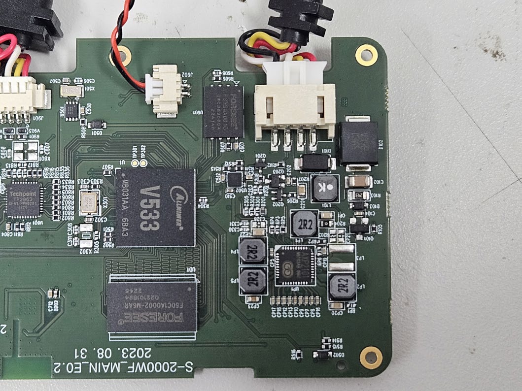
FCC ID : 2BC9S-WHSR-S100 Page 1 of 3 Internal photos Chip Antenna FCC ID : 2BC9S-WHSR-S100 Page 2 of 3 FCC ID : 2BC9S-WHSR-S100 Page 3 of 3 Blank

RF Exposure Info

FCC ID : 2BC9S-WHSR-S100 Page 1 of 1 RF exposure FCC ID : 2BC9S-WHSR-S100 According to FCC part 1.1310 : The criteria listed in the following table shall be used to evaluate the environment impact of human exposure to radio frequency (RF) radiation as specified in § 1.1307(b) Limits for Maximum Permissible Exposure (MPE) f= frequency in ㎒ Friis transmission formula: Pd = (Pout×G)/(4×pi×R 2 ) Where, Pd = power density in ㎽/㎠ Pout = output power to antenna in ㎽ G = gain of antenna in linear scale Pi = 3.1416 R = distance between observation point and center of the radiator in cm Pd the limit of MPE, 1 ㎽/㎠. If we know the maximum gain of the antenna and the total power input to the antenna, through the calculation, we will know the distance where the MPE limit is reached. Results Operation mode Frequency (㎒) Maximum Average output power (㏈m) Antenna gain (㏈i) Power density at 20 ㎝(㎽/㎠) Limit (㎽/㎠) 802.11b 1 Mbps (DC 12 V, DC 24 V) 2 412 ㎒ ~ 2 462 ㎒ 13.0 1.46 0.005 56 1 802.11g 6 Mbps (DC 12 V, DC 24 V) 2 412 ㎒ ~ 2 462 ㎒ 13.0 1.46 0.005 56 802.11n_HT20 MCS0 (DC 12 V, DC 24 V) 2 412 ㎒ ~ 2 462 ㎒ 13.0 1.46 0.005 56 Frequency range (㎒) Electric field strength(V/m) Magnetic field strength (A/m) Power density (㎽/㎠) Average time (A) Limits for Occupational / Control Exposures 300 – 1 500 -- -- f/300 6 1 500 - 100000 -- -- 5 6 (B) Limits for General Population / Uncontrol Exposures 300 – 1 500 -- -- f/1500 6 1 500 – 100 000 -- -- 1 30

Test Report

Application Bluetooth Zigbee WLAN (IEEE 802.11 b/g) ISM 2.4GHz Wireless Devices Features PIFA Structure Small Size (3.0*1.5*1.2mm 3 ) Easy Optimizing with external lumped matching components SMT Available under Pb-free Condition RoHS Compliant DATASHEET Document Datasheet Type Dielectric Chip Antenna Application 2.4GHz Part No. AMAN301512ST01 Revision 2.0 Notes The contents of this datasheet are subject to change without notice. Please confirm the specifications and delivery conditions when placing your order. AMOTECH AMOTECH Co., Ltd. Datasheet / Dielectric Chip Antenna / 2.4GHz AMAN301512ST01 (Rev 2.0) 2 Rev. No Date Title Contents Page 0 08.09.30 New published 1 09.03.24 Data Added Efficiency data 8 Changed carrier tape width (W16mm  W12mm) 12 1.1 09.04.07 Format Changed document format 1.2 14.08.06 Corrected the miswritten values 3 2 14.09.30 Data Changed Antenna Specification & Measured Result 3,5,6 Table of Content Revision History 1. Specifications 3 1.1 Electrical Specifications 3 1.2 Mechanical Specifications 3 1.3 Appearance and Material 3 2. PCB Design for Test 4 2.1 Evaluation Board Dimension 4 2.2 PCB Design Guide 4 3. Measurement Result 5 3.1 Typical Measurement Result (VSWR/RL, Smithchart) 5 3.2 Typical Measurement Result (Gain, Radiation Pattern) 6 4. Reliability 7 5. Soldering Reflow Profile 7 6. Packaging 8 6.1 Carrier Tape Dimension 8 6.2 Packaging Quantity 8 6.3 Packaging Label 8 Datasheet / Dielectric Chip Antenna / 2.4GHz AMAN301512ST01 (Rev 2.0) 3 No Item Spec. Remark 1 Frequency Range [GHz] 2.4 ~2.485 2 VSWR Max 3.0:1 3 Avg. Gain [dBi] typ. -1.4 4 Efficiency [%] typ. 71.7 5 Polarization Linear 6 Impedance [Ω] Nominal 50  The results are measured on the 50x50mm 2 evaluation board(EVB).  See Page 6. for more detail gain parameter No Item Spec. Remark 1 Dimensions (LxWxH) 3.0x1.5x1.2 mm 3 2 Unit Weight typ. 20 mg 3 Operating Temperature -35 ~ +85 °C 1.1 Electrical Specifications 1.2 Mechanical Specifications No Item Function Material ① Marking Feeding Index Ink ② Marking Week number Ink ③ Electrode Radiation Element Ag ④ Ceramic Body - Ceramic 1.3 Appearance & Material 1. Specifications ② ③ ① ④ [unit : mm] Datasheet / Dielectric Chip Antenna / 2.4GHz AMAN301512ST01 (Rev 2.0) 4 2.1 Evaluation Board Dimension 2.2 PCB Design Guide 2. PCB Design for Test ② ③ ① No Pin Assignment ① Feeding ② GND ③ GND Matching Component 50 Ohm Feeding Line [unit : mm]  Evaluation board size ~ 50x50  Fill Cut Area (GND Clearance) ~ 7.5x3.3 [PCB Solder Land] Datasheet / Dielectric Chip Antenna / 2.4GHz AMAN301512ST01 (Rev 2.0) 5 3.1 Typical Measurement Result (VSWR/RL, Smithchart) 3. Measurement Result  The results are measured on the 50x50mm 2 evaluation board(EVB). ② ③ ① No Matching Value ① 1.0 nH ② 4.7 nH ③ 1.2 pF Datasheet / Dielectric Chip Antenna / 2.4GHz AMAN301512ST01 (Rev 2.0) 6 [Eleviation1 plane @2.442GHz ] [Elevation2 plane @2.442GHz ] [Azimuth plane @2.442GHz ] [3D Radiation Pattern] x y z -y Azimuth E1 E2 Peak Gain (dBi) Avg. Gain (dBi) Total Avg. Gain (dBi) Efficiency (%) Elevation 1 0.77 -2.65 -1.44 71.73 Elevation 2 1.46 -1.06 Azimuth 0.97 -2.45 3.2 Typical Measurement Result (Gain, Radiation Pattern) Datasheet / Dielectric Chip Antenna / 2.4GHz AMAN301512ST01 (Rev 2.0) 7 No Item Test Condition Test Requirements 1 Adhesive Strength of Termination 1.Applied force on SMT chip till detached point from PCB. 1. No mechanical damage by applied force 2. Strength (F) > 3 kgf 2 Thermal Shock (Cycle) 1. Step 1 : -40 ± 3°C, 30 min Step 2 : +125 ± 3°C, 30 min 2. Number of cycle : 30 1. No visual damage 2. Within electric spec (VSWR) 3 High Temperature Resistance 1. Temperature : +125 ± 5°C 2. Time : 1000 ± 24 hrs 1. No visual damage 2. Within electric spec (VSWR) 4 Low Temperature Resistance 1. Temperature : -40 ± 5°C 2. Time : 1000 ± 24 hrs 1. No visual damage 2. Within electric spec (VSWR) 5 Humidity 1. Humidity : 85 % RH Temperature : +85 ± 3°C 2. Time : 1000 ± 24 hrs 1. No visual damage 2. Within electric spec (VSWR) F SMD PAD PCB 4. Reliability 5. Soldering Reflow Profile Datasheet / Dielectric Chip Antenna / 2.4GHz AMAN301512ST01 (Rev 2.0) 8 Item Spec. Item Spec. Item Spec. A0 1.80 ±0.10 P0 4.00 ±0.10 E 1.75 ±0.10 B0 3.30 ±0.10 P1 4.00 ±0.10 F 5.50 ±0.10 K0 1.35 ±0.10 P2 2.00 ±0.10 W 12.00 ±0.30 D0 1.55 ±0.05 - - t 0.30 ±0.05 Item Quantity Dimension Reel 2,500ea Φ7” * 12mm Inner Box 7,500 ea (3 reel) 185 * 185 * 68 (mm 3 ) Outer Box1 37,500 ea (5 Inner Box) 365 * 200 * 200 (mm 3 ) Outer Box2 105,000 ea (14 Inner Box) 390 * 390 * 280 (mm 3 ) 6.1 Carrier Tape Dimension 6.2 Packaging Quantity 6.3 Packaging Label 6. Packaging AMOTECH Co., Ltd. 5BL-1Lot, 617, Namchon-Dong, Namdong-Gu, Incheon, Korea Dielectric Chip Antenna P/N : AMAN301512ST01 Lot No : Quantity : 2,500 pcs Date : 2009/04/09 ▲ ▲

Test Report

Report No. : KES-RF-23T0159 Page72/86 KES-QP16-F01(00-23-01-01)KES Co., Ltd. The authenticity of the test report, contact [email protected] 3.5.Conducted spurious emissions & band edge Test setup EUTAttenuator Spectrum analyzer Test procedure Band edge ANSI C63.10-2013 - Section 11.11 1.Start and stop frequency were set such that the band edge would be placed in the center of the plot 2.Span was set large enough so as to capture all out of band emissions near the band edge 3.Set the RBW = 100㎑ 4.Set the VBW = [3 × RBW]. 5.Detector = Peak 6.Sweep time = auto 7.Trace mode = max hold 8.Allow trace to fully stabilize. Out of band emissions ANSI C63.10-2013 - Section 11.11 1.Start frequency was set to 30㎒and stop frequency was set to 25㎓for 2.4㎓frequencies and 40㎓for 5㎓frequencies 2.Set the RBW = 100㎑ 3.Set the VBW = [3 × RBW]. 4.Detector = Peak 5.Sweep time = auto 6.Trace mode = max hold 7.Allow trace to fully stabilize. Limit According to 15.247(d), in any 100㎑bandwidth outside the frequency band in which the spread spectrum or digitally modulated intentional radiator is operating, the radio frequency power that is produced by the intentional radiator shall be at least 20㏈below that in the 100㎑bandwidth within the band that contains the highest level of the desired power, based on either an RF conducted or a radiated measurement, provided the transmitter demonstrates compliance with the peak conducted power limits. If the transmitter complies with the conducted power limits based on the use of RMS averaging over a time interval , as permitted under paragraph(b)(3) of this section , the attenuation required under this paragraph shall be 30㏈ instead of 20㏈. Attenuation below the general limits specified in section 15.209(a) is not required. In addition, radiated emission which in the restricted band, as define in section 15.205(a), must also comply the radiated emission limits specified in section 15.209(a) (see section 15.205(c)) 시 점 확 인 필 정 부 시 점 확 인 센 터 진본 2023-12-08 09:48:28 KST Report No. : KES-RF-23T0159 Page73/86 KES-QP16-F01(00-23-01-01)KES Co., Ltd. The authenticity of the test report, contact [email protected] Test results 802.11b (1 Mbps)_DC 12 V 2 412㎒2 437㎒ Report No. : KES-RF-23T0159 Page74/86 KES-QP16-F01(00-23-01-01)KES Co., Ltd. The authenticity of the test report, contact [email protected] 802.11b (1 Mbps)_DC 12 V 2 462㎒ Blank Report No. : KES-RF-23T0159 Page75/86 KES-QP16-F01(00-23-01-01)KES Co., Ltd. The authenticity of the test report, contact [email protected] 802.11b (1 Mbps)_DC 24 V 2 412㎒2 437㎒ Report No. : KES-RF-23T0159 Page76/86 KES-QP16-F01(00-23-01-01)KES Co., Ltd. The authenticity of the test report, contact [email protected] 802.11b (1 Mbps)_DC 24 V 2 462㎒ Blank Report No. : KES-RF-23T0159 Page77/86 KES-QP16-F01(00-23-01-01)KES Co., Ltd. The authenticity of the test report, contact [email protected] 802.11g (6 Mbps)_DC 12 V 2 412㎒2 437㎒ Report No. : KES-RF-23T0159 Page78/86 KES-QP16-F01(00-23-01-01)KES Co., Ltd. The authenticity of the test report, contact [email protected] 802.11g (6 Mbps)_DC 12 V 2 462㎒ Blank Report No. : KES-RF-23T0159 Page79/86 KES-QP16-F01(00-23-01-01)KES Co., Ltd. The authenticity of the test report, contact [email protected] 802.11g (6 Mbps)_DC 24 V 2 412㎒2 437㎒ Report No. : KES-RF-23T0159 Page80/86 KES-QP16-F01(00-23-01-01)KES Co., Ltd. The authenticity of the test report, contact [email protected] 802.11g (6 Mbps)_DC 24 V 2 462㎒ Blank Report No. : KES-RF-23T0159 Page81/86 KES-QP16-F01(00-23-01-01)KES Co., Ltd. The authenticity of the test report, contact [email protected] 802.11n_HT20 (MCS0)_DC 12 V 2 412㎒2 437㎒ Report No. : KES-RF-23T0159 Page82/86 KES-QP16-F01(00-23-01-01)KES Co., Ltd. The authenticity of the test report, contact [email protected] 802.11n_HT20 (MCS0)_DC 12 V 2 462㎒ Blank Report No. : KES-RF-23T0159 Page83/86 KES-QP16-F01(00-23-01-01)KES Co., Ltd. The authenticity of the test report, contact [email protected] 802.11n_HT20 (MCS0)_DC 24 V 2 412㎒2 437㎒ Report No. : KES-RF-23T0159 Page84/86 KES-QP16-F01(00-23-01-01)KES Co., Ltd. The authenticity of the test report, contact [email protected] 802.11n_HT20 (MCS0)_DC 24 V 2 462㎒ Blank Report No. : KES-RF-23T0159 Page85/86 KES-QP16-F01(00-23-01-01)KES Co., Ltd. The authenticity of the test report, contact [email protected] 3.6.Antenna Requirement According to 15.207(a), An intentional radiator shall be designed to ensure that no antenna other than that furnished by the responsible party shall be used with the device. The use of a permanently attached antenna or of an antenna that uses a unique coupling to the intentional radiator shall be considered sufficient to comply with the provisions of this Section. The manufacturer may design the unit so that a broken antenna can be replaced by the user, but the use of a standard antenna jack or electrical connector is prohibited. This requirement does not apply to carrier current devices or to devices operated under the provisions of Sections 15.211, 15.213, 15.217, 15.219, or 15.221. Further, this requirement does not apply to intentional radiators that must be professionally installed, such as perimeter protection systems and some field disturbance sensors, or to other intentional radiators which, in accordance with Section 15.31(d), must be measured at the installation site. However, the installer shall be responsible for ensuring that the proper antenna is employed so that the limits in this Part are not exceeded. Report No. : KES-RF-23T0159 Page86/86 KES-QP16-F01(00-23-01-01)KES Co., Ltd. The authenticity of the test report, contact [email protected] Appendix A. Measurement equipment EquipmentManufacturerModelSerial No. Calibration interval Calibration due. Spectrum analyzerR&SFSV30441012721 year2024.03.16 Spectrum analyzerR&SFSV40-N1021941 year2024.08.08 SIGNAL GENERATORKEYSIGHTN5182BMY591001151 year2024.04.19 SIGNAL GENERATORAnritsu68369B0021181 year2024.05.12 Power MeterAnritsuML2495A20100011 year2024.04.19 Pulse Power SensorAnritsuMA2411B19111111 year2024.04.18 AttenuatorMini-Circuits…

Text truncated - open the document above for the full version.

Test Report

Report No. : KES-RF-23T0159 Page28/86 KES-QP16-F01(00-23-01-01)KES Co., Ltd. The authenticity of the test report, contact [email protected] Duty cycle Regarding to KDB 558074 D01_v05 r02, 6. Measurements of duty cycle and transmission duration shall be performed using one of the following techniques: a) A diode detector and an oscilloscope that together have sufficiently short response time to permit accurate measurements of the on- and off-times of the transmitted signal. b) The zero-span mode on a spectrum analyzer or EMI receiver if the response time and spacing between bins on the sweep are sufficient to permit accurate measurements of the on- and off-times of the transmitted signal. Mode T on time (㎳) Period (㎳) Duty cycle (Linear) Duty cycle (%) Duty cycle correction factor (㏈) 802.11b DC 12 V 4.174.380.9595.210.22 802.11b DC 24 V 4.174.380.9595.210.22 802.11g DC 12 V 0.710.970.7373.201.37 802.11g DC 24 V 0.710.970.7373.201.37 802.11n_HT20 DC 12 V 0.680.920.7473.911.31 802.11n_HT20 DC 24 V 0.680.920.7473.911.31 Duty cycle (Linear) = T on time/Period DCF(Duty cycle correction factor (㏈)) = 10log(1/duty cycle) 802.11b (1 Mbps)_ DC 12 V802.11b (1 Mbps)_ DC 24 V 시 점 확 인 필 정 부 시 점 확 인 센 터 진본 2023-12-08 09:47:54 KST Report No. : KES-RF-23T0159 Page29/86 KES-QP16-F01(00-23-01-01)KES Co., Ltd. The authenticity of the test report, contact [email protected] 802.11g (6 Mbps)_ DC 12 V802.11g (6 Mbps)_ DC 24 V 802.11n_HT20 (MCS0)_ DC 12 V802.11n_HT20 (MCS0)_ DC 24 V Report No. : KES-RF-23T0159 Page30/86 KES-QP16-F01(00-23-01-01)KES Co., Ltd. The authenticity of the test report, contact [email protected] Test results (Below 30㎒) Mode:802.11g (6 Mbps)_12 V Distance of measurement:3 meter Channel:1 (Worst case) Parallel Note. 1. No spurious emission were detected under 30㎒.. Report No. : KES-RF-23T0159 Page31/86 KES-QP16-F01(00-23-01-01)KES Co., Ltd. The authenticity of the test report, contact [email protected] Mode:802.11g (6 Mbps)_24 V Distance of measurement:3 meter Channel:6 (Worst case) Parallel Note. 1. No spurious emission were detected under 30㎒. Report No. : KES-RF-23T0159 Page32/86 KES-QP16-F01(00-23-01-01)KES Co., Ltd. The authenticity of the test report, contact [email protected] Test results (Below 1 000㎒) Mode:802.11g (6 Mbps)_12 V Distance of measurement:3 meter Channel:1 (Worst case) Horizontal // Vertical Report No. : KES-RF-23T0159 Page33/86 KES-QP16-F01(00-23-01-01)KES Co., Ltd. The authenticity of the test report, contact [email protected] Mode:802.11g (6 Mbps)_24 V Distance of measurement:3 meter Channel:6 (Worst case) Horizontal // Vertical Report No. : KES-RF-23T0159 Page34/86…

Text truncated - open the document above for the full version.

Contact Information

Applicant

YOUNGSIK KIM
[email protected]81-561-67-5511Fax: 81-561-37-5332

Test Firm

KES Co., LtdInsung Ryu
[email protected]82-31-425-6200Fax: 82-31-424-0450

Technical Specifications

#Rule PartsFrequency RangePower Output
115C2.41 GHz - 2.46 GHz45.39 mW
Confidentiality
Long Term
Grant Notes
Output Power listed is the maximum conducted output power. The antenna(s) used for this transmitter must be installed and operated so as to provide a separation distance of at least 20 cm from all persons and must not be co-located or operating in conjunction with any other antenna or transmitter, except in accordance with FCC multi-transmitter product procedures, or as evaluated in this filing. End-users must be informed of operating requirements for satisfying RF exposure compliance. This device supports 20 MHz bandwidth modes.