2BCD9-YET3604A-4Kwireless remote control
Synergy Light LLC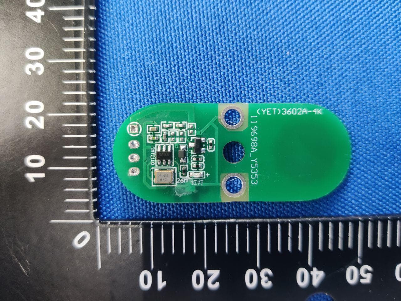
Click to zoom
Application Details
- Equipment Class
- DSC - Part 15 Security/Remote Control Transmitter
- Date of Grant
- Sep 25, 2023
- Application Purpose
- Original Equipment
- Date of Application
- Sep 25, 2023
- Equipment Note
- wireless remote control
- Frequency Range
- 315.00000000 - 315.00000000
- Company
- Synergy Light LLC
- Country
- United States
Documents & Files
Document Text
Text extracted from the exhibit documents filed with the FCC. Open a document above to read the original.
Users Manual
深圳市遥尔泰科技发展有限公司 SHENZHEN YAOERTAI TECHNOLOGY DEVELOPMENT CO.,LTD http://www.szyet.com0755-89509951 89509953 1 (YET)SC3604A-4K Manual for remote control 1、Output mode of remote control The remote control is powered by a CR1233V battery and encoded by the EV1527 chip. After the user presses the key, the K1 K2 chip recognizes the key and sends out the corresponding coded modulation signal, the 315M wireless signal is produced by OOK modulation, and then radiated by RF integrated chip CMT2110 and 3DBI gain antenna. Wiring as shown in Figure A: 2、Main technical indicators 1、 Operating voltage:DC3V 2、Static working current:≤0UA 3、 Operating temperature:-20°C - +80°C4、Firing Range:More than 60 meters 5、 Transmission frequency:315MHz 6、Press the button outside the remote control:Two buttons 3、Wiring diagram Figure A Add ANT DC +3V GND 7 . K1 and K2 are two coding buttons, and only when these two buttons are pressed will the remote control emit an RF signal; 8. Product Usage: Electronic products mainly used for wireless remote control, such as cars, access control, etc 深圳市遥尔泰科技发展有限公司 SHENZHEN YAOERTAI TECHNOLOGY DEVELOPMENT CO.,LTD http://www.szyet.com0755-89509951 89509953 2 Figure B FCC Warning: This equipment has been tested and found to comply with the limits for a Class B digital device, pursuant to part 15 of the FCC Rules. These limits are designed to provide reasonable protection against harmful interference in a residential installation. This equipment generates, uses and can radiate radio frequency energy and, if not installed and used in accordance with the instructions, may cause harmful interference to radio communications. However, there is no guarantee that interference will not occur in a particular installation. If this equipment does cause harmful interference to radio or television reception, which can be determined by turning the equipment off and o n, the user is encouraged to try to correct the interference by one or more of the following measures: • Reorient or relocate the receiving antenna. •Increase the separation between the equipment and receiver. •Connect the equipment into an outlet on a circuit different from that to which the receiver is connected. •Consult the dealer or an experienced radio/TV technician for help. Caution: Any changes or modifications to this device not explicitly approved by manufacturer could void your authority to operate this equipment. This device complies with part 15 of the FCC Rules. Operation is subject to the following two conditions: (1) This device may not cause harmful interference, and (2) this device must accept any interference received, including interference that may cause undesired operation. The device has been evaluated to meet general RF exposure requirement. The device can be used in portable exposure condition without restriction.
Attestation Statements
Rev 1/26/2023 Synergy Light LLC Federal Communications Commission Authorization and Evaluation Division 7435 Oakland Mills Road Columbia, MD 21046 USA Date: 9/15/2023 Ref: Attestation Statements Part 2.911(d)(5)(i) Filing FCC ID: 2BCD9-YET3604A-4K [Synergy Light LLC] certifies that the equipment for which authorization is sought is not “covered” equipment prohibited from receiving an equipment authorization pursuant to section 2.903 of the FCC rules. Sincerely, Signed: Printed name: Christopher Howell Title: Manager Company Name: Synergy Light LLC Rev 1/26/2023 Synergy Light LLC Federal Communications Commission Authorization and Evaluation Division 7435 Oakland Mills Road Columbia, MD 21046 USA Date: 9/15/2023 Ref: Attestation Statements Part 2.911(d)(5)(ii) Filing FCC ID: 2BCD9-YET3604A-4K [Synergy Light LLC] certifies that, as of the date of the filing of the application, the applicant is not identified on the Covered List (as a specifically name entity or any of its subsidiaries or affiliates) as an entity producing “covered” equipment. Sincerely, Signed: Printed name: Christopher Howell Title: Manager Company Name: Synergy Light LLC
Attestation Statements
Synergy Light LLC * the applicant must designate a contact located in the United States for purposes of acting as the applicant’s agent for service of process, regardless of whether the applicant is a domestic or foreign entity. An applicant located in the United States may designate itself as the agent for service of process. U.S. Agent Designation for Service of Process - Certification Attestation Letter 9/15/2023 ATTN.: Reviewing Engineer FCC ID: 2BCD9-YET3604A-4K Per section 2.911(d)(7) of the FCC rules, Synergy Light LLC (“the applicant”) certifies that the equipment for which authorization is sought is designated to the following U.S. agent* for service of process: Company Name: Synergy Light LLC Physical U.S. Company Address: 13328 Forest Park Drive Grand Haven Michigan 49417 Agent contact name/Title : Christopher Howell / Manager Agent Email Address: [email protected] Tel No.: +1616 268 9011 FRN No.: 0034095208 The above contact person accepts the obligation for service of process. The applicant accepts to maintain an agent for no less than one year after the grantee has terminated all marketing and importation or the conclusion of any Commission-related proceeding involving the equipment. Applicant Signed: Signed: Printed name: Christopher Howell Title: Manager Company Name: Synergy Light LLC Date: 9/15/2023 Agent Signed (if different to Applicant): Signed: Printed name: Christopher Howell Title: Manager Company Name: Synergy Light LLC Date: 9/15/2023
Cover Letter(s)
Synergy Light LLC 2023-09-15 Attn: Director of Certification Authority to Act as Agent On our behalf, I appoint Shenzhen Alpha Product Testing Co., Ltd. Address: Building i, No.2, Lixin Road, Fuyong Street, Bao’an District, 518103, Shenzhen, Guangdong, China Person: Mark Zhu (Name: Shenzhen Alpha Product Testing Co., Ltd. and address: Building i, No.2, Lixin Road, Fuyong Street, Bao’an District, 518103, Shenzhen, Guangdong, China). to act as our agent in the preparation of this application for equipment certification. I certify that submitted documents properly describe the device or system for which equipment certification is sought. I also certify that each unit manufactured, imported or marketed, as defined in the Federal Communications Commission’s regulations will have affixed to it a label identical to that submitted for approval with this application. For instances where our authorized agent signs the application for certification on our behalf, I acknowledge that all responsibility for complying with the terms and conditions for certification, as specified by TMICO still resides with Synergy Light LLC Address: 13328 Forest Park Drive Grand Haven Michigan 49417 (applicant name and address). Signature: Name Christopher Howell Position Manager Company Name Synergy Light LLC Address 13328 Forest Park Drive Grand Haven Michigan 49417 Tel +1616 268 9011 Fax +1616 414 5172 Email [email protected]
Cover Letter(s)
Synergy Light LLC Office of Engineering Technology Federal Communications Commission 7435 Oakland Mills Road Columbia, MD 21046 Date: September 15, 2023 Subject; Request for Long Term Confidentiality FCC ID: 2BCD9-YET3604A-4K To Whom It May Concern, Pursuant to the provisions of the Commission’s rules Title 47 Sections §0.457 and §0.459, we are requesting the Commission to withhold the following attachment(s) as confidential documents from public disclosure indefinitely. These documents contain detailed system and equipment descriptions and are considered as proprietary information in operation of the equipment. The public disclosure of these documents might be harmful to our company and would give competitors an unfair advantage in the market. Schematic Diagram Block Diagram Operational Description Tune up It is our understanding that all measurement test reports, FCC ID label format and correspondence during the certification review process cannot be granted as confidential documents and this information will be available for public review once the grant of equipment authorization is issued. Sincerely, Signature: September 15, 2023 Name Christopher Howell Position Manager Company Name Synergy Light LLC Address 13328 Forest Park Drive Grand Haven Michigan 49417 Tel +1616 268 9011 Fax +1616 414 5172 Email [email protected]
External Photos
FCC ID: 2BCD9-YET3604A-4K
ID Label/Location Info
FCC ID: 2BCD9-YET3604A-4K
Internal Photos
FCC ID: 2BCD9-YET3604A-4K
RF Exposure Info
FCC ID: 2BCD9-YET3604A-4K RF Exposure evaluation According to 447498 D04 Interim General RF Exposure Guidance v01 1-mW Test Exemption A single RF source is exempt RF device (from the requirement to show data demonstrating compliance to RF exposure limits, as previously mentioned) if the available maximum time-averaged power is no more than 1 mW, regardless of separation distance. This exemption applies to all operating configurations and exposure conditions, for the frequency range 100 kHz to 100 GHz, regardless of fixed, mobile, or portable device exposure conditions. This is a standalone exemption, and it cannot be applied in conjunction with any other test exemption. 1-mW Test Exemption for Multiple Sources The 1-mW exemption intended for single transmitters may be also applied to simultaneous transmission conditions, within the same host device, according one of the following criteria: a) When maximum available power each individual transmitting antenna within the same time averaging period is ≤ 1 mW, and the nearest parts of the antenna structures of the simultaneously operating transmitters are separated by at least 2 cm. b) When the aggregate maximum available power of all transmitting antennas is ≤ 1 mW in the same time-averaging period. This exemption may not be combined with any other exemption. SAR-Based Exemption This exemption is applicable to the frequency range between 300 MHz and 6 GHz, with test separation distances between 0.5 cm and 40 cm, and for all RF sources in fixed, mobile, and portable device exposure conditions. Accordingly, a RF source is considered an RF exempt device if its available maximum time-averaged (matched conducted) power or its effective radiated power (ERP), whichever is greater, are below a specified threshold. This exemption threshold was derived based on general population 1-g SAR requirements. This method shall only be used at separation distances from 0.5 cm to 40 cm and at frequencies from 0.3 GHz to 6 GHz (inclusive). Pth is given by follow Formulas “f” is in GHz, “d” is the separation distance (cm) FCC ID: 2BCD9-YET3604A-4K Simultaneous Transmission with SAR-based Exemptions For these cases, a device with multiple RF sources transmitting simultaneously will be considered an RF exempt device if the condition of following Formula is satisfied. (1-mW Test Exemption) As this equipment: EIRP = Pt * Gt = (E*d) 2 /30 So Pt=(E*d) 2 /(30*Gt) where: Pt = transmitter output power in watts, Gt = numeric gain of the transmitting antenna (unit-less), E = electric field strength in V/m, --- 10 ((dBuV/m)/20) /10 6 d = measurement distance in meters (m)---3m Field strength: E=68.7 dBuV/m @3m Ant gain 3 dBi; so Ant numeric gain Gt=2.00 So Pt={[10 (68.7/20) /10 6 x3] 2 /(30*2.00) }x1000 mW =0.004448 mW<1mW Then the SAR test is exempted.
Test Report
ALPHA's reports is using a digital certificate that is trusted on Adobe's official server. If there is no digital certificate or the digital certificate shows damaged in your report. Please do not accept the report. E-mail: [email protected] Tel: 4008-3008-95 Website: http://www.a-lab.cn FCC TEST REPORT FCC ID: 2BCD9-YET3604A-4K On Behalf of Synergy Light LLC wireless remote control Model No.: YET3604A-4K(S29) Prepared for : Synergy Light LLC Address : 13328 Forest Park Drive Grand Haven Michigan 49417 Prepared By : Shenzhen Alpha Product Testing Co., Ltd. Address : Building i, No.2, Lixin Road, Fuyong Street, Bao’an District, 518103, Shenzhen, Guangdong, China Report Number : A2307069-C01-R01 Date of Receipt : August 2, 2023 Date of Test : August 2, 2023 - September 11, 2023 Date of Report : September 12, 2023 Version Number : V0 Page 2 of 27 Report No.: A2307069-C01-R01 Contents 1. General Information ..........................................................................................................5 1.1. Description of Device (EUT) ............................................................................................ 5 1.2. Accessories of Device (EUT) .......................................................................................... 6 1.3. Tested Supporting System Details .................................................................................. 6 1.4. Test Facility ...................................................................................................................... 6 2. Summary of Test ...............................................................................................................7 2.1. Summary of Test Result .................................................................................................. 7 2.2. Block Diagram ................................................................................................................. 7 2.3. Test Mode ........................................................................................................................ 8 2.4. Test Conditions ................................................................................................................ 8 2.5. Measurement Uncertainty (95% confidence levels, k=2) ................................................ 8 2.6. Test Equipment ................................................................................................................ 9 3. Radiation Emission ........................................................................................................ 10 3.1. Radiation Emission Limits(15.209&231) ....................................................................... 10 3.2. Test Setup ...................................................................................................................... 10 3.3. Test Procedure .............................................................................................................. 11 3.4. Test Equipment Setting For emission test. .................................................................... 12 3.5. Test Condition ................................................................................................................ 12 3.6. Test Result ..................................................................................................................... 12 4. Power Line Conducted Emission ................................................................................. 18 4.1. Conducted Emission Limits (15.209) ............................................................................. 18 4.2. Test Setup ...................................................................................................................... 18 4.3. Test Procedure .............................................................................................................. 18 4.4. Test Results ................................................................................................................... 19 5. Occupied bandwidth ...................................................................................................... 20 5.1. Test Limit ....................................................................................................................... 20 5.2. Method of Measurement................................................................................................ 20 5.3. Test Setup ...................................................................................................................... 20 5.4. Test Results ................................................................................................................... 20 6. Transmission Time ........................................................................................................ 22 6.1. Test Limit ....................................................................................................................... 22 6.2. Method of Measurement................................................................................................ 22 6.3. Test Setup ...................................................................................................................... 22 6.4. Test Results ................................................................................................................... 22 7. Antenna Requirement .................................................................................................... 24 7.1. Standard Requirement ................................................................................................... 24 7.2. Antenna Connected Construction ................................................................................. 24 7.3. Result............................................................................................................................. 24 8. Test Setup Photo ........................................................................................................... 25…
Text truncated - open the document above for the full version.
Test Setup Photos
FCC ID: 2BCD9-YET3604A-4K FCC ID: 2BCD9-YET3604A-4K FCC ID: 2BCD9-YET3604A-4K Conducted Emission
Contact Information
Applicant
Christopher Howell(Manager)
Test Firm
Shenzhen Alpha Product Testing Co., LTD.Real Yak
[email protected]+86 755 29766001
Technical Specifications
| # | Rule Parts | Frequency Range | Power Output |
|---|---|---|---|
| 1 | 15.231 | 315 MHz - 315 MHz | - |