2BCGGXM1Dry Fire System
Blue Ops LTD.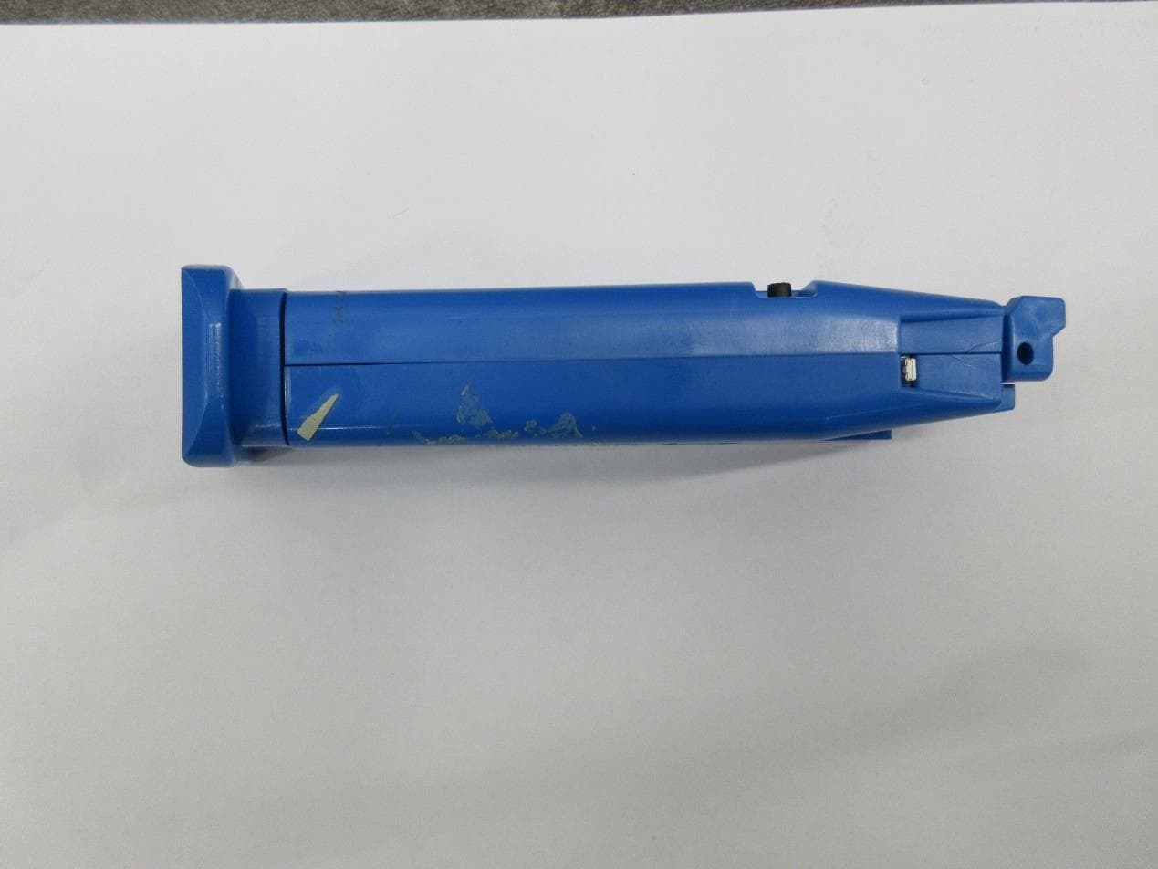
Click to zoom
Application Details
- Equipment Class
- DTS - Digital Transmission System
- Date of Grant
- Oct 30, 2023
- Application Purpose
- Original Equipment
- Date of Application
- Oct 30, 2023
- Equipment Note
- Dry Fire System
- Frequency Range
- 2402.00000000 - 2440.00000000
- Company
- Blue Ops LTD.
- Country
- Israel
Documents & Files
Document Text
Text extracted from the exhibit documents filed with the FCC. Open a document above to read the original.
Users Manual
BlueOpsBasicPackforGLOCK GeneralProductDescription: TheEUTisanindoorelectronicconsumerdeviceusedfordryfiretrainingathomeoratashootingrange. ItcontainsaBLEtransceiverforcommunicatingwithasmartphoneapplication.Unitisshapedintheform ofagunmagazineandisenteredintothegunforthetrainingpurpose.Whentheuserpullsthetrigger, theunitoperatesanexternallaserpointer.Unitispoweredbyarechargeable800mAhLiPObatteryandit cannotoperatewhilebeingcharged. ExternalbatterychargerisnotpartofEUT Intro: ThankyouforpurchasingtheBasicPackforGLOCKbyBlueOps.Weareconfidentthatyouwillenjoy usingthiscutting-edgetechnologyforyourtrainingneeds.Pleasereadthisusermanualcarefullyto ensuresafeandproperusageoftheproduct. PleaseensurethatyoufamiliarizeyourselfwiththeSafetyGuidelinesandUsageInstructionsprovidedin thismanualbeforeusingthexMAGandxLSRunits. What'sintheBox: ●2xMAGSmartMagazineunits ●1xLSRLaserCartridge ●USB-Cchargingcable ●3LR626batteries ●LaserExtractionTool ●2interchangeablebasepads SafetyGuidelines ●BlueOpsBasicPackforGLOCKwasbuiltwithtotalsafetyinmind.Nevertheless,please makesurethatyouclearyourweaponbeforestartinganydry-firepracticesession.Never assumethatyourfirearmisclear-alwaysdoublecheck! ●KeepxMAGandxLSRunitsawayfromliquids,includingwaterandoils.Exposuretoliquidsmay damagetheelectroniccomponentsandcompromisethefunctionalityoftheproduct. ●NeverattempttochargexMAGifitisnotcompletelydry.Moisturecancauseelectricalshort circuitsanddamagethedevice. ●UseonlytheincludedchargingcableforchargingxMAG.Theuseofunauthorizedcharging cablescanleadtomalfunctionordamagetotheproduct. ●Useonlybatteriesapprovedbythemanufacturer. ●OperatingTemperature:0°Cto40°C(32°Fto104°F) ●FCCID:2BCGGXM1 ○ThisdevicecomplieswithFCCRulesPart15:Operationissubjecttotwoconditions:(1) Thisdevicemaynotcauseharmfulinterference,and(2)thisdevicemustacceptany interferencethatmaybereceivedorthatmaycauseundesiredoperation. ○Warning:changesormodificationsnotexpresslyapprovedbythepartyresponsiblefor compliancecouldvoidtheuser'sauthoritytooperatetheequipment. ●Note:ThisequipmenthasbeentestedandfoundtocomplywiththelimitsforaClassBdigital device,pursuanttopart15oftheFCCRules.Theselimitsaredesignedtoprovidereasonable protectionagainstharmfulinterferenceinaresidentialinstallation.Thisequipmentgenerates, usesandcanradiateradiofrequencyenergyand,ifnotinstalledandusedinaccordancewiththe instructions,maycauseharmfulinterferencetoradiocommunications.However,thereisno guaranteethatinterferencewillnotoccurinaparticularinstallation.Ifthisequipmentdoescause harmfulinterferencetoradioortelevisionreception,whichcanbedeterminedbyturningthe equipmentoffandon,theuserisencouragedtotrytocorrecttheinterferencebyoneormoreof thefollowingmeasures: ○Reorientorrelocatethereceivingantenna. ○Increasetheseparationbetweentheequipmentandreceiver. ○Connecttheequipmentintoanoutletonacircuitdifferentfromthattowhichthereceiver isconnected. ○Consultthedealeroranexperiencedradio/TVtechnicianforhelp. GettingStarted: 1.ImportantNote:xMAGisacutting-edgepieceoftechnologythatincludeselectroniccomponents. AtanytimeduringtheusageofxMAG,makesuretoavoidtouchingtheIndicatorwhiteLEDat theupperfrontendofxMAG(refertoFigure1intheusermanual). 2.ThexMAGunitispartlychargedoutofthebox.However,itisrecommendedtofullychargeit beforetheinitialuse. 3.Charging a.ConnectoneendoftheincludedUSB-Cchargingcabletothechargingportlocatedon thebackofthexMAGunit. b.ConnecttheotherendoftheUSB-Cchargingcabletoapowersource,suchasaUSB portonyourcomputeroracompatibleUSBwalladapter. c.Whilecharging,theIndicatorwhiteLEDwillblinkrapidlyindicatingthatxMAGis charging.Oncefullycharged,theLEDwillturnoff. d.DisconnectthechargingcablefromxMAGandthepowersourceonceitisfullycharged. 4.UnscrewtherearendofthexLSRLaserCartridge(refertoFigure2intheusermanual). 5.Insertthe3includedLR626batteriesintothecartridge,ensuringtheminus(-)sideofeach batteryisfacingup. 6.TurnONbothxMAGSmartMagazinesbypressingonceontheblackswitchlocatedontheright sideofeachdevice.TheLEDIndicatoroneachxMAGshouldstartblinking. 7.MakesurethatyouhavetheBlueOpsxCOREapplicationinstalledonyourmobiledevice.The latestversioncanbefoundontheAppleStoreandGooglePlayStore. 8.LaunchtheBlueOpsxCOREapponyourmobiledevice.Asetup/connectdialogwillappear. a.FollowtheinstructionsprovidedintheapptopairbothxMAGswiththeapp.The instructionswillguideyouthroughthepairingprocess. b.Notethatoncethepairingiscompleted,theLEDIndicatoroneachxMAGwillstop blinking,indicatingasuccessfulconnection. c.Aftercompletingthepairingprocess,theappwillsuggestgoingthrougha'bootcamp' training.Followtheapp'sinstructionsasitguidesyouthroughthemainfeaturesofthe xMAGandxLSR. UsageInstructions: Note:YouwillhavetopairyourdeviceswiththeBlueOpsxCOREapponlyonce.Ifyouhavealready completedthepairingprocessaspartofthegettingstartedsection,youwillnotneedtodoitagain. 1.ThetwointerchangeablebasepadscanbeusedtocustomizethefitofthexMAGunitonyour firearm.Choosetheappropriatebasepadandfollowtheinstructionstoinstallitsecurely. 2.EnsurethatyouhaveproperlyinstalledthexLSRLaserCartridgeinyourfirearm'schamber.If needed,youcanadjustthexLSRrotationpositionusingtheincludedExtractionTool(referto Figure4intheusermanual). 3.LaunchtheBlueOpsxCOREapponyourmobiledeviceandchooseadrillorscenariofromthe presentedlist(refertoFigure3intheusermanual). 4.Followtheinstructionsprovidedintheappasitguidesyouthroughtheselecteddrillorscenario. 5.WiththeguidanceofthexCOREapp,youarenowreadytoengageinyourtrainingsessionor practice. MaintenanceandCare: ●KeepthexMAGandxLSRunitscleanandfreefromdustanddebris.Useasoft,dryclothtowipe themdownasneeded. ●AvoidexposingthexMAGandxLSRunitstoextremetemperaturesordirectsunlightforextended periods. ●IfthexMAGorxLSRunitsrequirecleaningbeyondwipingwithacloth,refertothemaintenance instructionsprovidedbyBlueOpsforspecificguidelines. Forfurtherassistanceorinquiries,[email protected]
Attestation Statements
Federal Communications Commission Authorization and Evaluation Division 7435 Oakland Mills Road Columbia, MD 21046 USA Date: 09‐11‐2023 Ref: Attestation Statements Part 2.911(d)(7) Filing FCC ID: 2BCGGXM1 FRN: 0034107466 Blue Ops LTD. (“the applicant”) certifies that, as of the date of the filing of the application, FCC US Agent LLC is our designated U.S. agent for service of process for the above referenced FCC ID. Blue Ops LTD. accepts to maintain an agent for no less than one year after the grantee has terminated all marketing and importation or the conclusion of any Commission‐related proceeding involving the equipment. FCC US Agent, LLC accepts, as of the date of the filing of the application, the obligation of the designated U.S. agent for service of process for the above referenced FCC ID. Designated U.S. Agent Information: Company Name: FCC US Agent, LLC FRN: 0033402884 Address: 3722 Illinois Avenue, Saint Charles, IL, 60174, USA Contact Person: Tim Payne Phone: 708‐571‐3148 Email: [email protected] Sincerely, Blue Ops LTD. FCC US Agent, LLC Itay Cohen CTO Tim Payne Manager Rev 1/26/2023
Attestation Statements
Rev 10/18/2023 Federal Communications Commission Authorization and Evaluation Division 7435 Oakland Mills Road Columbia, MD 21046 USA Date: 09-11-2023 Ref: Attestation Statements Part 2.911(d)(5)(i) Filing FCC ID: 2BCGGXM1 Blue Ops LTD. (“the applicant”) certifies that the equipment for which authorization is sought is not “covered” equipment prohibited from receiving an equipment authorization pursuant to section 2.903 of the FCC rules. Sincerely, Itay Cohen CTO Rev 10/18/2023 Federal Communications Commission Authorization and Evaluation Division 7435 Oakland Mills Road Columbia, MD 21046 USA Date: 09-11-2023 Ref: Attestation Statements Part 2.911(d)(5)(ii) Filing FCC ID: 2BCGGXM1 Blue Ops LTD. (“the applicant”) certifies that, as of the date of the filing of the application, the applicant is not identified on the Covered List t (as a specifically named entity or any of its subsidiaries or affiliates) as an entity producing “covered” equipment. Sincerely, Itay Cohen CTO
Cover Letter(s)
Date: Sep-11, 2023 To: Federal Communications Commission, 7435 Oakland Mills Road, Columbia, MD 21046, USA Attn: Reviewing Engineer Label Letter, FCC ID: 2BCGGXM1 To Whom It May Concern: Blue Ops LTD. hereby declares, that the product and the label are too small to include the statement specified in 47 CFR Part 15 Sub-part A, Section 15.19 (a) (3). Under the provisions of 47 CFR Part 15 Sub-part A, Section 15.19 (a) (5), this statement appears in a prominent location in the user manual. Thank you, Itay Cohen CTO
Cover Letter(s)
Date: 10/11/2023 To: Timco Engineering, Inc., an IIA Company 13146 NW 86th Drive Suite 400 Alachua, FL 32615, USA We hereby authorize Mr. Netanel Yakobo of I.T.L. Product Testing Ltd., to sign Form 731 on our behalf, for the following FCC certification application/s: FCC ID: 2BCGGXM1 Thank you, Itay Cohen CTO
Cover Letter(s)
Date: 09/11/2023 To: Federal Communications Commission Office of Engineering and Technology Laboratory Division 7435 Oakland Mills Rd. Columbia MD 21046, USA Subject: Request for Confidentiality Ref: FCC ID numbers Model FCC ID xMAG 2BCGGXM1 To whom it may concern: Pursuant to Sections 0.457 and 0.459 of the Commission’s Rules, Blue Ops Ltd. hereby requests confidential treatment for equipment authorization referenced above. Permanent Confidentiality Blue Ops Ltd. requests that the Commission withholds the following documents from public viewing indefinitely: • Parts list • Block diagram • Schematics • Operational description The above materials contain trade secrets and proprietary information not customarily released to the public. The public disclosure of these materials may be harmful to the applicant and provide unjustified benefits to its competitors. Short Term Confidentiality In addition to the above-mentioned documents, pursuant to Public Notice DA 04- 1705 of the Commission’s policy, in order to comply with the marketing regulations in 47 CFR §2.803 and the importation rules in 47 CFR §2.1204, while ensuring that business sensitive information remains confidential until the actual marketing of newly authorized devices, Blue Ops Ltd. requests that the Commission withholds the following documents from public viewing for one hundred eighty days after the date the grant of equipment authorization is issued: • External Photographs • Internal Photographs • Test Setup Photographs • User Manual Sincerely, Itay Cohen CTO
External Photos
Page 1 of 4 External Photos FCC ID: 2BCGGXM1 Page 2 of 4 Page 3 of 4 Page 4 of 4
ID Label/Location Info
Page 1 of 1 FCC ID: 2BCGGXM1
ID Label/Location Info
Page 1 of 1 FCC ID: 2BCGGXM1
Internal Photos
Page 1 of 3 Internal Photos FCC ID: 2BCGGXM1 Page 2 of 3 Page 3 of 3
RF Exposure Info
p. 1 of 3 SAR Exclusion Report Applicant Blue Ops Ltd. Applicant Address 7 Shmuel Hanagid St., Raanana 4342004, Israel Product Dry Fire System FCC ID 2BCGGXM1 Standard(s) 47CFR15 Section 15.247 Test Report No. Ra271900.01 Prepared by: Ram Ezrah Reviewed by: Netanel Yakobov Date: 26 October 2023 p. 2 of 3 1 EUT Information Model No. xMAG Antenna type Integral Antenna gain +3.3 dBi Assigned frequency range ISM Operating frequency range 2.4GHz Transmit power (conducted) -1.4 dBm Modulation bandwidth 2 MHz Bit rate 1 Mbit/s Distance from human body (min.) 8 mm 2 Evaluation Method and Limits 2.1 Limits For 100 MHz to 6 GHz and test separation distances ≤ 50 mm, the 1-g and 10-g SAR test exclusion thresholds are determined by the following: [(max. power of channel, including tune-up tolerance, mW)/(min. test separation distance, mm)] *[√f(GHz)] ≤ 3.0 for 1-g SAR and ≤ 7.5 for 10-g extremity SAR. 2.2 SAR assessment -1.4 dBm/8*√2.4 (GHz) = -1.4/8*1.55 = -0.113 p. 3 of 3 3 Conclusion The measurement results comply with the limits per the abovementioned FCC requirements. End of Report
Test Report
Test Report Ra271900.01 Blue Ops Ltd. Page 1 of 36 FCC 15.247 DTS Conducted Ver 1 25.11.2018 Date: 27 August 2023 I.T.L. Product Testing Ltd. FCC/IC Radio Test Report for Blue Ops Ltd. Equipment under test: Dry Fire System xMAG FCC ID: 2BCGGXM1 Tested by: ______________________ N. Yakobov Approved by: ______________________ N. Yakobov This report must not be reproduced, except in full, without the written permission of I.T.L. Product Testing Ltd. This report relates only to items tested . Test Report Ra271900.01 Blue Ops Ltd. Page 2 of 36 FCC 15.247 DTS Conducted Ver 1 25.11.2018 This report concerns: Original Grant Equipment type: FCC: (DTS) Digital Transmission System IC: Spread Spectrum Digital Device (2400-2483.5) Limits used: 47CFR15 Section 15.247 RSS 247, Issue 2, February 2017, Section 5 RSS-Gen, Issue 5, April 2018 Measurement procedure used: KDB 558074 D01 v05r01, ANSI C63.10:2013 RSS-Gen, Issue 5, April 2018 RSS-247 Issue 3, August 2023 ,Annex A Prepared by: Applicant: R. Ezrah I.T.L. Product Testing Ltd. 1 Bat Sheva St., Lod 7116002, Israel Email: [email protected] Itay Cohen Blue Ops Ltd. 7 Shmuel Hanagid St., Ra'anana, Israel Email: [email protected] Test Report Ra271900.01 Blue Ops Ltd. Page 3 of 36 FCC 15.247 DTS Conducted Ver 1 25.11.2018 Table of Contents 1. GENERAL INFORMATION --------------------------------------------------------------------------- 5 1.1 Administrative Information ............................................................................ 5 1.2 List of Accreditations .................................................................................... 5 1.3 Product Description ...................................................................................... 6 1.4 Test Methodology ......................................................................................... 6 1.5 Test Facility .................................................................................................. 7 1.6 Measurement Uncertainty ............................................................................ 7 2. SYSTEM TEST CONFIGURATION ----------------------------------------------------------------- 8 2.1 Justification ................................................................................................... 8 2.2 EUT Exercise Software ................................................................................ 8 2.3 Special Accessories ..................................................................................... 8 2.4 Equipment Modifications .............................................................................. 8 2.5 Configuration of Tested System ................................................................... 8 3. TEST SETUP PHOTOS -------------------------------------------------------------------------------- 9 4. 6 DB MINIMUM BANDWIDTH --------------------------------------------------------------------- 10 4.1 Test Specification .......................................................................................10 4.2 Test Procedure ...........................................................................................10 4.3 Test Limit ....................................................................................................10 4.4 Test Results................................................................................................10 4.5 Test Equipment Used; 6dB Bandwidth ......................................................12 5. MAXIMUM CONDUCTED OUTPUT POWER -------------------------------------------------- 13 5.1 Test Specification .......................................................................................13 5.2 Test Procedure ...........................................................................................13 5.3 Test Limit ....................................................................................................13 5.4 Test Results................................................................................................14 5.5 Test Equipment Used; Maximum Peak Power Output ...............................17 6. BAND EDGE SPECTRUM -------------------------------------------------------------------------- 18 6.1 Test Specification .......................................................................................18 6.2 Test Procedure ...........................................................................................18 6.3 Test Limit ....................................................................................................18 6.4 Test Results................................................................................................18 6.5 Test Equipment Used; Band Edge .............................................................20 7. TRANSMITTED POWER DENSITY -------------------------------------------------------------- 21 7.1 Test Specification .......................................................................................21 7.2 Test Procedure ...........................................................................................21 7.3 Test Limit ....................................................................................................21 7.4 Test Results................................................................................................22 7.5 Test Equipment Used; Transmitted Power Density ...................................25 8. EMISSIONS IN NON-RESTRICTED FREQUENCY BANDS ------------------------------- 26 8.1 Test Specification .......................................................................................26 8.2 Test Procedure ...........................................................................................26 8.3 Test Limit ....................................................................................................26 8.4 Test Results................................................................................................26 8.5 Test Instrumentation Used; Emission …
Text truncated - open the document above for the full version.
Test Report
Application Report 2.4-GHz Inverted F Antenna ABSTRACT This document describes a printed-circuit board (PCB) antenna design that can be used with all 2.4-GHz transceivers and transmitters from Texas Instruments ™ . The maximum gain when used on the reference board is measured to be +3.3 dBi, and the overall size requirements for this antenna are 25.7 × 7.5 mm (not including ground plane). Table of Contents 1 Description of the antenna Design........................................................................................................................................2 2 Measurement Results.............................................................................................................................................................3 2.1 Radiation Pattern...............................................................................................................................................................3 2.2 Reflection.........................................................................................................................................................................10 2.3 Bandwidth.........................................................................................................................................................................11 3 Summary................................................................................................................................................................................11 4 References.............................................................................................................................................................................11 5 Revision History...................................................................................................................................................................12 Trademarks Texas Instruments ™ is a trademark of Texas Instruments. All trademarks are the property of their respective owners. www.ti.comTable of Contents SWRU120D – APRIL 2007 – REVISED JANUARY 2019 Submit Document Feedback 2.4-GHz Inverted F Antenna1 Copyright © 2021 Texas Instruments Incorporated 1 Description of the antenna Design It is important to make an exact copy of the antenna dimensions to obtain optimum performance. The easiest approach to implement the antenna in a PCB CAD tool is to import the antenna layout from a gerber file or a DXF file. Such files are included in CC2430DB reference design [1]. The gerber file is called Inverted_F_Antenna.spl and the DXF file is called Inverted_F_Antenna.dxf. If the antenna is implemented on a PCB that is wider than the antenna, avoid placing components or having a ground plane close to the end points of the antenna. If the CAD tool being used does not support importing gerber or DXF files, see Figure 1-1 and Table 1-1. The antenna impedance is tuned to 50 ohm on the reference board. The impedance will however be affected by different size and shape of the ground plane, objects in the antenna nearfield such as mechanical assemblies (housing, batteries, etc.), PCB thickness, PCB material and so on. It is therefore recommended to add a pi-network close to the antenna feedpoint for impedance matching. The results presented in this document are based on an antenna implemented on a PCB with a 1-mm thickness using standard FR-4 material. Figure 1-1. IFA Dimensions Table 1-1. IFA Dimensions H15.70 mmW20.46 mm H20.74 mmL125.58 mm H31.29 mmL216.40 mm H42.21 mmL32.18 mm H50.66 mmL44.80 mm H61.21 mmL51.00 mm H70.80 mmL61.00 mm H81.80 mmL73.20 mm H90.61 mmL80.45 mm W11.21 mm Description of the antenna Designwww.ti.com 22.4-GHz Inverted F AntennaSWRU120D – APRIL 2007 – REVISED JANUARY 2019 Submit Document Feedback Copyright © 2021 Texas Instruments Incorporated 2 Measurement Results All of the results presented in this section are based on measurements performed with the CC2430DB [1] evaluation board. 2.1 Radiation Pattern Figure 2-1 shows how to relate all of the radiation patterns to the orientation of the antenna. The radiation patterns were measured with the CC2430 device programmed to 0-dBm output power. Figure 2-1. Relating Antenna to Radiation Patterns www.ti.comMeasurement Results SWRU120D – APRIL 2007 – REVISED JANUARY 2019 Submit Document Feedback 2.4-GHz Inverted F Antenna3 Copyright © 2021 Texas Instruments Incorporated Figure 2-2 shows the XY plane vertical polarization. Figure 2-2. XY Plane–Vertical Polarization Measurement Resultswww.ti.com 42.4-GHz Inverted F AntennaSWRU120D – APRIL 2007 – REVISED JANUARY 2019 Submit Document Feedback Copyright © 2021 Texas Instruments Incorporated Figure 2-3 shows the XY plane horizontal polarization. Figure 2-3. XY Plane–Horizontal Polarization www.ti.comMeasurement Results SWRU120D – APRIL 2007 – REVISED JANUARY 2019 Submit Document Feedback 2.4-GHz Inverted F Antenna5 Copyright © 2021 Texas Instruments Incorporated Figure 2-4 shows the XZ plane vertical polarization. Figure 2-4. XZ Plane–Vertical Polarization Measurement Resultswww.ti.com 62.4-GHz Inverted F AntennaSWRU120D – APRIL 2007 – REVISED JANUARY 2019 Submit Document Feedback Copyright © 2021 Texas Instruments Incorporated Figure 2-5 shows the XZ plane horizontal polarization. Figure 2-5. XZ Plane–Horizontal Polarization www.ti.comMeasurement Results SWRU120D – APRIL 2007 – REVISED JANUARY 2019 Submit Document Feedback 2.4-GHz Inverted F Antenna7 Copyright © 2021 Texas Instruments Incorporated Figure 2-6 shows the YZ plane vertical polarization. Figure 2-6. YZ Plane–Vertical Polarization Measurement Resultswww.ti.com 82.4-GHz Inverted F AntennaSWRU120D – APRIL 2007 – REVISED JANUARY 2019 Submit Document Feedback Copyright © 2021 Texas Instruments Incorporated Figure 2-7 shows the YZ plane horizontal polarization. Figure 2-7. YZ Plane–Horizontal Polarization www.ti.comMeasurement Results SWRU120D – APRIL 2007 – REVISED JANUARY 2019 Submit Document Feedback 2.4-GHz Inverted F Antenna9 Copyright © 202…
Text truncated - open the document above for the full version.
Test Setup Photos
Test Setup Photos FCC ID: 2BCGGXM1 Figure 1. Radiated Emission Test, 0.009-30MHz Figure 2. Radiated Emission Test, 30-1000MHz Figure 3. Radiated Emission Test, 1-18GHz Figure 4. Radiated Emission Test, 18-25GHz
Test Setup Photos
1 of 2 FCC Part15C Test Setup Photo Description: Radiated Emission Test Setup for 9kHz ~ 30MHz Description: Radiated Emission Test Setup for 30MHz ~ 1GHz Description: Radiated Emission Test Setup for 1GHz ~ 18GHz Description: Radiated Emission Test Setup for 18GHz ~ 40GHz
Contact Information
Applicant
Itay Cohen(CTO)
Test Firm
ITL PRODUCT TESTING LTDIlan Cohen
Technical Specifications
| # | Rule Parts | Frequency Range | Power Output |
|---|---|---|---|
| 1 | 15C | 2.40 GHz - 2.44 GHz | 700.00 µW |