2BCGWEAP625GPWAX1800 Wall Plate Wi-Fi 6 GPON Access Point
TP-LINK CORPORATION PTE.LTD.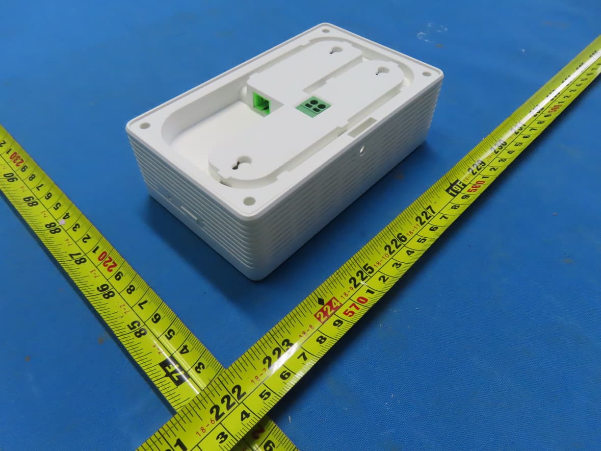
Click to zoom
Application Details
- Equipment Class
- DTS - Digital Transmission System
- Date of Grant
- Jan 21, 2025
- Application Purpose
- Original Equipment
- Equipment Note
- AX1800 Wall Plate Wi-Fi 6 GPON Access Point
- Frequency Range
- 2412.00000000 - 2462.00000000
- Company
- TP-LINK CORPORATION PTE.LTD.
- Country
- Singapore
Documents & Files
Document Text
Text extracted from the exhibit documents filed with the FCC. Open a document above to read the original.
Users Manual
Quick Installation Guide Wall Plate GPON Access Point Note: EAP615GP-Wall is used as an example throughout the Guide. Images may differ from your actual product. ©2024 TP-Link 7106511633 REV1.1.0 Hardware Overview 1 RESET Button FXS Port GPON Port AC Power Input Port ETH1 Port ETH0 Port / ETH0 (PoE OUT) Port * * Actual port may vary by model. LED Button Pre-Installation Checklist 2 Before installation, ensure that you have the following items: • Pre-installed wall junction box (with accessible AC power cable and optical fiber) • Phillips screwdriver • Wire stripper • Wire crimper Installation Steps 3 1. Detach the faceplate of the junction box with a screwdriver. Note: The Standard US wall junction box is used as an example below. Installation may vary slightly with different junction boxes. 1. The product can only be installed by skilled person! 2. An all-pole mains switch in accordance with IEC 62368-1 Annex L shall be incorporated in the electrical installation of the building. And the contact separation of the switch shall not less than 3 mm. 2. Secure the mounting bracket to the junction box with the provided screws. Note: • Do not overtighten the screws. • If the provided screws do not fit the junction box, use the screws attached to the junction box instead. 3. Connect the AC power cable to the EAP’s AC Power Input Port with the provided cord end terminals. Note: For the United States and Canada, the required size of the AC power cable (branch circuit conductor) is 14AWG – 12AWG. For other regions, the size of the AC power cable should be in accordance with the requirements of local building wiring standards but should not exceed 18AWG – 12AWG. 4. Remove the anti-dust plug and connect the optical fiber to the EAP’s GPON Port. Route excess fiber behind the device. 5. Attach the EAP to the mounting bracket. Secure them with the provided screw. 6. Connect your phone to the EAP’s FXS port. If you don’t need phone service, skip this step. * When the Locate feature is activated in the Omada Controller, the LED will flash for 10 minutes to help you locate and identify the device. You can disable this feature manually to stop the device from flashing. On: Working normally/Initializing. Off: Working abnormally/Power off/LED is turned off. Flash: • Flash twice: Initialization is complete. • Flash once per second: The EAP is upgrading. • Quick flash: The EAP is resetting or the Omada Controller is locating the EAP.* • Slow flash: The EAP is in the isolated state. LEDIndication Power GPON Green On: The EAP is registered with the OLT. Flash Green: The EAP is trying to register with the OLT. Flash Red: No optical signal is received or the received signal is too weak. Red On: The EAP is blocked by the OLT or not transmitting an optical signal. Off: The EAP is initializing or works as a mesh AP. With the EAP powered on, press and hold the button for about 5 seconds until the Power LED flashes, then release the button. The EAP will restore to factory settings. Press the button to turn on/off the LEDs. ButtonDescription RESET LED Connect to a phone to make and receive calls over the internet. Connect to a client device to transmit data. * If ETH0 (PoE OUT) Port is provided instead of ETH0 Port, it also supports PoE Out to supply 802.3af power. Connect to a client device to transmit data. Connect to the fiber to transmit optical signals. Connect to the power supply via AC power cable. InterfaceDescription FXS ETH0 / ETH0 (PoE OUT) * ETH1 GPON AC Power Input Peel off the outer covering of the power cable with a wire stripper. Insert the stripped power cable into the cord end terminal. Crimp the cable and the cord end terminal with a wire crimper. Strip Length = Metal Tube Length 123 Method 2: Controller Mode Note: • Before you start, be sure to power up and connect your devices according to the above topology. • A DHCP server (typically a gateway/router with the DHCP function enabled) is required to assign IP addresses to the EAPs and clients in your local network. Choose a type of Omada Controller: Choose a method to set up your EAPs: Software Configuration 4 • Method 1: Standalone Mode For configuring and managing EAPs separately (Convenient for a small network with only a few devices) • Method 2: Controller Mode For configuring and managing EAPs in batches on a central platform, namely an Omada Controller. Method 1: Standalone Mode GPON AP GPON AP Phone Gateway Switch O LTOptical Splitter SIP Server Clients Note: • Before you start, be sure to power up and connect your devices according to the above topology. • A DHCP server (typically a gateway/router with the DHCP function enabled) is required to assign IP addresses to the EAPs and clients in your local network. The Omada Cloud-Based Controller is a good alternative that does not require installing the software controller on a PC or purchasing a hardware controller. Type 1: Omada Cloud-Based Controller Note: • Before you start, be sure to power up and connect your devices according to the above topology. • A DHCP server (typically a gateway/router with the DHCP function enabled) is required to assign IP addresses to the EAPs and clients in your local network. • The Omada Controller must have network access to your Omada devices (the gateway/router, switch, and EAPs) in order to find, adopt, and manage them. Note: • Before you start, be sure to power up and connect your devices according to the above topology. • A DHCP server (typically a gateway/router with the DHCP function enabled) is required to assign IP addresses to the EAPs and clients in your local network. • The Omada Controller must have network access to your Omada devices (the gateway/router, switch, and EAPs) in order to find, adopt, and manage them. • Type 2: Omada Software Controller On a PC with Windows OS or Linux OS, download the software controller from https://www.tp-link.com/support/download/omada-software-controller/. Then run the file and follow the wizard to install and la…
Text truncated - open the document above for the full version.
Users Manual
© 2024 TP-Link 1910013239 REV1.5.0 Regulatory Compliance Wall Plate EAP For Class B EAP with no adapter: FCC Compliance Information Statement Product Name: Omada EAP Model Number: EAP225-Wall / EAP235-Wall / EAP615-Wall / EAP655-Wall / EAP725-Wall / EAP615GP-Wall / EAP625GP-Wall / EAP673-Extender Responsible party: T P-Link USA Corporation Address: 10 Mauchly, Irvine, CA 92618 Website: https://www.tp-link.com/us/ Tel: +1 626 333 0234 Fax: +1 909 527 6804 E -mail: [email protected] This equipment has been tested and found to comply with the limits for a Class B digital device, pursuant to part 15 of the FCC Rules. These limits are designed to provide reasonable protection against harmful interference in a residential installation. This equipment generates, uses and can radiate radio frequency energy and, if not installed and used in accordance with the instructions, may cause harmful interference to radio communications. However, there is no guarantee that interference will not occur in a particular installation. If this equipment does cause harmful interference to radio or television reception, which can be determined by turning the equipment off and on, the user is encouraged to try to correct the interference by one or more of the following measures: •Reorient or relocate the receiving antenna. •Increase the separation between the equipment and receiver. •Con nect the equipment into an outlet on a circuit different from that to which the receiver is connected. •Con sult the dealer or an experienced radio/ TV technician for help. This device complies with part 15 of the FCC Rules. Operation is subject to the following two conditions: 1) This device may not cause harmful interference. 2) This device must accept any interference received, including interference that may cause undesired operation. Any changes or modifications not expressly approved by the party responsible for compliance could void the user’s authority to operate the equipment. Note: The manufacturer is not responsible for any radio or TV interference caused by unauthorized modifications to this equipment. Such modifications could void the user’s authority to operate the equipment. FCC RF Radiation Exposure Statement: This equipment complies with FCC RF radiation exposure limits set forth for an uncontrolled environment. This device and its antenna must not be co-located or operating in conjunction with any other antenna or transmitter. “To comply with FCC RF exposure compliance requirements, this grant is applicable to only Mobile Configurations. The antennas used for this transmitter must be installed to provide a separation distance of at least 20cm from all persons and must not be colocated or operating in conjunction with any other antenna or transmitter.” We, TP-Link USA Corporation, has determined that the equipment shown as above has been shown to comply with the applicable technical standards, FCC part 15. There is no unauthorized change is made in the equipment and the equipment is properly maintained and operated. Issue Date: 2024-10-29 CE Mark Warning This is a class B product. In a domestic environment, this product may cause radio interference, in which case the user may be required to take adequate measures. OPERATING FREQUENCY (the maximum transmitted power) For EAP115-Wall: 2412MHz—2472MHz (20dBm) For EAP225-Wall / EAP230-Wall / EAP235-Wall / EAP615-Wall: 2412MHz—2472MHz (20dBm) 5150MHz—5250MHz (23dBm) For EAP650-Wall / EAP655-Wall / EAP725-Wall / EAP615GP-Wall / EAP625GP-Wall / EAP673-Extender: 2400 MHz -2483.5 MHz (20dBm) 5150MHz—5250MHz (23dBm) 5250 MHz -5350 MHz (23dBm) 5470 MHz -5725 MHz (30dBm) EU Declaration of Conformity For EAP673-Extender, EAP615GP-Wall / EAP625GP-Wall, and APs with adapters: TP-Link hereby declares that the device is in compliance with the essential requirements and other relevant provisions of directives 2014/53/EU, 2009/125/EC, 2011/65/EU and (EU)2015/863. For other APs: TP-Link hereby declares that the device is in compliance with the essential requirements and other relevant provisions of directives 2014/53/EU, 2011/65/EU and (EU)2015/863. The original EU Declaration of Conformity may be found at https://www.tp-link.com/en/ce. RF Exposure Information This device meets the EU requirements (2014/53/EU Article 3.1a) on the limitation of exposure of the general public to electromagnetic fields by way of health protection. The device complies with RF specifications when the device used at 20 cm from your body. National Restrictions For EAP225-Wall / EAP230-Wall / EAP235-Wall / EAP615-Wall / EAP650-Wall / EAP655-Wall / EAP725-Wall / EAP615GP-Wall / EAP625GP-Wall / EAP673-Extender: Attention: This device may only be used indoors in all EU member states, EFTA countries and Northern Ireland. Frequency band: 5150 - 5250 MHz: Indoor use: Inside buildings only. Installations and use inside road vehicles and train carriages are not permitted. Limited outdoor use: If used outdoors, equipment shall not be attached to a fixed installation or to the external body of road vehicles, a fixed infrastructure or a fixed outdoor antenna. Use by unmanned aircraft systems (UAS) is limited to within the 5170 - 5250 MHz band. Frequency band: 5250 - 5350 MHz: Indoor use: Inside buildings only. Installations and use in road vehicles, trains and aircraft are not permitted. Outdoor use is not permitted. Frequency band: 5470 - 5725 MHz: Installations and use in road vehicles, trains and aircraft and use for unmanned aircraft systems (UAS) are not permitted. UKCA Mark UK Declaration of Conformity TP-Link hereby declares that the device is in compliance with the essential requirements and other relevant provisions of the Radio Equipment Regulations 2017. The original UK Declaration of Conformity may be found at https://www.tp-link.com/support/ukca National Restrictions Attention: This device may only be used indoors in Great Britain. UK Canadian Compliance Statement For EAP615-Wall / EAP655-Wall / EAP725-…
Text truncated - open the document above for the full version.
Internal Photos
Project No.: 2410G014 Page 4 of 12 Project No.: 2410G014 Page 5 of 12 Project No.: 2410G014 Page 6 of 12 Project No.: 2410G014 Page 7 of 12 Project No.: 2410G014 Page 8 of 12 Ant. 2 Ant. 1 Project No.: 2410G014 Page 9 of 12 Project No.: 2410G014 Page 10 of 12 Project No.: 2410G014 Page 11 of 12 Project No.: 2410G014 Page 12 of 12
Test Setup Photos
Report No.: BTL-FCCP-1-2410G014 Page 32 of 161 11. EUT TEST PHOTO AC Power Line Conducted Emissions Test Photos Report No.: BTL-FCCP-1-2410G014 Page 33 of 161 Radiated Emissions Test Photos 9 kHz to 30 MHz Report No.: BTL-FCCP-1-2410G014 Page 34 of 161 Radiated Emissions Test Photos 30 MHz to 1 GHz Report No.: BTL-FCCP-1-2410G014 Page 35 of 161 Radiated Emissions Test Photos Band edge & Harmonic(1 GHz to 18 GHz) Report No.: BTL-FCCP-1-2410G014 Page 36 of 161 Radiated Emissions Test Photos Harmonic(18 GHz to 26.5 GHz) Report No.: BTL-FCCP-1-2410G014 Page 37 of 161 Conducted Test Photos
Test Report
Product Model: EAP625GP-Wall Manufacturer: TP-Link Systems Inc. Test Date: 2024.8.19 Tested By: Cui Jiafu TP-Link Systems Inc. 10 Mauchly, Irvine, CA 92618 Index 1. Antenna Distribution ........................................................................................ 3 2. Electrical Characteristics ................................................................................ 3 3. Gain and Radiation Pattern ............................................................................. 4 3.1 Measurement Procedure ........................................................................................... 4 3.2 Test Setup ................................................................................................................. 5 3.3 S Parameter Test Data ............................................................................................. 6 3.4 Antenna Peak Gain ................................................................................................... 7 3.5 Antenna Radiation Pattern ........................................................................................ 7 Page 3 1. Antenna Distribution EAP615GP-Wall 2. Electrical Characteristics Ant1 Frequency 2400~2500 &5150~5895MHz Impedance 50Ohm Antenna Type PIFA Antenna Gain 3.00dBi@2400~2500MHz 3.00dBi@5150~5250MHz 3.00dBi@5250~5350MHz 3.00dBi@5470~5725MHz 3.00dBi@5725~5895MHz Radiation pattern Omni-Directional P/N 6035500222 Ant2 Frequency 2400~2500 &5150~5895MHz Impedance 50Ohm Antenna Type PIFA Antenna Gain 3.00dBi@2400~2500MHz 3.00dBi@5150~5250MHz 3.00dBi@5250~5350MHz 3.00dBi@5470~5725MHz 3.00dBi@5725~5895MHz Radiation pattern Omni-Directional P/N 6035500222 Page 4 3. Gain and Radiation Pattern 3.1 Measurement Procedure This measurement experiment adopted an antenna near-field measurement system, and the diagram of the measurement system was shown in Figure 3-1. The excitation signal was generated by the Keysight E5071C (300kHz-20GHz). Under the control of the central computer, the probe rotated in the θ direction, and the EUT rotated in the φ direction with the turntable. The probe sampling frame received and collected signals in the near-field range of the EUT. The software system which was controlled by the central computer completed the processing, output and display of the test data. Figure 3-1 The test site was a full anechoic chamber with a size of 3.0m×3.1m×2.97m, which was built by GTS Rayzone2800. All six surfaces of the anechoic chamber were pasted with absorbing materials. And the chamber was calibrated by the authoritative third-party lab every year. The antenna anechoic chamber measurement system adopted a 13-probe multi-probe system. The probe antennas were evenly distributed on the spherical surface surrounding the EUT, and theirs operating frequency was 600MHz~8.5GHz. During the measurement, the probe antennas were rotated in the θ direction under the control of the probe holder to sample the near-field data at the θ angle. At the same time, the EUT rotated with the turntable in the φ direction to sample the near field data at the φ angle. The sampling accuracy was 15°. The system diagram was shown in Figure 3-2. From the sampling results, the EUT's near-field test data of θ component, φ component and total component could be obtained. Page 5 Figure 3-2 Before the measurement, calibrated the vector network analyzer, and then connected the input end of each antenna to the output end of the vector network analyzer, and evenly the antennas to be measured. Test Equipment listed below: Equipments Model ManufacturerS/N Cali. Interval Cali. Due Date Chamber Rayzone2800 GTS(General Test System) MY5347043 5 12months 2026/01/15 Vector Network Analyzer E5071C Keysight MY46315238 24months 2026/03/13 GTS MaxSign100 Software V2.1 GTS(General Test System) / / / 3.2 Test Setup The test setup was shown in Figure 3-3, 3-4: Figure 3-3 Page 6 Figure 3-4 3.3 S Parameter Test Data Ant1 Ant2 Page 7 3.4 Antenna Peak Gain Frequency 2.45GHz 2400~2500MHz 5.2GHz 5150~5250MHz 5.3GHz 5250~5350MHz 5.6GHz 5470~5725MHz Ant1 MaxGain(dBi) 3.00 3.00 3.00 3.00 Ant2 MaxGain(dBi) 3.00 3.00 3.00 3.00 Ant1 Polarization/Φ (°)/θ(°) Theta/135/90 Theta/90/90 Theta/0/90 Theta/75/90 Ant2 Polarization/Φ (°)/θ(°) Theta/165/90 Theta/105/90 Theta/105/90 Theta/105/90 Max Gain(dBi) 3.00 3.00 3.00 3.00 Frequency 5.8GHz 5725~5895MHz Ant1 MaxGain(dBi) 3.00 Ant2 MaxGain(dBi) 3.00 Ant1 Polarization/Φ (°)/θ(°) Theta/75/90 Ant2 Polarization/Φ (°)/θ(°) Theta/105/90 Max Gain(dBi) 3.00 3.5 Antenna Radiation Pattern Ant1 Ant2
Test Report
Report No.: BTL-FCCP-1-2410G014 Page 151 of 161 Test Mode TX AX(HE40) Mode_Ant. 1 Reference Level-CH03 Reference Level-06 Reference Level-CH09 Bandedge-CH03 Bandedge-CH09 Report No.: BTL-FCCP-1-2410G014 Page 152 of 161 CH03 – 10th Harmonic of the fundamental frequency CH06 – 10th Harmonic of the fundamental frequency CH09 – 10th Harmonic of the fundamental frequency Report No.: BTL-FCCP-1-2410G014 Page 153 of 161 Test Mode TX AX(HE40) Mode_Ant. 2 Reference Level-CH03 Reference Level-06 Reference Level-CH09 Bandedge-CH03 Bandedge-CH09 Report No.: BTL-FCCP-1-2410G014 Page 154 of 161 CH03 – 10th Harmonic of the fundamental frequency CH06 – 10th Harmonic of the fundamental frequency CH09 – 10th Harmonic of the fundamental frequency Report No.: BTL-FCCP-1-2410G014 Page 155 of 161 APPENDIX H - POWER SPECTRAL DENSITY Report No.: BTL-FCCP-1-2410G014 Page 156 of 161 Test Mode TX B Mode_Ant. 1 Channel Frequency (MHz) Power Spectral Density (dBm/3kHz) Max. Limit (dBm/3kHz) Result 01 2412 -3.72 7.99 Complies 06 2437 -4.65 7.99 Complies 11 2462 -3.83 7.99 Complies CH01 CH06 CH11 Test Mode TX B Mode_Ant. 2 Channel Frequency (MHz) Power Spectral Density (dBm/3kHz) Max. Limit (dBm/3kHz) Result 01 2412 -3.82 7.99 Complies 06 2437 -4.11 7.99 Complies 11 2462 -4.29 7.99 Complies CH01 CH06 CH11 Test Mode TX B Mode_Total Channel Frequency (MHz) Power Spectral Density (dBm/3kHz) Max. Limit (dBm/3kHz) Result 01 2412 -0.76 7.99 Complies 06 2437 -1.36 7.99 Complies 11 2462 -1.04 7.99 Complies Report No.: BTL-FCCP-1-2410G014 Page 157 of 161 Test Mode TX G Mode_Ant. 1 Channel Frequency (MHz) Power Spectral Density (dBm/3kHz) Max. Limit (dBm/3kHz) Result 01 2412 -8.77 7.99 Complies 06 2437 -5.70 7.99 Complies 11 2462 -8.46 7.99 Complies CH01 CH06 CH11 Test Mode TX G Mode_Ant. 2 Channel Frequency (MHz) Power Spectral Density (dBm/3kHz) Max. Limit (dBm/3kHz) Result 01 2412 -7.54 7.99 Complies 06 2437 -6.15 7.99 Complies 11 2462 -7.62 7.99 Complies CH01 CH06 CH11 Test Mode TX G Mode_Total Channel Frequency (MHz) Power Spectral Density (dBm/3kHz) Max. Limit (dBm/3kHz) Result 01 2412 -5.10 7.99 Complies 06 2437 -2.91 7.99 Complies 11 2462 -5.01 7.99 Complies Report No.: BTL-FCCP-1-2410G014 Page 158 of 161 Test Mode TX N(HT20) Mode_Ant. 1 Channel Frequency (MHz) Power Spectral Density (dBm/3kHz) Max. Limit (dBm/3kHz) Result 01 2412 -9.10 7.99 Complies 06 2437 -5.91 7.99 Complies 11 2462 -6.59 7.99 Complies CH01 CH06 CH11 Test Mode TX N(HT20) Mode_Ant. 2 Channel Frequency (MHz) Power Spectral Density (dBm/3kHz) Max. Limit (dBm/3kHz) Result 01 2412 -8.51 7.99 Complies 06 2437 -5.57 7.99 Complies 11 2462 -7.41 7.99 Complies CH01 CH06 CH11 Test Mode TX N(HT20) Mode_Total Channel Frequency (MHz) Power Spectral Density (dBm/3kHz) Max. Limit (dBm/3kHz) Result 01 2412 -5.78 7.99 Complies 06 2437 -2.73 7.99 Complies 11 2462 -3.97 7.99 Complies Report No.: BTL-FCCP-1-2410G014 Page 159 of 161 Test Mode TX N(HT40) Mode_Ant. 1 Channel Frequency (MHz) Power Spectral Density (dBm/3kHz) Max. Limit (dBm/3kHz) Result 03 2422 -10.91 7.99 Complies 06 2437 -10.59 7.99 Complies 09 2452 -12.46 7.99 Complies CH03 CH06 CH09 Test Mode TX N(HT40) Mode_Ant. 2 Channel Frequency (MHz) Power Spectral Density (dBm/3kHz) Max. Limit (dBm/3kHz) Result 03 2422 -10.68 7.99 Complies 06 2437 -10.44 7.99 Complies 09 2452 -10.25 7.99 Complies CH03 CH06 CH09 Test Mode TX N(HT40) Mode_Total Channel Frequency (MHz) Power Spectral Density (dBm/3kHz) Max. Limit (dBm/3kHz) Result 03 2422 -7.78 7.99 Complies 06 2437 -7.50 7.99 Complies 09 2452 -8.21 7.99 Complies Report No.: BTL-FCCP-1-2410G014 Page 160 of 161 Te s t Mode TX AX(HE20) Mode_Ant. 1 Channel Frequency (MHz) Power Spectral Density (dBm/3kHz) Max. Limit (dBm/3kHz) Result 01 2412 -8.40 7.99 Complies 06 2437 -7.29 7.99 Complies 11 2462 -7.41 7.99 Complies CH01 CH06 CH11 Test Mode TX AX(HE20) Mode_Ant. 2 Channel Frequency (MHz) Power Spectral Density (dBm/3kHz) Max. Limit (dBm/3kHz) Result 01 2412 -10.29 7.99 Complies 06 2437 -7.08 7.99 Complies 11 2462 -8.26 7.99 Complies CH01 CH06 CH11 Test Mode TX AX(HE20) Mode_Total Channel Frequency (MHz) Power Spectral Density (dBm/3kHz) Max. Limit (dBm/3kHz) Result 01 2412 -6.23 7.99 Complies 06 2437 -4.17 7.99 Complies 11 2462 -4.80 7.99 Complies Report No.: BTL-FCCP-1-2410G014 Page 161 of 161 Test Mode TX AX(HE40) Mode_Ant. 1 Channel Frequency (MHz) Power Spectral Density (dBm/3kHz) Max. Limit (dBm/3kHz) Result 03 2422 -12.56 7.99 Complies 06 2437 -11.21 7.99 Complies 09 2452 -12.72 7.99 Complies CH03 CH06 CH09 Test Mode TX AX(HE40) Mode_Ant. 2 Channel Frequency (MHz) Power Spectral Density (dBm/3kHz) Max. Limit (dBm/3kHz) Result 03 2422 -12.56 7.99 Complies 06 2437 -11.18 7.99 Complies 09 2452 -11.29 7.99 Complies CH03 CH06 CH09 Test Mode TX AX(HE40) Mode_Total Channel Frequency (MHz) Power Spectral Density (dBm/3kHz) Max. Limit (dBm/3kHz) Result 03 2422 -9.55 7.99 Complies 06 2437 -8.18 7.99 Complies 09 2452 -8.94 7.99 Complies End of Test Report
Test Report
Report No.: BTL-FCCP-1-2410G014 Page 132 of 161 CH01 – 10th Harmonic of the fundamental frequency CH06 – 10th Harmonic of the fundamental frequency CH11 – 10th Harmonic of the fundamental frequency Report No.: BTL-FCCP-1-2410G014 Page 133 of 161 Test Mode TX B Mode_Ant. 2 Reference Level-CH01 Reference Level-06 Reference Level-CH11 Bandedge-CH01 Bandedge-CH11 Report No.: BTL-FCCP-1-2410G014 Page 134 of 161 CH01 – 10th Harmonic of the fundamental frequency CH06 – 10th Harmonic of the fundamental frequency CH11 – 10th Harmonic of the fundamental frequency Report No.: BTL-FCCP-1-2410G014 Page 135 of 161 Test Mode TX G Mode_Ant. 1 Reference Level-CH01 Reference Level-06 Reference Level-CH11 Bandedge-CH01 Bandedge-CH11 Report No.: BTL-FCCP-1-2410G014 Page 136 of 161 CH01 – 10th Harmonic of the fundamental frequency CH06 – 10th Harmonic of the fundamental frequency CH11 – 10th Harmonic of the fundamental frequency Report No.: BTL-FCCP-1-2410G014 Page 137 of 161 Test Mode TX G Mode_Ant. 2 Reference Level-CH01 Reference Level-06 Reference Level-CH11 Bandedge-CH01 Bandedge-CH11 Report No.: BTL-FCCP-1-2410G014 Page 138 of 161 CH01 – 10th Harmonic of the fundamental frequency CH06 – 10th Harmonic of the fundamental frequency CH11 – 10th Harmonic of the fundamental frequency Report No.: BTL-FCCP-1-2410G014 Page 139 of 161 Test Mode TX N(HT20) Mode_Ant. 1 Reference Level-CH01 Reference Level-06 Reference Level-CH11 Bandedge-CH01 Bandedge-CH11 Report No.: BTL-FCCP-1-2410G014 Page 140 of 161 CH01 – 10th Harmonic of the fundamental frequency CH06 – 10th Harmonic of the fundamental frequency CH11 – 10th Harmonic of the fundamental frequency Report No.: BTL-FCCP-1-2410G014 Page 141 of 161 Test Mode TX N(HT20) Mode_Ant. 2 Reference Level-CH01 Reference Level-06 Reference Level-CH11 Bandedge-CH01 Bandedge-CH11 Report No.: BTL-FCCP-1-2410G014 Page 142 of 161 CH01 – 10th Harmonic of the fundamental frequency CH06 – 10th Harmonic of the fundamental frequency CH11 – 10th Harmonic of the fundamental frequency Report No.: BTL-FCCP-1-2410G014 Page 143 of 161 Test Mode TX N(HT40) Mode_Ant. 1 Reference Level-CH03 Reference Level-06 Reference Level-CH09 Bandedge-CH03 Bandedge-CH09 Report No.: BTL-FCCP-1-2410G014 Page 144 of 161 CH03 – 10th Harmonic of the fundamental frequency CH06 – 10th Harmonic of the fundamental frequency CH09 – 10th Harmonic of the fundamental frequency Report No.: BTL-FCCP-1-2410G014 Page 145 of 161 Test Mode TX N(HT40) Mode_Ant. 2 Reference Level-CH03 Reference Level-06 Reference Level-CH09 Bandedge-CH03 Bandedge-CH09 Report No.: BTL-FCCP-1-2410G014 Page 146 of 161 CH03 – 10th Harmonic of the fundamental frequency CH06 – 10th Harmonic of the fundamental frequency CH09 – 10th Harmonic of the fundamental frequency Report No.: BTL-FCCP-1-2410G014 Page 147 of 161 Test Mode TX AX(HE20) Mode_Ant. 1 Reference Level-CH01 Reference Level-06 Reference Level-CH11 Bandedge-CH01 Bandedge-CH11 Report No.: BTL-FCCP-1-2410G014 Page 148 of 161 CH01 – 10th Harmonic of the fundamental frequency CH06 – 10th Harmonic of the fundamental frequency CH11 – 10th Harmonic of the fundamental frequency Report No.: BTL-FCCP-1-2410G014 Page 149 of 161 Test Mode TX AX(HE20) Mode_Ant. 2 Reference Level-CH01 Reference Level-06 Reference Level-CH11 Bandedge-CH01 Bandedge-CH11 Report No.: BTL-FCCP-1-2410G014 Page 150 of 161 CH01 – 10th Harmonic of the fundamental frequency CH06 – 10th Harmonic of the fundamental frequency CH11 – 10th Harmonic of the fundamental frequency
Test Report
Report No.: BTL-FCCP-1-2410G014 Page 1 of 161 FCC Radio Test Report FCC ID: 2BCGWEAP625GPW This report concerns: Original Grant Project No. : 2410G014 Equipment : AX1800 Wall Plate Wi-Fi 6 GPON Access Point Brand Name : tp-link Test Model : EAP625GP-Wall Series Model : N/A Applicant : TP-LINK CORPORATION PTE. LTD. Address : 7 Temasek Boulevard #29-03 Suntec Tower One, Singapore 038987 Manufacturer : TP-LINK CORPORATION PTE. LTD. Address : 7 Temasek Boulevard #29-03 Suntec Tower One, Singapore 038987 Date of Receipt : Oct. 14, 2024 Date of Test : Oct. 17, 2024 ~ Dec. 05, 2024 Issued Date : Jan. 17, 2025 Report Version : R00 Test Sample : Engineering Sample No.: DG2024101431 for AC power line conducted emissions and radiated, DG2024101430 for others. Standard(s) : FCC CFR Title 47, Part 15, Subpart C The above equipment has been tested and found compliance with the requirement of the relative standards by BTL Inc. Prepared by : Antony Liang Approved by : Chay Cai Room 108-116, 309-310, Building 2, No.1, Yile Road, Songshan Lake Zone, Dongguan City, Guangdong, People’s Republic of China. Te l : + 8 6-769-8318-3000 Web: www.newbtl.com Service mail: [email protected] Report No.: BTL-FCCP-1-2410G014 Page 2 of 161 Declaration BTL represents to the client that testing is done in accordance with standard procedures as applicable and that test instruments used has been calibrated with standards traceable to international standard(s) and/or national standard(s). BTL's reports apply only to the specific samples tested under conditions. It is manufacture’s responsibility to ensure that additional production units of this model are manufactured with the identical electrical and mechanical components. BTL assumes no responsibility for the data provided by the customer, any statements, inferences or generalizations drawn by the customer or others from the reports issued by BTL. The report must not be used by the client to claim product certification, approval, or endorsement by A2LA or any agency of the U.S. Government. This report is the confidential property of the client. As a mutual protection to the clients, the public and ourselves, the test report shall not be reproduced, except in full, without our written approval. BTL’s laboratory quality assurance procedures are in compliance with the ISO/IEC 17025: 2017 requirements, and accredited by the conformity assessment authorities listed in this test report. BTL is not responsible for the sampling stage, so the results only apply to the sample as received. The information, data and test plan are provided by manufacturer which may affect the validity of results, so it is manufacturer’s responsibility to ensure that the apparatus meets the essential requirements of applied standards and in all the possible configurations as representative of its intended use. Limitation For the use of the authority's logo is limited unless the Test Standard(s)/Scope(s)/Item(s) mentioned in this test report is (are) included in the conformity assessment authorities acceptance respective. Please note that the measurement uncertainty is provided for informational purpose only and are not use in determining the Pass/Fail results. Report No.: BTL-FCCP-1-2410G014 Page 3 of 161 Table of Contents Page REPORT ISSUED HISTORY 6 1 . APPLICABLE STANDARDS 7 2 . SUMMARY OF TEST RESULTS 7 2.1 TEST FACILITY 8 2.2 MEASUREMENT UNCERTAINTY 8 2.3 TEST ENVIRONMENT CONDITIONS 9 3 . GENERAL INFORMATION 10 3.1 GENERAL DESCRIPTION OF EUT 10 3.2 DESCRIPTION OF TEST MODES 12 3.3 PARAMETERS OF TEST SOFTWARE 15 3.4 DUTY CYCLE 16 3.5 BLOCK DIAGRAM SHOWING THE CONFIGURATION OF SYSTEM TESTED 18 3.6 SUPPORT UNITS 18 3.7 CUSTOMER INFORMATION DESCRIPTION 18 4 . AC POWER LINE CONDUCTED EMISSIONS 19 4.1 LIMIT 19 4.2 TEST PROCEDURE 19 4.3 DEVIATION FROM TEST STANDARD 19 4.4 TEST SETUP 20 4.5 EUT OPERATION CONDITIONS 20 4.6 TEST RESULTS 20 5 . RADIATED EMISSIONS 21 5.1 LIMIT 21 5.2 TEST PROCEDURE 22 5.3 DEVIATION FROM TEST STANDARD 23 5.4 TEST SETUP 23 5.5 EUT OPERATION CONDITIONS 25 5.6 TEST RESULTS - 9 KHZ TO 30 MHZ 2…
Text truncated - open the document above for the full version.
Contact Information
Applicant
sarah wang
[email protected]Fax: +86 755 21534921
Technical Contact
Test Firm
BTL Inc. (Dongguan)Sophia Huang
Technical Specifications
| # | Rule Parts | Frequency Range | Power Output |
|---|---|---|---|
| 1 | 15C | 2.41 GHz - 2.46 GHz | 260.00 mW |