2BCIC-M1projector
SHEN ZHEN GUO WEI NETWORK SERVICE LIMITED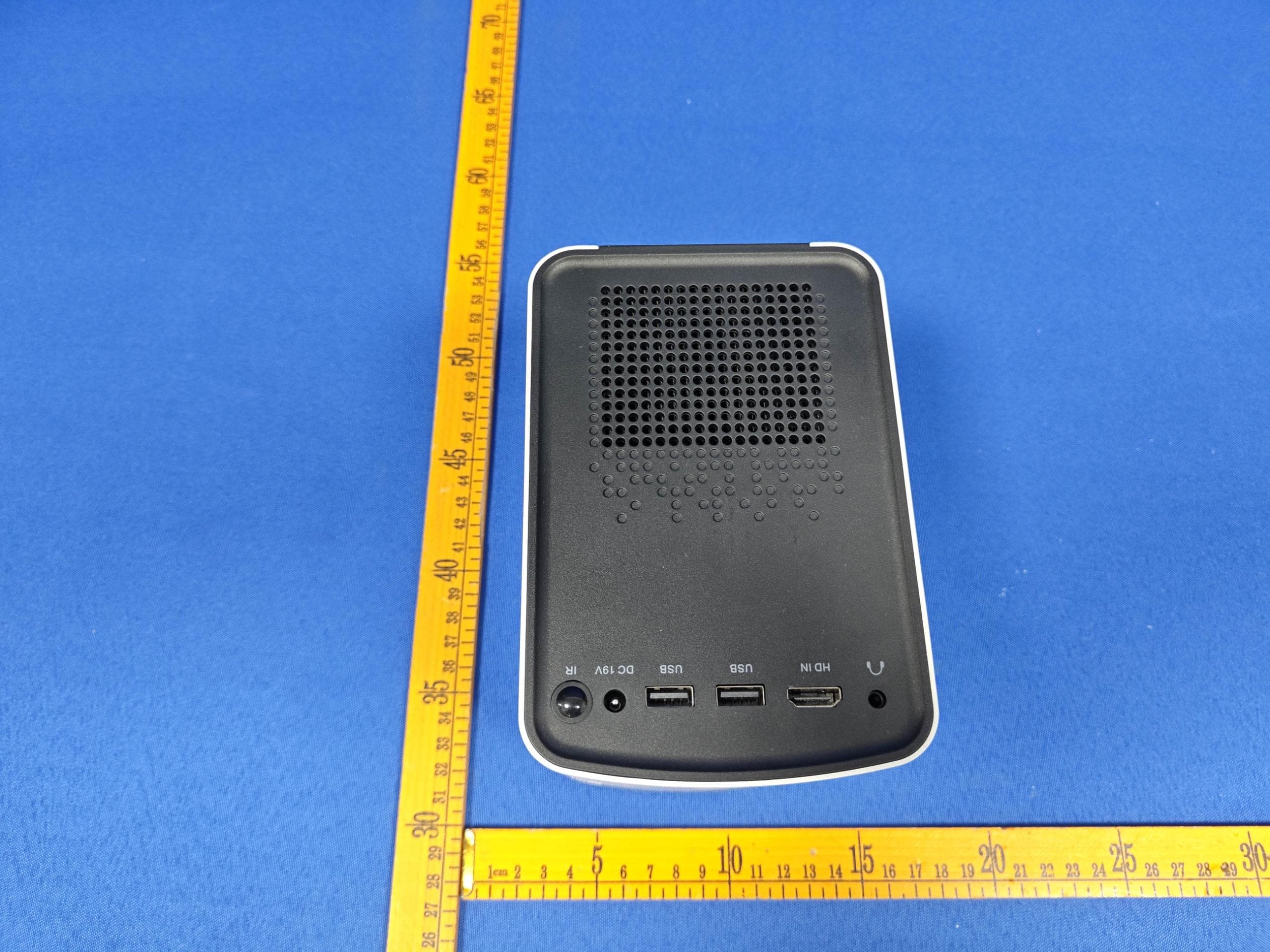
Click to zoom
Application Details
- Equipment Class
- DTS - Digital Transmission System
- Date of Grant
- Aug 30, 2023
- Application Purpose
- Original Equipment
- Date of Application
- Aug 30, 2023
- Equipment Note
- projector
- Frequency Range
- 2412.00000000 - 2462.00000000
- Country
- China
Documents & Files
Document Text
Text extracted from the exhibit documents filed with the FCC. Open a document above to read the original.
Users Manual
109 SmartLCD Projector Manual M1 Contents I.Product Precautions II.Product Introduction Ill. Remote Control IV. Connection V. Introduction to the Main Functions of the system interface VI. OSD Menu Setting Vll. Projection Size Distance Table 1 2 4 5 9 14 15 l.Product Precautions 1. Please read this manual carefully before. 2. In order to ensure the stability of power supply of this machine, please use the power supply line conforming to the national power consumption standard and the power socket with grounding and other protection measures. 3. Please use the power supply type indicated on the projector for power supply. 4. Please do not open and dismantle the machine by yourself, otherwise our company will not undertake free warranty service. 5. Please do not look directly at the projector lens when the projector is working, so as not to hurt your eyes. 6. Please do not place the projector on articles that may block the vents, such as cloth and blankets. 7.This product does not have waterproof function, so water sprinkling or splashing should be avoided, and vases, cups and other items containing liquid should not be placed next to the product. 8. In order to prevent electric shock,remember not to make this machine rain or water injected into it. 9. If you don't use this product for a long time, please unplug the power cord. 10. When transporting this product, please use the original foam of the machine. 11. lf you find that the product is damaged, please do not try to repair it yourself,please contact the dealer. 12.Please use itin an environment of 5-35C,and use it in an environmentbelow 2000Mabove sealevel. Package Contents: This product contains the following components,if there is any missing,please contact the dealerimmediately. Projector Remote control 19VDC Adapter Operating Manual 1pcs 1pcs 1pcs 1pcs Il.ProductIntroduction Front ViewBack View 7 6 1 2 3 4 5 9 10 12 11 Top ViewBottom View HDMIinterface U S B i n t e r f a c e Audio 19V DC interface Infrared receiver window A i r I n l e t Lens Outlet Lens focusing ring On/off key Foot pad S u p p o r t s c r e w h o l e 8 1 2 3 4 5 6 7 8 9 10 11 12 Note: Please do not look directly at the camera, so as not to hurt your eyes!!! Ill Remote Control Infrared Remote Controller 1 2 10 15 5 7 9 8 6 3 4 12 13 14 11 16 17 .On/Off .Mute .Volume- .Volume+ .Menu .Up .Left .Right .Down .OK .Return .Signal .Home .Trapezoid+ .Trapezoid- .YouTube .Prime video 1 2 3 4 5 6 7 8 9 10 11 12 13 14 15 16 17 IV.Connection Warning: As a safety precaution, disconnect the projector and all connected device before connecting the cables 1.Turn on Find the random standard adapter and remote control. Turn on the machine, turn on the red light during the power-on process, press t h e m a c h i n e b o d y s t a r t u p k e y o r t h e r e m o t e c o n t r o l l e r s t a r t u p key, a n d t h e n t h e i n d i c a t o r l i g h t g o e s o u t . A f t e r t h e s tartup logo appears, it enters the system interface and the machine starts to work. 2.lmagefocusing/trapezoidalcorrection l m a g e f o c u s i n g : A f t e r t h e p r o j e c t o r i s t u r n e d o n , t h e m a i n interface appears. When the projected picture is not clear, adjust the lens focusing ring until the projected picture is clear Lens focusing ring 1 Trapezoidal correction: When the projector is put up or down, the electronic trapezoidal correction function is needed to realize image normalization. 2 ( 1 ) M a n u a l t r a p e z o i d c o r r e c t i o n : M o v e t h e c u r s o r t o S e t t i n g in t h e m a i n i n t e r f a c e a n d o p e n S e t t i n g - P r o j e c t i o n Setting- Horizontal/Vertical Correction. W h e n t h e m a c h i n e i s p r o j e c t e d u p a n d d o w n, you can use vertical trapezoidal adjustment (press Up and Down) to correct t h e c o r r e s p o n d i n g v a l u e t o n o r m a l p i c t u r e . W h e n t h e m a c h i n e t o the left or right projection, you can use the horizontal trapezoidal adjustment (press Left and Right) to correct the corresponding value to the normal picture (2) Four-point trapezoid correction: Move the cursor to Setting in the main interface, and open Setting-Projection Setting-Four- corner trapezoid correction. (This function is needed when the m a c h i n e t i l t s u p a n d d o w n , l e f t a n d r i g h t d i r e c t i o n s a t t h e s a m e time). Four- point trapezoidal correction operation instructions: press OK to switch the four corners, and press the upper, lower, left and right direction keys to switch values after selection. After adjusting OK for one corner, press OK to switch to the next corner, repeat the above steps to adjust the four corners to be appropriate, and the picture is normal. (press Menu to reset) 3.Projector signal source inputselection When the projector is connected with the external device interface, the projector needs to use the remote controller to move to the corresponding signal channel icon in the main interface, or press the channel selection key to select the corresponding input channel for connection, such as HDMI,MEDIA, etc. After the machine is turned on, the cursor of the remote controller can be moved to the corresponding position in the main interface, and the input signal source can be entered by pressing the confirmation key or directly use the remote controller to press the signal selection key to directly call out the signal channel and select the HDMI channel to enter. Press the confirm key to enter the corresponding channel. Exit the HDMI channel and press the return key to return to the maininterface 4.Projector connection setting (1)connector and HDMI device Prepare an HDMI cabel with one end connected to the HDMI interface of the projector and the other end connected to the device(such as computer,HD player,DVD,etc.) and enter HDMI mode by pressing the menu key. (2)Connect USB flash drive After connecting the USB flash drive to the machine, move the icon on t…
Text truncated - open the document above for the full version.
Cover Letter(s)
Sincerely, Name/Title: kao Luo/manager Company: SHEN ZHEN GUO WEI NETWORK SERVICE LIMITED Address: FLAT/RM D18 3/F WONG KING INDUSTRIAL BUILDING NO.2 TAI YAU STREET KL China Phone: +86-18617086542 Fax: +86-18617086542 E-Mail: [email protected]
External Photos
FCCID:2BCIC-M1 FCCID:2BCIC-M1 FCCID:2BCIC-M1 FCCID:2BCIC-M1
ID Label/Location Info
Product:projector Model:M1 FCCID:2BCIC-M1 SHENZHENGUOWEINETWORKSERVICELIMITED
Internal Photos
FCCID:2BCIC-M1 FCCID:2BCIC-M1 FCCID:2BCIC-M1 ANT FCCID:2BCIC-M1 FCCID:2BCIC-M1 FCCID:2BCIC-M1
RF Exposure Info
Report No.: PTC23071005601E-FC03 Page 1 of 7 FCC TEST REPORT FCC ID: 2BCIC-M1 Product : projector Model Name : M1,M2, M3, Y1, Y2, Y3, Z1, Z2, Z3 Brand : N/A Report No. : PTC23071005601E-FC03 Prepared for SHEN ZHEN GUO WEI NETWORK SERVICE LIMITED FLAT/RM D18 3/F WONG KING INDUSTRIAL BUILDING NO.2 TAI YAU STREET KL Prepared by Precise Testing & Certification Co., Ltd. Building 1, No. 6, Tongxin Road, Dongcheng Street, Dongguan, Guangdong, China. Report No.: PTC23071005601E-FC03 Page 2 of 7 TEST RESULT CERTIFICATION Applicant’s name : SHEN ZHEN GUO WEI NETWORK SERVICE LIMITED Address : FLAT/RM D18 3/F WONG KING INDUSTRIAL BUILDING NO.2 TAI YAU STREET KL Manufacture's name : SHEN ZHEN GUO WEI NETWORK SERVICE LIMITED Address : FLAT/RM D18 3/F WONG KING INDUSTRIAL BUILDING NO.2 TAI YAU STREET KL Product name : projector Model name : M1,M2, M3, Y1, Y2, Y3, Z1, Z2, Z3 Test procedure : FCC CFR47 Part 1.1307(b)(1) Test Date : Jul. 12, 2023 to Aug. 12, 2023 Date of Issue : Aug. 22, 2023 Test Result : PASS This device described above has been tested by PTC, and the test results show that the equipment under test (EUT) is in compliance with the FCC requirements. And it is applicable only to the tested sample identified in the report. This report shall not be reproduced except in full, without the written approval of PTC, this document may be altered or revised by PTC, personal only, and shall be noted in the revision of the document. Test Engineer: Simon Pu / Engineer Technical Manager: Ronnie Liu / Manager Report No.: PTC23071005601E-FC03 Page 3 of 7 Contents Page 2 TEST SUMMARY .............................................................................................................................................. 4 3 GENERAL INFORMATION ............................................................................................................................. 5 3.1 GENERAL DESCRIPTION OF E.U.T. ......................................................................................................... 5 4 RF EXPOSURE ................................................................................................................................................. 6 4.1 REQUIREMENTS ....................................................................................................................................... 6 4.2 THE PROCEDURES / LIMIT ........................................................................................................................ 6 4.3 MPE CALCULATION METHOD ................................................................................................................. 7 4.4 TEST RESULT .......................................................................................................................................... 7 Report No.: PTC23071005601E-FC03 Page 4 of 7 2 Test Summary Test Items Test Requirement Result Maximum Permissible Exposure (Exposure of Humans to RF Fields) 15.247 (i) PASS Remark: N/A: Not Applicable Report No.: PTC23071005601E-FC03 Page 5 of 7 3 General Information 3.1 General Description of E.U.T. Product Name : projector Model Name : M1 Additional model : M2, M3, Y1, Y2, Y3, Z1, Z2, Z3 Model difference : The difference between the additional model M2, M3, Y1, Y2, Y3, Z1, Z2, Z3 and the test model M1 is only the model name and appearance color are different, and the rest are the same. Specification : 802.11b/g/n HT20/HT40 BT BDR+EDR Operation Frequency : 2412-2462MHz for 802.11b/g/ n(HT20/HT40) 2402-2480MHz Number of Channel : 11 channels for 802.11b/g/ n(HT20/HT40) 79 channels for BDR+EDR Type of Modulation : DSSS with DBPSK/DQPSK/CCK for 802.11b; OFDM with BPSK/QPSK/16QAM/64QAM for 802.11g/n; Antenna installation : FPC antenna Antenna Gain : 2.07 dBi Power supply : Input:19.0V3.42A Hardware Version : VER00.02 Software Version : Ver 2.1.3.0 Git 6dce6e,May 12 2023,07:18:47 Report No.: PTC23071005601E-FC03 Page 6 of 7 4 RF Exposure Test Requirement : FCC Part 1.1307(b)(1) Evaluation Method : KDB 447498 D01 General RF Exposure Guidance v06 4.1 Requirements Systems operating under the provisions of this section shall be operated in a manner that ensures that the public is not exposed to radio frequency energy levels in excess limit for maximum permissible exposure. In accordance with 47 CFR FCC Part 2 Subpart J, section 2.1091 this device has been defined as a mobile device whereby a distance of 0.2 m normally can be maintained between the user and the device. 4.2 The procedures / limit (A) Limits for Occupational / Controlled Exposure Frequency Range (MHz) Electric Field Strength (E) (V/m) Magnetic Field Strength (H) (A/m) Power Density (S) (mW/ cm 2 ) Averaging Time |E| 2 ,|H| 2 or S (minutes) 0.3-3.0 614 1.63 (100)* 6 3.0-30 1842 / f 4.89 / f (900 / f)* 6 30-300 61.4 0.163 1.0 6 300-1500 F/300 6 1500-100,000 5 6 (B) Limits for General Population / Uncontrolled Exposure Frequency Range (MHz) Electric Field Strength (E) (V/m) Magnetic Field Strength (H) (A/m) Power Density (S) (mW/ cm2) Averaging Time |E|2,|H|2 or S (minutes) 0.3-1.34 614 1.63 (100)* 30 1.34-30 824/f 2.19/f (180/f)* 30 30-300 27.5 0.073 0.2 30 300-1500 F/1500 30 1500-100,000 1.0 30 Note: f = frequency in MHz ; *Plane-wave equivalent power density Report No.: PTC23071005601E-FC03 Page 7 of 7 4.3 MPE Calculation Method E (V/m) = d G P 30 Power Density: Pd (W/m²) = 377 2 E E = Electric field (V/m) P = Peak RF output power (W) G = EUT Antenna numeric gain (numeric) d = Separation distance between radiator and human body (m) The formula can be changed to Pd = 2 377 30 d G P θφ From the peak EUT RF output power, the minimum mobile separation distance, d=0.2m, as well as the gain of the used antenna, the RF power density can be obtained 4.4 Test Result Mode Antenna Gain (numeric) Max. Peak Output Power (dBm) Tune up tolerance (dBm) Max Tune Up Power (mW) Power Density (mW/cm2) Limit of Power Density (mW/cm2) Result 2402(BDR) 1.61 2.18 2.18±1 2.079697 0.000666 1 Pass Wi-Fi(…
Text truncated - open the document above for the full version.
Test Report
1 SHEN ZHEN GUO WEI NETWORK SERVICE LIMITED 规 格 书 SPECIFICATION FOR APPROVAL 供应商名称: Supplier: SHEN ZHEN GUO WEI NETWORK SERVICE LIMITED 制造商名称: Manufacturer: 客户名称: Customer: 产品名称: Part Name: FPC天线(L=75MM) 产品型号: Model: W62 0120-B-01-P 客户物料编码: Customer Part No: (填写灵犀料号) 规格: Specification: (L=75MM) 制表日期: Date: 2022.10.27 电话:0769-85322066 传真:0769-85440789 网址: www.teconn.com.cn 供应商(盖章): 地址:FLAT/RM D18 3/F WONG KING INDUSTRIAL BUILDING NO.2 TAI YAU STREET KL E-MAIL: 供应商确认 Supplier 客户确认 Customer 拟 制 DRAFTER 审 核 CHECK 批 准 APPROVER 审 核 CHECK 批 准 APPROVER Yonglijiang Zhangjing Lihubing SHEN ZHEN GUO WEI NETWORK SERVICE LIMITED 3 Change history 更 改 记 录 Rev Date Reason for change (content) Drafter Check 1.0 2022.22.27 New release 雍丽江 张景 - 1 - SHEN ZHEN GUO WEI NETWORK SERVICE LIMITED SPECIFICATION 规格书 Customer Name / Product name FPC 天线 Product number W620120-B-01-P Customer P/N : Prepared By 张景 Date 2022年10月27日 频率范围Frequency range 2.0Dbi@2400 ~ 2500 MHz 1.6Dbi@5150 ~ 5850 MHz 驻波比系数VSWR <2.5 输入阻抗Input Impedance 50±5(Ω) 极化方式Polarization 垂直极化 Vertical Polarization 半功率波束(3dB)HPW 180°H-plane 120°E-plane SHEN ZHEN GUO WEI NETWORK SERVICE LIMITED - 2 - Revision History 1 Technical Summary This report summarizes the electrical r esults of the proposed antenna to support the W620120-B-01-P program. We test the antenna with the latest version handset. And it seems to b e acceptable. 2 General Description 2.1 Components/Part revisions VSWR: Voltage Standing Wave Rate. 3 Mechanical Description PhysicalImage 4 Electrical Performance 4.1Set-up 4.1.1 VSWR VSWR measurements (S11) were performed using an Agilent 8753D Network Analyzer and the previously described test fixture. Coaxial chokes were used to mitigate surface currents on the outside of the cabling. The testing was performed in free space. 4.1.2 Gain & Radiation Patterns The gain of the antenna was measured in the Lxc’s anechoic chamber. Coaxial chokes on the feed cable were used to mitigate surface currents. The chamber provides less than –30 dB reflectivity from 300 MHz through 6 GHz and an 18” diameter spherical quite zone. The measurement results are calibrated using both dipole and leaky wave horn standards. 4.1.3 Matching Circuit Description No changed.. DateRevision Description of Changes 2022.10.27 RA Measured with 2.4GHz/5.8GHz sample. SHEN ZHEN GUO WEI NETWORK SERVICE LIMITED - 3 - 5 Antenna - Radiation Pattern Test Data 2400 MHz 2410 MHz 2420 MHz 2430 MHz 2440 MHz 2450 MHz 2460 MHz 2470 MHz 2480 MHz SHEN ZHEN GUO WEI NETWORK SERVICE LIMITED - 4 - 2490 MHz 2500 MHz XYXZYZ SHEN ZHEN GUO WEI NETWORK SERVICE LIMITED - 5 - 5150 MHz 5250 MHz 5350 MHz 5450 MHz 5550 MHz 5650 MHz 5750 MHz 5850 MHz SHEN ZHEN GUO WEI NETWORK SERVICE LIMITED - 6 - XY XZ YZ 6.Plots VSWR 注:驻波系数的标准值 SHEN ZHEN GUO WEI NETWORK SERVICE LIMITED - 7 - 注:回损的标准值 7 Reliability tests 7.1 Test content N o 试验项目 试验方法 判定基准 1 盐水喷雾试验 把盐浓度5%的溶液喷 雾24H 不能有变色,歪(变形)脱落等的缺点 腐蚀面积不能过大 7.2Test results NO 样品数 试验期间 实验结果 备注 150PCS 24小时 OK 技术等级为9级 腐蚀<0.4mm 8 Conclusion 以上数据表明此2.4G天线参数均已达标。性能以装机后的实际使用效果为准。
Test Report
Report No.: PTC23071005601E-FC02 Page 1 of 80 FCC TEST REPORT FCC ID: 2BCIC-M1 Product : projector Model Name : M1,M2, M3, Y1, Y2, Y3, Z1, Z2, Z3 Brand : N/A Report No. : PTC23071005601E-FC02 Prepared for SHEN ZHEN GUO WEI NETWORK SERVICE LIMITED FLAT/RM D18 3/F WONG KING INDUSTRIAL BUILDING NO.2 TAI YAU STREET KL Prepared by Precise Testing & Certification Co., Ltd Building 1, No. 6, Tongxin Road, Dongcheng Street, Dongguan, Guangdong, China Report No.: PTC23071005601E-FC02 Page 2 of 80 1 TEST RESULT CERTIFICATION Applicant’s name : SHEN ZHEN GUO WEI NETWORK SERVICE LIMITED Address : FLAT/RM D18 3/F WONG KING INDUSTRIAL BUILDING NO.2 TAI YAU STREET KL Manufacture's name : SHEN ZHEN GUO WEI NETWORK SERVICE LIMITED Address : FLAT/RM D18 3/F WONG KING INDUSTRIAL BUILDING NO.2 TAI YAU STREET KL Product name : projector Model name : M1,M2, M3, Y1, Y2, Y3, Z1, Z2, Z3 Standards : FCC CFR47 Part 15 Section 15.247 Test procedure : ANSI C63.10:2013 Test Date : Jul. 12, 2023 to Aug. 12, 2023 Date of Issue : Aug. 22, 2023 Test Result : Pass This device described above has been tested by PTC, and the test results show that the equipment under test (EUT) is in compliance with the FCC requirements. And it is applicable only to the tested sample identified in the report. This report shall not be reproduced except in full, without the written approval of PTC, this document may be altered or revised by PTC, personal only, and shall be noted in the revision of the document. Test Engineer: Simon Pu / Engineer Technical Manager: Ronnie Liu / Manager Report No.: PTC23071005601E-FC02 Page 3 of 80 Contents Page 1 TEST RESULT CERTIFICATION .............................................................................................................................. 2 2 TEST SUMMARY ......................................................................................................................................................... 5 3 GENERAL INFORMATION ........................................................................................................................................ 6 3.1 GENERAL DESCRIPTION OF E.U.T. .................................................................................................................... 6 3.2 CHANNEL LIST .................................................................................................................................................... 7 3.3 TEST SITE ........................................................................................................................................................... 8 4 EQUIPMENT DURING TEST ..................................................................................................................................... 9 4.1 EQUIPMENTS LIST............................................................................................................................................... 9 4.2 MEASUREMENT UNCERTAINTY ......................................................................................................................... 11 4.3 DESCRIPTION OF SUPPORT UNITS ................................................................................................................... 12 5 CONDUCTED EMISSION ......................................................................................................................................... 13 5.1 E.U.T. OPERATION ........................................................................................................................................... 13 5.2 EUT SETUP ...................................................................................................................................................... 13 5.3 TEST SET-UP (BLOCK DIAGRAM OF CONFIGURATION) .................................................................................. 14 5.4 MEASUREMENT PROCEDURE ........................................................................................................................... 14 5.5 CONDUCTED EMISSION LIMIT ........................................................................................................................... 14 5.6 MEASUREMENT DESCRIPTION .......................................................................................................................... 14 5.7 CONDUCTED EMISSION TEST RESULT ............................................................................................................. 14 6 RADIATED SPURIOUS EMISSIONS ..................................................................................................................... 17 6.1 EUT OPERATION .............................................................................................................................................. 17 6.2 TEST SETUP ..................................................................................................................................................... 18 6.3 SPECTRUM ANALYZER SETUP .......................................................................................................................... 19 6.4 TEST PROCEDURE ............................................................................................................................................ 20 6.5 SUMMARY OF TEST RESULTS .......................................................................................................................... 21 7 CONDUCTED SPURIOUS EMISSION ................................................................................................................... 28 7.1 TEST PROCEDURE ............................................................................................................................................ 28 7.2 TEST SETUP ..................................................................................................................................................... 28 7.3 TEST RESULT ..................................................................................…
Text truncated - open the document above for the full version.
Test Report
Report No.: PTC23071005601E-FC02 Page 73 of 80 Report No.: PTC23071005601E-FC02 Page 74 of 80 Report No.: PTC23071005601E-FC02 Page 75 of 80 Report No.: PTC23071005601E-FC02 Page 76 of 80 Report No.: PTC23071005601E-FC02 Page 77 of 80 Report No.: PTC23071005601E-FC02 Page 78 of 80 Report No.: PTC23071005601E-FC02 Page 79 of 80 Report No.: PTC23071005601E-FC02 Page 80 of 80 ******THE END REPORT******
Test Setup Photos
FCCID:2BCIC-M1 ConductedEmissions RadiatedSpuriousEmissions From30MHz-1000MHz FCCID:2BCIC-M1 Above1GHz
Contact Information
Applicant
kao Luo(manager)
Test Firm
Precise Testing & Certification Co., LTD.Chris Du
[email protected]+86-769-38808222
Technical Specifications
| # | Rule Parts | Frequency Range | Power Output |
|---|---|---|---|
| 1 | 15C | 2.41 GHz - 2.46 GHz | 87.50 mW |