2BCJ8-PW36Rowing Machine
Ningbo Shuntai Health Technology Co., Ltd.Application Details
- Equipment Class
- DTS - Digital Transmission System
- Date of Grant
- Oct 11, 2024
- Application Purpose
- Original Equipment
- Date of Application
- Oct 11, 2024
- Equipment Note
- Rowing Machine
- Frequency Range
- 2402.00000000 - 2480.00000000
- Country
- China
Documents & Files
Document Text
Text extracted from the exhibit documents filed with the FCC. Open a document above to read the original.
Attestation Statements
NingboShuntaiHealthTechnologyCo., Ltd. 2.911(d)(5)(i)EquipmentTypeAttestationv1.2 Section2.911(d)(5)(i)Certification– EquipmentType Companyname:NingboShuntaiHealthTechnologyCo., Ltd. Address:zhejiangshengningboshiyinzhouquhuizhanlu128hao017dong9 ningbozhejiang,315100 China ProductName:RowingMachine FCC ID : 2BCJ8-PW36 Model(s):PW36 2.911(d)(5)(i)EquipmentType We, [NingboShuntaiHealthTechnologyCo., Ltd. ] (“the applicant”) certifythat the equipmentfor whichauthorizationis soughtthroughcertificationis not: Prohibitedfrom receivingan equipmentauthorizationpursuantto § 2.903;of the FCC rules. Identifiedas an equipmenttype in the “CoveredList ” NOTE1 Yourssincerely, Name:MiaomiaoWangDate:Sept.24 , 2024 Title : Manager Companyname:NingboShuntaiHealthTechnologyCo., Ltd. Signature: NOTE1 “CoveredList”; is the List of Equipmentand ServicesCoveredBy Section2 of The SecureNetworksAct, availableat https://www.fcc.gov/supplychain/coveredlist References; 1) 986446D01 CoveredEquipmentv01 https://apps.fcc.gov/oetcf/kdb/forms/FTSSearchResultPage.cfm?switch=P&id=325672 2) FederalRegisterdocument2022-28263publishedon 02/06/23 https://www.federalregister.gov/documents/2023/02/06/2022-28263/protecting-against-national-security-threats-to-the-com munications-supply-chain-through-the
Attestation Statements
NingboShuntaiHealthTechnologyCo., Ltd. 2.911(d)(5)(ii)ApplicantAttestationv1.3 Section2.911(d)(5)(ii)Certification– Applicant(CoveredList ) Companyname:NingboShuntaiHealthTechnologyCo., Ltd. Address:zhejiangshengningboshiyinzhouquhuizhanlu128hao017dong9 ningbozhejiang,315100 China ProductName:RowingMachine FCC ID : 2BCJ8-PW36 Model(s):PW36 2.911(d)(5)(ii)Applicantfiling We, [NingboShuntaiHealthTechnologyCo., Ltd. ] (“the applicant”) certifythat, as of the date of the filing of the application,the applicantisnot identified NOTE1 on the “CoveredList ” NOTE2 ,established pursuantto §1.50002of this chapter,as an entityproducingcoveredcommunicationsequipment. Yourssincerely, Name:MiaomiaoWangDate:Sept.24, 2024 Title : Manager Companyname:NingboShuntaiHealthTechnologyCo., Ltd. Signature: NOTE1 Deleteoptionnot applicableto this application. NOTE2 “CoveredList”; is the List of Equipmentand ServicesCoveredBy Section2 of The SecureNetworksAct, availableat https://www.fcc.gov/supplychain/coveredlist References; 1) 986446D01 CoveredEquipmentv01 https://apps.fcc.gov/oetcf/kdb/forms/FTSSearchResultPage.cfm?switch=P&id=325672 2) FederalRegisterdocument2022-28263publishedon 02/06/23 https://www.federalregister.gov/documents/2023/02/06/2022-28263/protecting-against-national-security-threats-to-the-com munications-supply-chain-through-the
Cover Letter(s)
NingboShuntaiHealthTechnologyCo., Ltd. AgentAuthorization Company:NingboShuntaiHealthTechnologyCo., Ltd. Address:zhejiangshengningboshiyinzhouquhuizhanlu128hao017dong9 ningbozhejiang, 315100China ProductName:RowingMachine ModelNumber(s):PW36 ProductDescription:RowingMachine We authorizeMiCOMLabs Inc., 575 BoulderCourt,Pleasanton,California94566,USA, to act on our behalfon all mattersconcerningthe certificationof abovenamedequipment. We declarethat MiCOMLabs Inc. is allowedto forwardall informationrelatedto the approval and certificationof equipmentto the regulatoryagenciesas requiredand to discussany issuesconcerningthe approvalapplication.Any and all acts carriedout by MiCOMLabs on our behalfshall have the same effect as acts of our own. Signature:Date: Sept. 24, 2024 Name: MiaomiaoWang Title: Manager Company: NingboShuntaiHealthTechnologyCo., Ltd.
Cover Letter(s)
NingboShuntaiHealthTechnologyCo., Ltd. Office of EngineeringTechnology FederalCommunicationsCommission 7435 OaklandMills Road Columbia,MD 21046 USA Date: Sept. 24, 2024 Subject;Requestfor Confidentiality FCC ID: 2BCJ8-PW36 To WhomIt May Concern, Pursuantto the provisionsof the Commission’s rules Title 47 Sections§0.457 and §0.459,we are requestingthe Commissionto withholdthe followingattachment(s)as confidential documentsfrom public disclosureindefinitely. Thesedocumentscontaindetailedsystemand equipmentdescriptionsand are consideredas proprietaryinformationin operationof the equipment.The public disclosureof these documents might be harmfulto our companyand would give competitorsan unfair advantagein the market. SchematicDiagram Block Diagram Parts List OperationalDescription In additionalto abovementioneddocuments,in order to complywith the marketingregulations in Title 47 CFR §2.803 and the importationrules in Title 47 CFR §2.1204,while ensuringthat businesssensitiveinformationremainsconfidentialuntil the actualmarketingof newly authorizeddevices,we requestShort Term Confidentialityof the followingattachment(s); ExternalPhotos Test Setup Photos InternalPhotos User Manual For 45 days, pursuantto PublicNoticeDA 04-1705. OR For 180 days pursuantto KDB 726920D01. It is our understandingthat all measurementtest reports,FCC ID label formatand correspondenceduringthe certificationreviewprocesscannotbe grantedas confidential documentsand this informationwill be availablefor public reviewonce the grant of equipment authorizationis issued. Sincerely, Signature: Name: Miaomiao Wang Title: Manager
ID Label/Location Info
FCC ID LABEL: Ca. 10mm x 20mm Label Location FCC ID: 2BCJ8-PW36
RF Exposure Info
MPE ESTIMATION FCC ID: 2BCJ8-PW36 1, Limit for General Population/ Uncontrolled Exposures Frequency Power density (mW/ cm 2 ) Averaging time(minutes) 300MHz----1.5GHz F/1500 30 1.5GHz---100GHz 1.0 30 2, Estimation Result For BT: Mode Max PK Output power(dBm) Tune Up Power(dBm) Max Tune Up power(mW) Antenna Gain(dBi) Antenna Gain (linear) MPE (mW/cm²) 2402 2.65 2±1(3) 2 5.3 3.39 0.00135 Note: Note: The estimation distance is 20cm Note: PK Output power= conducted power. Conducted power see the test report HK2409025082-E, antenna gain=5.3dBi when the minimum test separation distance is >20 cm, a distance of 20 cm is applied to determine RF Exposure test exclusion. The test exclusion threshold is 0.00135 which is< 1.0, RF Exposure testing is not required. -------The End-------
Test Report
TPB01-C1antenna Small Size 2.4 GHz PCB antenna 1 INTRODUCTION and considerations for complying with regulatory limits when using thi s design. The s uggested antenna design requires no more than 11 x 2.5 mm of space and ensures a VSWR ratio of less than 2 across the 2.4 GHz ISM band when connected to a 50 oh m source. The PCB antenna used on the TPB01-C1 reference design is described in this application note. Even if the antenna presented i s for a TPB01-C1 it can be used in all 2.4 GHz designs, especially where small space is required for the antenna. This application note describes the antenna dimensions, the RF performance Figure 1 : TPB01-C1 ANTENNA DESIGN The PCB antenna on the TPB01-C1 reference design is a meande「ed Inverted F Antenna (IFA). The IFA was designed to match an impedance of 50 ohm at 2.45 GHz. Thus no additional matching components are necessary. 2 Design Goals The reflection at the feed point of the antenna determines how much of the applied power is d elivered to the antenna. A reflection of less than -10 dB across the 2.4 GHz ISM band, when connected to a 50 ohm source, was a design goal. Reflection of less than斗O dB, or VSWR less than 2, ensures that more than 90% of the available power is delivered to the antenna. B andwidth is in this document defined as the f「equency band where mo「e than 90% of the available power is delivered to the antenna. Another design goal was to fit the size of the PCB antenna on a TPB01-C1 and to obtain good pe时ormance also when the dongle is connected to a comp uter. 2.1 Simulation IE3D from Zeland, which is an electromagnetic simulation tool, was used to design the antenna. The accuracy of the simulation is controlled by the mesh. An increase of the mesh increases the simulation time. Thus, for initial simulations mesh = 1 should be used. When a fairly good result is achieved a higher mesh should be used to obtain more accurate results. Comparison of simulation and measurement results shows that the measured reflection is between the result obtained with mesh = 5 and mesh = 1 ; see Figure 2 for details. 2.2 -3 - 12 也 飞, - 21 -2 7 - 1 5 · 1 8 - 9 ...• Simulated mesh6 -Simulated mesh1 一 ···· ·&T o --, .... ,,,, ........ 01· …- Measured free s p ,oe 3 , ·24 · 。 -3 “ 6 - 9 - 1 2 国 飞, · 1 5 - 1 8 -2 7 - 21 -30 3 28 2 7 24 25 26 Froqu•ncy (GHz) 23 22 2. - 30 2 Figure 2: C。mparisonof Simulation and Measurements Results 2.3 Layout and Implementation Small changes of the antenna dimensions may have large impact on the performance. Therefore it is strongly recommended to make an exact copy of the reference design to achieve optimum pe斤。rmance. The easiest way to implement the antenna is to import the gerber or DXF file showing the antenna layout. The imported file can be used as a template when drawing the antenna. By using this procedure it should be possible to make an exact copy. If the PCB CAD tool being used does not suppo叫impo时of DXF or gerber files, Figu「e 3 and Table 1 should be used to ensure correct implementation. It is recommended to gene「ate a gerber file for compa「isοn with IFA_USB.spl when making a manual implementation. Most g erber viewers have the possibility to impo同several gerbe「 files at the same time. Thus by placing the gerber file, showing the manually implemented antenna, on top of IFA_USB.spl it is easy to ve「ify that the antenna is correctly implemented. It is also recommended to use the same thickness and type of PCB material as used in the reference design. Information about the PCB can be found in a separate readme file included in the reference design. To compensate for a thicker/thinner PCB the antenna could be made slightly shorter/longer. . W1 W2 Figure 3: Antenna Dimensions 3 TEST RESULTS Reflection, radiation pattern and variation of output power across a wide frequency band were mea sured to verify the pe斤ormance of the PCB antenna. Measurements of the dongle in f「ee space and when connected to a la ptop were performed to verify that the antenna is suitable both f o「 T PB01-C1 d esigns and in a standalone ap plication. Free space is in this document i nterpreted a s a measurement pe斤。rmed without connecting the dongle to a computer. In such a measurement the dongle is only powered by a b attery. 3 .1 Reflecti。n All the 「eflectionmeasurements were performed with a network analyzer connected to a semi-rigid coax cable, which was soldered to the feed point of the antenna. Because of the small size antenna and the small ground plane this kind of measurements is heavily affected by the presence and placement of the coax cable. This influence can「esult in a small uncertainty in resonance frequency and measured 「eflection.Typically different placement of the semi-rigid coax cable could change the resonance frequency with 5 -10 MHz and the reflection with 3 - 4 dB. Free space - 2 -4 叫 6 叫 B - 1 0 - 12 百 -14 - 1 6 - 1 8 - 2 0 ·22 I ” ·24 I· ·26 I 甲 - 2 8 2.1 T .」---- ’ I 2.2 啥- 一-叫 τ T l 2.3 With。ut test pins 丁’””- r 」-- , With plastic I " ’ I τ . ι I I " I -----←-- - - 一咆- -一一一一一一 千 + 一 ← ”’ ’1 , τ 2.4 2 5 2.6 2. 7 2.8 Frequency (GHz) ' .,. .,. 丁 J」 " -一一一 叫卜 T T l 2.9 。 - 2 -4 而 - 8 - 1 0 ·12 回 - 1 4 百 - 1 6 - 1 8 - 2 0 - 2 2 -2 4 - 2 6 - 2 8 3 Figu『-e 4: Influence of Plastic Encapsulation and Test Pins A small pa门on the TPB01-C1 PCB is equipped with test pins. These are intended for use during development. This pa时of the PCB will typically be omitted in a final application. The red and green graph on Figure 4 shows that removing this pa同of the PCB has a small impact on the pe 斤ormance. Figure 4 also shows that plastic encapsulation of the dongle will shift the resonance f requency to a lower frequency. This can b e c ompensated by making the antenna slightly shorter. The size of the g「ound plane affects the pe付ormance of t he PCB antenna. Connecting the TPB01-C1 to a computer increases the size of the ground plane and thus the performance is affected. Figu「e 5 shows how the pe付ormance is a ffected when the TPB01-C…
Text truncated - open the document above for the full version.
Test Report
Page 1 of 40 Report No.: HK2409025082-E FCC Test Report Test report On Behalf of Ningbo Shuntai Health Technology Co., Ltd. For Rowing Machine Model No.: PW36 FCC ID: 2BCJ8-PW36 Prepared For : Ningbo Shuntai Health Technology Co., Ltd. zhejiangsheng ningboshi yinzhouqu huizhanlu 128hao 017dong 9 ningbo zhejiang, 315100 China Prepared By : Shenzhen HUAK Testing Technology Co., Ltd. 1-2/F., Building B2, Junfeng Zhongcheng Zhizao Innovation Park, Heping, Fuhai Street, Bao’an District, Shenzhen, Guangdong, China Date of Test: Sept. 02, 2024 ~ Sept. 09, 2024 Date of Report: Sept. 09, 2024 Report Number: HK2409025082-E Page 2 of 40 Report No.: HK2409025082-E Test Result Certification Applicant’s name ................... : Ningbo Shuntai Health Technology Co., Ltd. Address .................................... : zhejiangsheng ningboshi yinzhouqu huizhanlu 128hao 017dong 9 ningbo zhejiang, 315100 China Manufacturer's Name ............. : Ningbo Shuntai Health Technology Co., Ltd. Address .................................... : zhejiangsheng ningboshi yinzhouqu huizhanlu 128hao 017dong 9 ningbo zhejiang, 315100 China Product description Trade Mark: PASYOU Product name ............................. : Rowing Machine Model and/or type reference .. : PW36 Standards ................................ : 47 CFR FCC Part 15 Subpart C 15.247 This publication may be reproduced in whole or in part for non-commercial purposes as long as the Shenzhen HUAK Testing Technology Co., Ltd. is acknowledged as copyright owner and source of the material. Shenzhen HUAK Testing Technology Co., Ltd. takes no responsibility for and will not assume liability for damages resulting from the reader's interpretation of the reproduced material due to its placement and context. Date of Test .............................................. : Date (s) of performance of tests ................ : Sept. 02, 2024 ~ Sept. 09, 2024 Date of Issue ............................................. : Sept. 09, 2024 Test Result ................................................. : Pass Testing Engineer : (Len Liao) Technical Manager : (Sliver Wan) Authorized Signatory : (Jason Zhou) Page 3 of 40 Report No.: HK2409025082-E Contents Page 1 Test Summary ................................................................................................................................................ 5 1.1 Test Description ......................................................................................................................................... 5 1.2 Measurement Uncertainty ......................................................................................................................... 6 1.3 Information of the Test Laboratory ............................................................................................................ 6 2 General Information ....................................................................................................................................... 7 2.1 General Description of EUT ...................................................................................................................... 7 2.2 Description of Test Conditions .................................................................................................................. 9 2.3 Description of Test Setup ........................................................................................................................ 10 2.4 Description of Support Units .................................................................................................................... 11 3 Equipments List for All Test Items ............................................................................................................. 12 4 Test Result .................................................................................................................................................... 13 4.1 Antenna Requirement.............................................................................................................................. 13 4.2 Conduction Emissions Measurement ...................................................................................................... 14 4.3 Radiated Emissions Measurement .......................................................................................................... 17 4.4 Maximum Output Power Measurement ................................................................................................... 26 4.5 Power Spectral Density ........................................................................................................................... 27 4.6 6db Bandwidth ......................................................................................................................................... 30 4.7 Occupied Bandwidth ................................................................................................................................ 32 4.8 Band Edge ............................................................................................................................................... 33 4.9 Conducted Spurious Emissions .............................................................................................................. 35 5 Test Setup Photo ......................................................................................................................................... 39 6 Photos of the EUT ........................................................................................................................................ 40 Page 4 of 40 Report No.: HK2409025082-E ** Modified History ** Revision Description Issued Data Remark Revision 1.0 Initial Test Report Release Sept. 09, 2024 Jason Zhou Page 5 of 40 Report No.: HK2409025082-E 1 Test Summary 1.1 Test Description Test Item Test Requirement Result Antenna Requirement §15.203/§15.247(b)(4) PASS Conducted Emission FCC Part 15.207 N/A Radiated Emissions FCC Part 15.205/15…
Text truncated - open the document above for the full version.
Contact Information
Applicant
Miaomiao Wang
Technical Contact
Test Firm
Shenzhen HUAK Testing Technology Co., Ltd.Jason Zhou
[email protected]86-755-23029901
Technical Specifications
| # | Rule Parts | Frequency Range | Power Output |
|---|---|---|---|
| 1 | 15C | 2.40 GHz - 2.48 GHz | 1.84 mW |
Other Applications from Ningbo Shuntai Health Technology Co., Ltd.
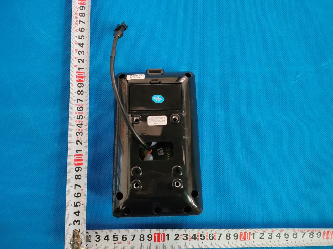
2BCJ8-S70
Sep 05, 2023Exercise bike
Equipment Class
DTS - Digital Transmission System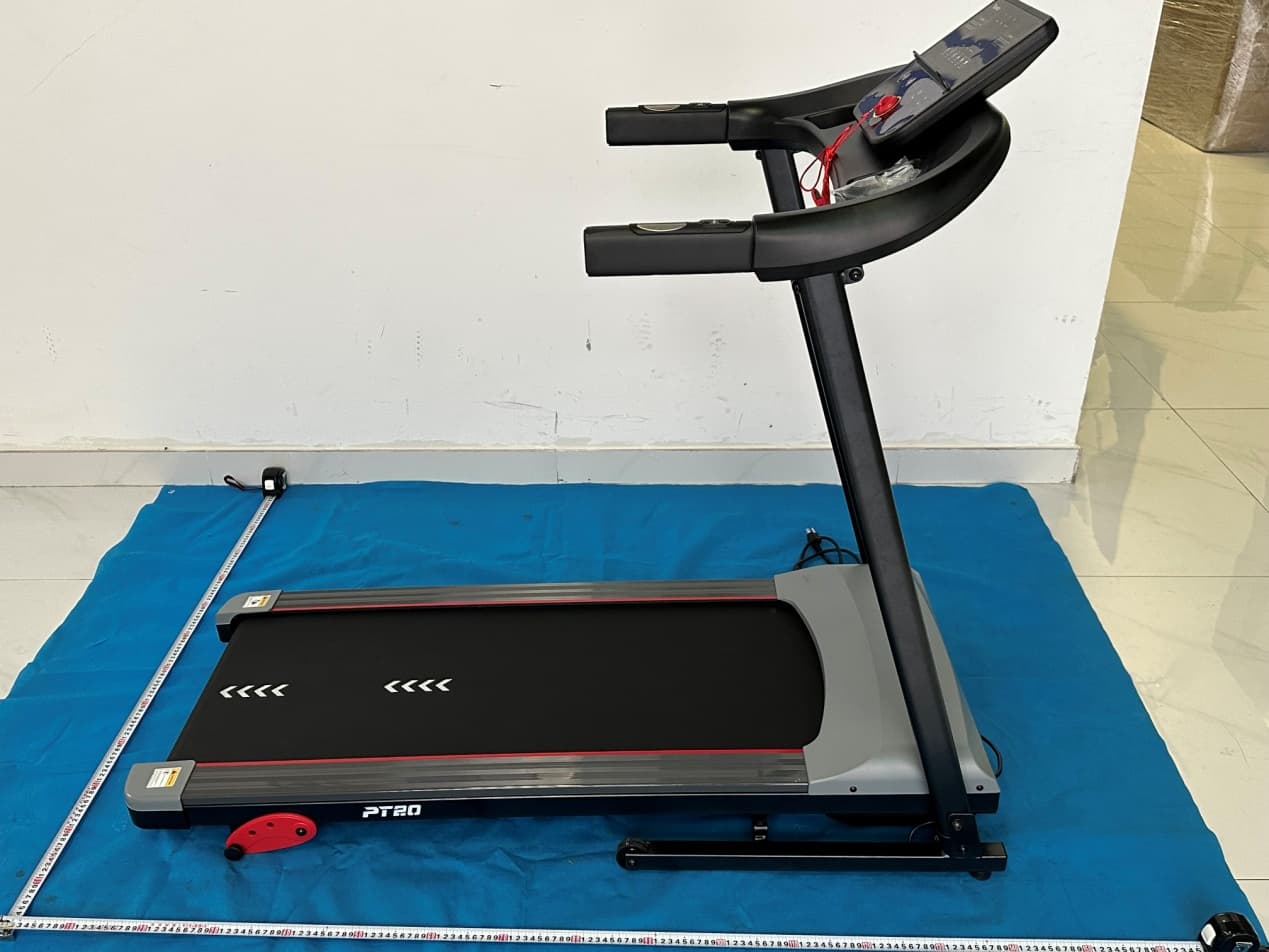
2BCJ8-PT20
Sep 04, 2023Treadmill
Equipment Class
DTS - Digital Transmission System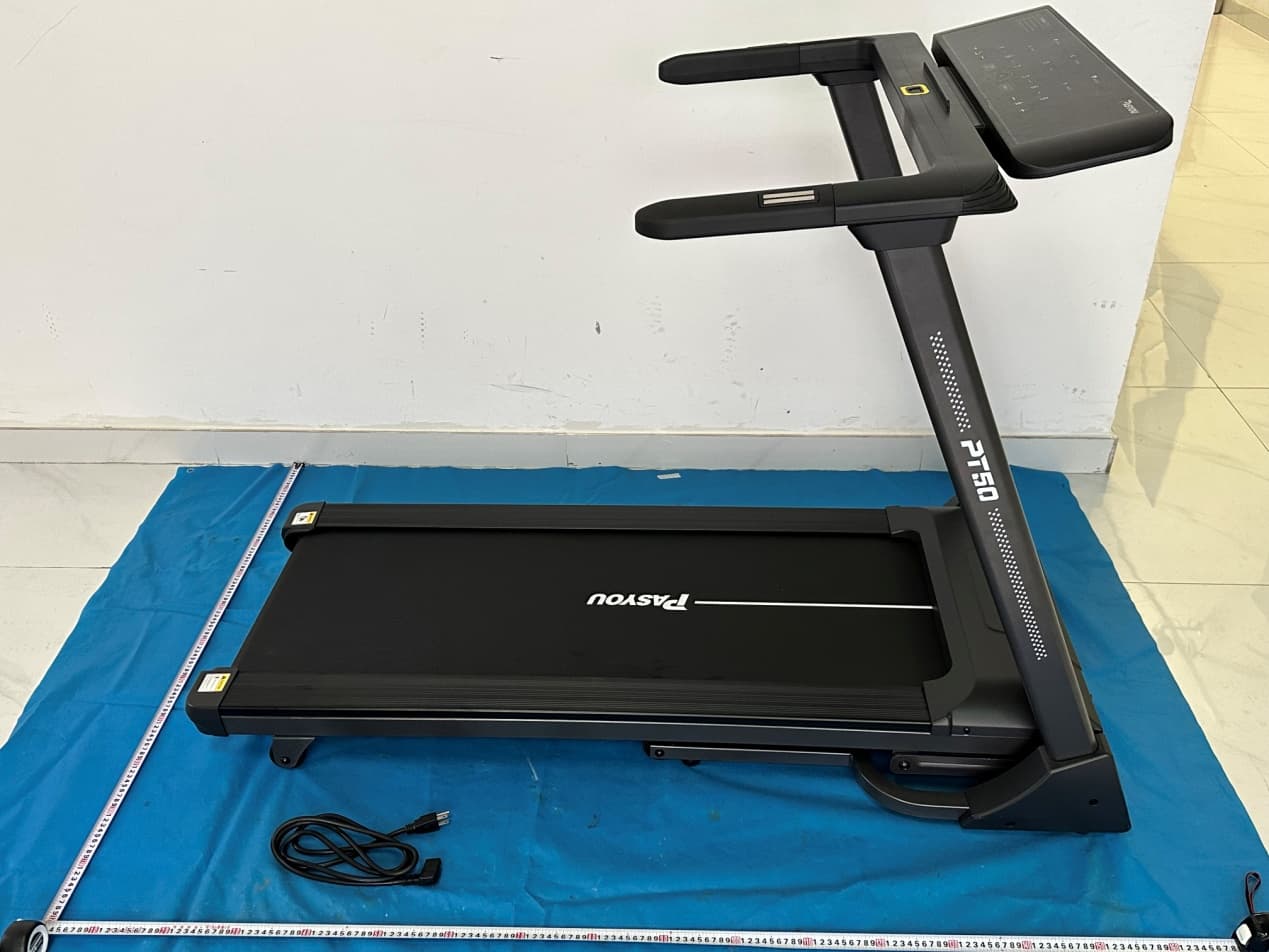
2BCJ8-PT50
Aug 26, 2023Treadmill
Equipment Class
DTS - Digital Transmission System