2BCPM-ATLATR200Atlas Radio Module
Atlas Aerospace SIA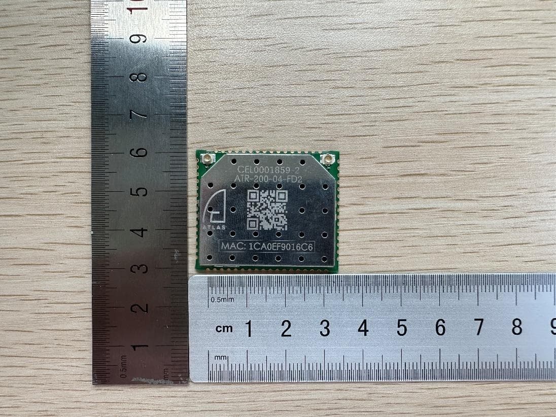
Click to zoom
Application Details
- Equipment Class
- DTS - Digital Transmission System
- Date of Grant
- Mar 07, 2024
- Application Purpose
- Original Equipment
- Date of Application
- Mar 07, 2024
- Equipment Note
- Atlas Radio Module
- Frequency Range
- 2412.00000000 - 2462.00000000
- Company
- Atlas Aerospace SIA
- Country
- Latvia
Documents & Files
Document Text
Text extracted from the exhibit documents filed with the FCC. Open a document above to read the original.
Users Manual
ATR200FD2 Atlas Aerospace 2 OVERVIEW The ATR-200 is a full-featured radio router in a small (37x31mm) castellated holes solderable form factor (aka OEM). The radio module is available for 2.4GHz frequency ranges and has a configurable output power of up to 22dBm per channel. It has 2 ethernet ports, 1 USB FS port that can be used to add any kind of additional peripherals, SPI and PCI-E port, as well as 10 GPIO. The different kinds of pre-designed carrier boards are available upon request. Key features Frequency hopping - 10 hops per second (under EUA) 2412-2462 MHz (20MHz bandwidth), 2405-2469 MHz (5MHz bandwidth) Low power consumption - 11 W @ full throttle (2x1W, max throughput) Configurable channel width - 5, 20MHz Configurable output power – up to 22dBm Automatically adjustable or fixed type of modulation - BPSK, QPSK, QAM16 ... QAM64 Communication ports - USB, 2x100 Mbit Ethernet ports, SPI, PCIe, GPIO Onboard Ethernet switch to support bridging and gateway configurations. Supports 802.11 standard roles- AP/Station or mesh (802.11s) Open platform to extend functionality with your own software services. Over radio updatable firmware. Security enhancement - WPA3 Personal (SAE) Industrial temperature range - 40°C ... +85°C Atlas Aerospace 3 Technical specification Frequency range 2.4 GHz Maximum output power 158mW (22dBm) configurable in 1dBm step Modulations BPSK...QAM64 Adaptive bitrate selection algorithm or fixed selection. Max. throughput (2 spatial streams) 5MHz, 20MHz 36Mbit/sec 72Mbit/sec 144Mbit/se c Antenna Connection *Reference Antenna UFL (Antenna port 0 (left) is used for TX/RX, Antenna port 1 (right) is only for RX, no TX function, only MISO Mode support. CIROCOMM FSAJ0I22 (2.4G Peak Gain:1.52dBi) Interfaces USB FS (12Mbit/s) 2x100Mbit ETH SPI PCIe UART(system console) Supply voltage +3.3V digital (2A max peak), +5V RF (2.5A max peak) POWER CONSUMPTION Max (10Mb/sec @QAM64) Typical (1Mb/sec @QAM16) Idle 11W (external heatsink required) 2-3W 1.5W ENVIRONMENTAL Temperature Humidity -40C - +85C 5-95% DIMENSIONS OEM AtlasPRO drone carrier board 31x37x4m m 43x72x8mm WEIGHT OEM AtlasPro Drone carrier board ~7g ~26g (w/o heatsink) Atlas Aerospace 4 Typical troughput Here are the experimental achieved throughput for a single channel configuration. Obtained by iperf3, UDP traffic. 1460 bytes packets. Single channel, 5MHz bandwidth. MCS level Throughput (Mbps) -50dB Throughput (Mbps) -85dB Throughput (Mbps) -88dB 0 (BPSK) 1.49 1.48 1.49 1 (QPSK) 2.99 2.98 2.98 2 (QPSK) 4.47 4.51 4.49 3 (QAM16) 6.04 5.99 5.91 4 (QAM16) 8.93 8.89 8.83 5 (QAM64) 10.9 - - 6 (QAM64) 11.6 - - 7 (QAM64) 14.4 - - Increasing channel’s bandwidth to 20 MHz will increase max throughtput almost linear up to 4 times correspondingly. Atlas Aerospace 5 Software and configuration The module running under Open Wrt Linux operating system and can be configured through the standard Linux interfaces - serial console over UART interface, SSH session on any of net- work interface including wireless interface, RPCD, Web, etc. Addition Open Wrt services such as socat, ser2net, FTP, SFTP, QoS, DNS, HTTPS, ICMP, NTP, DHCP, VLAN and much more can be installed as add-ons. Please check Open Wrt v19.07 for details about available packages. The software can be updated over the air. ATR-200 integration The radio module supplied in OEM form factor needs to be integrated into the carrier system. The carrier system has to provide power supply and connection to the module's interfaces. Maximum power consumption of the module is ~11W (1-2W for CPU, ~9W for RF). The recom- mended carrier system needs to be able to provide at least 2.5A for +5V RF rail. Digital +3.3V rail consumption is less than 2W for typical software packages, but it can be more depending on customer installed packages. During the integration a special care needs to be taken to guarantee thermal characteristics. In a best case scenario a carrier system or a UAV’s frame should be used as a heatsink. In some cases the external active cooling can be considered as an option. For digital peripheral connection the USB Full speed is provided on the module. Accordingly, if a carrier system requires, for instance, UART, I2C or I2S interfaces, then corresponding USB converters need to be integrated as well. Several USB converters can be connected using a trivial USB FS hub. For high speed data transmission the module provides 2x ETH ports that can be used in trans- former less mode as well as in classic configuration with transformers (aka ethernet magnet- ics). For easier integration and debugging it is recommended to add the ATR-200FD2 console port which is standard 115200 8N1 UART port. It should be considered that UART interface sup- poses high level of activity on TX pin, thus corresponding measures should be taken to avoid powering the module through the UART RX pin I.e. optical decoupling or additional MOSFET on console port. Atlas Aerospace 6 As an example, please find ATR-200 integration for AtlasPro UAV: The carrier board above has 2x100 Mbit/sec transformer less ethernet interfaces, one high speed UART port (up to 1 Mbit/s) to connect to AtlasPRO UAV autopilot, one I2 C temperature sensor connected via USB IO extender (based on STM32 MCU), one GPIO button for radio modules pairing, one serial console for debugging purposes and single input power connector. IO extender is a composite USB device with two interfaces: HID (for temperature sensor, leds and active cooling control) and ACM for high speed UART. The heatsink must be calculated for a particular design according to environmental character- istics, expected power consumption and requirements. Atlas Aerospace 7 INFORMAT ION TO USER This device complies with part 15 of the FCC Rules. Operation is subject to the following two conditions: (1) This device may not cause harmful interference, and (2) this device must accept any interference received, including interference that may cause undesired operation. This equipm…
Text truncated - open the document above for the full version.
Attestation Statements
12.19 341 3408
Attestation Statements
Atlas Aerospace SIA Attestation Statements Not Covered Entity Applicant To: Federal Communications Commission Date: 2023.10.31 7435 Oakland Mills Road, Columbia, MD 21046, USA Ref: Information Required by Section 2.911(d)(5)(ii) filing FCC ID: 2BCPM-ATLATR200 Atlas Aerospace SIA (“the applicant”) certifies that, as of the date of the filing of the application, the applicant is not identified on the Covered List (as a specifically named entity or any of its subsidiaries or affiliates) as an entity producing “covered” equipment. Sincerely yours, Applicant Signature Printed Name: Arturs Neitals Title: Chief Design Officer Address: Ulbrokas iela 19a, Riga, LV-1021, Latvia Te l . : +37129778900 Email: [email protected]
Cover Letter(s)
Atlas Aerospace SIA Authority to Act as Agent Date: 2023.10.31 TUV Rheinland of North America, Inc. 1279 Quarry Lane., Suite. A Pleasanton, CA 94566 To Whom It May Concern: I appoint TÜV Rheinland (Shenzhen) Co., Ltd. to act as our agent in the preparation of this application for equipment certification. I certify that submitted documents properly describe the device or system for which equipment certification is sought. I also certify that each unit manufactured, imported or marketed, as defined in the FCC or Industry Canada’s regulations will have affixed to it a label identical to that submitted for approval with this application. For instances where our authorized agent signs the application for certification on our behalf, I acknowledge that all responsibility for complying with the terms and conditions for Certification, as specified by TUV Rheinland Group, still resides with Atlas Aerospace SIA (address: Ulbrokas iela 19a, Riga, LV-1021, Latvia). For TCB applications, We certify that we are not subject to denial of federal benefits, that includes FCC benefits, pursuant to Section 5301 of the Anti-Drug Abuse Act of 1988, 21 U.S.C. 862. Further, no party, as defined in 47 CFR 1.2002 (b), to the application is subject to denial of federal benefits, that includes FCC benefits. Thank you, Agency Agreement Date: 2023.10.31 Agreement is valid for 12 months from the above date. By: __________________________ Arturs Neitals (Signature) (Print name) Chief Design Officer +37129778900 (Title) (Telephone) On behalf of: Atlas Aerospace SIA (Company Name) Page of 11
Cover Letter(s)
SPEC NO. SP03AC24508-0141 ISSUED DATE 2020.02.05 PUBLISHED BY PRODUCT NAME FSAJ0I22 VERSION 01 PAGE 1/5 2012.06.26 B400-010.05 This document is held by Cirocomm, cannot be reproduced without permission . SPECIFICATION SPEC NO. : SP03AC24508-0141 PART NO. : 03C15C030E0D10T PRODUCT NAME : FSAJ0I22 DESCRIPTION : FR4 Single-Band Antenna RoHS REVISION STATUS VERSION DATE PAGE REVISION DESCRIPTION PREPARED CHECKED APPROVED 01 2020.02.05 Whole New Issued. 翁秀惠 呂秉群 張敦信、吳佳宗 Prepared By Checked By Approved By SPEC NO. SP03AC24508-0141 ISSUED DATE 2020.02.05 PUBLISHED BY PRODUCT NAME FSAJ0I22 VERSION 01 PAGE 2/5 This document is held by Cirocomm, cannot be reproduced without permission . CIROCOMM TECHNOLOGY CORP. No.37 Industrial South Road,Kuntien Industrial Park Kuntien Hsiang,Tainan City, TAIWAN 72046 Tel: 886-6-6992961 PART NUMBER : 03C15C030E0D10T 1 SCOPE CIROCOMM’s customized FR4 Single-Band Antenna covers for WIFI Band. 2 Name of the product This product is named “FR4 Single-Band Antenna “. 3 Electrical characteristics 3-1 Electrical characteristics of antenna The antenna has the electrical characteristics given in Table 1 under the CIROCOMM standard installation conditions shown in the figure of Evaluation Board. Table 1 No Parameter Specification 1 Working Frequency 2400-2500 MHz 2 Dimension 47.8*12.45*1 mm 3 Polarization Linear 4 Operating Temperature -40°C to +85°C * Actual value will depend on customer ground plane size. WIFI Antenna Peak Gain SPEC NO. SP03AC24508-0141 ISSUED DATE 2020.02.05 PUBLISHED BY PRODUCT NAME FSAJ0I22 VERSION 01 PAGE 3/5 This document is held by Cirocomm, cannot be reproduced without permission . WIFI Antenna Average Gain Frequency (MHz) 2400 2450 2500 Peak Gain (dBi) 1.65 1.52 1.86 Average Gain (dBi) -1.81-1.79-1.91 3D Radiation Pattern SPEC NO. SP03AC24508-0141 ISSUED DATE 2020.02.05 PUBLISHED BY PRODUCT NAME FSAJ0I22 VERSION 01 PAGE 4/5 This document is held by Cirocomm, cannot be reproduced without permission . 4 Environmental conditions 4-1 Operating conditions The antenna has the electrical characteristics given in Tables 1 in the temperature range of -40°C to +85°C and under the environmental conditions of +40°C and 0-95﹪r.h.. 4-2 Storage temperature range The storage temperature range of product is -40°C to +85°C 5 Reliability tests The decision standard of the confirmation of the movement is doing the characteristic electric standard of the antenna module. And, the decision standard of the appearance isn’t thought function problem become defect be. 5-1 Low-temperature test Expose the specimen to -40°C for 16 hours and then to normal temperature/ humidity for 24 hours or more. After that examine the appearance and functions. 5-2 High-temperature test Expose the specimen to +85°C for 16 hours and then to normal temperature/ humidity for 24 hours or more. After that examine the appearance and functions. 6 Inspection As for the examination in the mass production, the receiving character of the ratio wave sent in a shield box from the standard antenna and VSWR are confirmed in the picking out examination. 7 Warranty If any defect occurs form the product during proper use within a year after delivery, it will be repaired or replaced free of charge. 8 Other Any question arising from this specification manual shall be solved by arrangement made by both parties. 9 Drawings ANTENNA
Cover Letter(s)
Atlas Aerospace SIA Date: 2023.10.31 Federal Communica<ons Commission Equipment Authoriza<on Branch 7435 Oakland Mills Road, Columbia, MD 21046, USA Subject: Confiden<ality Request for FCC ID: 2BCPM-ATLATR200 Pursuant to FCC 47 CRF 0.457(d), the applicant requests that a part of the subject FCC/IC applica<on be held confiden<al. Atlas Aerospace SIA has spent substan<al e ffort in developing this product and it is one of the first of its kind in industry. Having the subject informa<on easily available to "compe<<on" would negate the advantage they have achieved by developing this product. Not protec<ng the details of the design will result in financial hardship. Permanent Confiden-ality: The applicant requests the exhibits listed above as permanently confiden<al be permanently withheld from public review due to materials that contain trade secrets and proprietary informa<on not customarily released to the public. (*** Excep<onal case for Permanent Confiden<ality for these Exhibits by PAG only) Short-Term Confiden-ality: The applicant requests the exhibits selected above as short term confiden<al be withheld from public view for a period of N/A days from the date of the Grant of Equipment Authoriza<on and prior to marke<ng. This is to avoid premature release of sensi<ve informa<on prior to marke<ng or release of the product to the public. Applicant is also aware that they are responsible to no<fy TUV Rheinland in the event informa<on regarding the product or the product is made available to the public. TUV Rheinland will then release the documents listed above for public disclosure pursuant to FCC Public No<ce DA 04-1705. Sincerely, By: __________________Chief Design Officer____ _____________ Arturs Neitals _______________ (Signature/Title) (Print name) Tel: +37129778900 Email: cer<fica<[email protected] Type of Confiden-ality RequestedExhibit Short Term Permanent √Block Diagrams Short Term n/aExternal Photo Short Term PermanentInternal Photos *** Short Term Permanent √Opera<on Descrip<on/Theory of Opera<on Short Term Permanent √Schema<cs Short Term PermanentTest Setup*** Short Term PermanentTune-Up Procedure Short Term PermanentUser’s Manual*** Short Term Permanent √Part List/ Antenna Construc<on MS-0044715 Page of Revision 111
Cover Letter(s)
Declaration The product: Atlas Radio Module (Model No.: ATR-200) only supports MISO mode, and only one antenna port can be used for transmission. __________________________ (Signature) Con tact Person: Arturs Neitals Company: Atlas Aerospace SIA
Cover Letter(s)
Modular Approval Request FCC FCC ID: 2BCPM-ATLATR200 Items to be covered Answer from applicant 1.The modular transmitter must have its own RF shielding.YES , please refer to EUT photo 2.The modular transmitter must have buffered modulation/data inputs (if such inputs are provided) to ensure that the module will comply with Part 15 requirements under conditions of excessive data rates or over-modulation. All modulation and data input(s) are buffered. The EUT h as buffered data inputs, it is integrated on chip QCA4531 3.The modular transmitter must have its own power supply regulation. Module has its own power regulator. 4.The modular transmitter must comply with the antenna requirements of Section 15.203 and 15.204(c). The antenna must either be permanently attached or employ a “unique” antenna coupler (at all connections between the module and the antenna, including the cable).. The mo dular transmitter uses a ‘unique’ antenna connector in form of two u.FL connectors. 5.The modular transmitter must be tested in a stand-alone configuration, i.e., the module must not be inside another device during testing. This is intended to demonstrate that the module is capable of complying with Part 15 emission lim its regardless of the device into which it is eventually installed. YES , please refer to test photo 6.The modular transmitter must be labeled with its own FCC ID number, and, if the FCC ID is not visible when the module is installed inside another device, then the outside of the device into which the module is installed must also display a label referring to the enclosed module. This exterior label can use wording such as the following: “Contains Transmitter Module FCC ID: XYZMODEL1” or “Contains FCC ID: XYZMODEL1 .” Any similar wording that expresses the same meaning may be used. The Grantee may either provide such a label, an example of which must be included in the application for equipment authorization, or, must provide adequate instructions along with the module which explain this requirement. In th e latter case, a copy of these instructions must be included in the application for equipment authorization. YES , please refer to label 7.The modular transmitter must comply with any specific rule or operating requirements applicable to the transmitter and the manufacturer must provide adequate instructions along with the module to explain any such requirements. A copy of these instructions must be included in the application for equipment authorization. For example, there are very strict operational and timing requirements that must be met before a transmitter is authorized for operation unde r Section 15.231. For instance, data transmission is prohibited, except for operation under Section 15.231(e), in which case there are separate field strength level and timing requirements. Compliance with these requirements must be assured. YES , please refer to User manual 8.The modular transmitter must comply with any applicable RF exposure requirements. For example, FCC Rules in Sections 2.1091, 2.1093 and specific Sections of Part 15, including 15.319(i), 15.407(f), 15.253(f) and 15.255(g), require that Unlicensed PCS, UNII and millimeter wave devices perform routine environmental evaluation for RF Exposure to demonstrate compliance. In ad dition, spread spectrum transmitters operating under Section 15.247 are required to address RF Exposure compliance in accordance with Section 15.247(b)(4). Modular transmitters approved under other Sections of Part 15, when necessary, may also need to address certain RF Exposure concerns, typically by providing specific installation and operating instructions for users, installers and other interested parties to ensure compliance. Yes, Please refer the Maximum Permissible Exposure Information Note: If compliance with one or more of the numbered requirements, listed above, cannot be demonstrated, it may be possible to obtain a “Limited Modular Approval” (LMA). Name and surname of applicant (or authorized representative): Arturs Neitals/CDO Date: 2023-10-18 S ignature:
External Photos
Document No: SHE23100021-01 Page 1 of 1 External photo Front Rear
Internal Photos
Document No: SHE23100021-01 Page 1 of 2 Internal photo Internal 1 Antenna photo Document No: SHE23100021-01 Page 2 of 2 Antenna photo-Front Antenna photo-Back
RF Exposure Info
RFEXPOSURETESTREPORT ReportNo.:SHE23100021-01CERDate:2023-10-24 Page 1 of 7 Applicant:AtlasAerospaceSIA AddressofApplicant:UlbrokasStreet19A,1021Riga,Latvia ProductName:AtlasRadioModule BrandName:ATLAS ModelName:ATR-200 SampleAcquisitionMethod:SentbyClient SampleNo.:E23100021-01#02 FCCID:2BCPM-ATLATR200 Standard:FCCPart2.1093 DateofReceipt:2023-10-11 DateofTest:2023-10-11~2023-10-18 DateofIssue:2023-10-24 Remark: Thisreportdetailstheresultsofthetestingcarriedoutononesample,theresultscontainedinthisreportdonotrelate toothersamplesofthesameproduct.Themanufacturershouldensurethatallproductsinseriesproductionarein conformitywiththeproductsampledetailedinthisreport. Preparedby:Reviewedby:Approvedby: (ErikYang)(JenniferZhou)(Authorizedsignatory:EchoMu) RFEXPOSURETESTREPORT ReportNo.:SHE23100021-01CERDate:2023-10-24 Page 2 of 7 Contents 1GENERALINFORMATION.....................................................................................................................................................3 1.1TESTINGLABORATORY................................................................................................................................................................3 1.2DETAILSOFAPPLICATION...........................................................................................................................................................3 1.3DETAILSOFEUT.........................................................................................................................................................................3 2ASSESSMENTMETHODS.....................................................................................................................................................4 3CONCLUSION...........................................................................................................................................................................5 4APPENDIXES............................................................................................................................................................................6 4.1SAMPLEPHOTOGRAPH................................................................................................................................................................6 RFEXPOSURETESTREPORT ReportNo.:SHE23100021-01CERDate:2023-10-24 Page 3 of 7 1GeneralInformation 1.1TestingLaboratory CompanyNameICASTestingTechnologyService(Shanghai)Co.,Ltd. AddressNo.1298,PinganRoad,MinhangDistrict,Shanghai,China Telephone008621-51682999 Fax008621-54711112 Homepagewww.icasiso.com 1.2DetailsofApplication ApplicantCompanyNameAtlasAerospaceSIA AddressUlbrokasStreet19A,1021Riga,Latvia ContactPersonArtursNeitals Telephone+37129778900 [email protected] ManufacturerCompanyNameAtlasAerospaceSIA AddressUlbrokasStreet19A,1021Riga,Latvia 1.3DetailsofEUT ProductNameAtlasRadioModule BrandNameATLAS TestModelNameATR-200 FCCID2BCPM-ATLATR200 FrequencyRange2405MHz~2469MHz ModulationTypeOFDM RFOutputPower Bandwidth5M:20.67dBm Bandwidth20M:21.28dBm AntennaTypeExternalAntenna AntennaGain1.52dBi HardwareVersionATR-200-04-FD2 SoftwareVersionr0+13092-74da93979e RFEXPOSURETESTREPORT ReportNo.:SHE23100021-01CERDate:2023-10-24 Page 4 of 7 2Assessmentmethods AccordingtoKDB447498D04InterimGeneralRFExposureGuidancev01 AppendixB ExemptionsforSingleRFSources SAR-basedthresholdsarederivedbasedonfrequency,power,andseparationdistanceoftheRFsource.Theformula definesthethresholdsingeneralforeitheravailablemaximumtime-averagedpowerormaximumtime-averagedERP, whicheverisgreater. IftheERPofadeviceisnoteasilydetermined,suchasforaportabledevicewithasmallformfactor,theapplicantmay usetheavailablemaximumtime-averagedpowerexclusivelyifthedeviceantennaorradiatingstructuredoesnot exceedanelectricallengthofλ/4. Asfordeviceswithantennasoflengthgreaterthanλ/4wherethegainisnotwelldefined,butalwayslessthanthatofa half-wavedipole(lengthλ/2),theavailablemaximumtime-averagedpowergeneratedbythedevicemaybeusedin placeofthemaximumtime-averagedERP,wherethatvalueisnotknown. Theseparationdistanceisthesmallestdistancefromanypartoftheantennaorradiatingstructureforallpersons, duringoperationattheapplicableERP.Inthecaseofmobileorportabledevices,theseparationdistanceisfromthe outerhousingofthedevicewhereitisclosesttotheantenna. TheSAR-basedexemptionformulaof§1.1307(b)(3)(i)(B),repeatedhereasFormula(B.2),appliesforsinglefixed, mobile,andportableRFsourceswithavailablemaximumtime-averagedpoweroreffectiveradiatedpower(ERP), whicheverisgreater,oflessthanorequaltothethresholdPth(mW). Thismethodshallonlybeusedatseparationdistancesfrom0.5cmto40cmandatfrequenciesfrom0.3GHzto6 GHz(inclusive).PthisgivenbyFormula(B.2). andfisinGHz,distheseparationdistance(cm),andERP20cmisperFormula(B.1). TheexamplevaluesshowninTableB.2areforillustrationonly. RFEXPOSURETESTREPORT ReportNo.:SHE23100021-01CERDate:2023-10-24 Page 5 of 7 3Conclusion PerKDB447498D04InterimGeneralRFExposureGuidancev01AppendixB, whentheminimumtestseparationdistanceis40mm,adistanceof40mmisappliedtodetermineSARtestexclusion. Thetestexclusionthresholdis<143mW. RFMaximumOutputPower: Bandwidth5M:20.67dBm Bandwidth20M:21.28dBm ERP: Bandwidth5M:20.04dBm(100.93mW)<143mW Bandwidth20M:20.65dBm(116.14mW)<143mW SoSARtestingisnotrequired.RFexposureEvaluationResults:Compliance RFEXPOSURETESTREPORT ReportNo.:SHE23100021-01CERDate:2023-10-24 Page 6 of 7 4Appendixes 4.1SamplePhotograph Frontofthesample Rearofthesample ***Endofthereport*** RFEXPOSURETESTREPORT ReportNo.:SHE23100021-01CERDate:2023-10-24 Page 7 of 7
Test Report
TESTREPORT ReportNo.:SHE23100021-01AEDate:2023-10-24 Page 1 of 69 Applicant:AtlasAerospaceSIA AddressofApplicant:UlbrokasStreet19A,1021Riga,Latvia ProductName:AtlasRadioModule BrandName ModelName : : ATLAS ATR-200 SampleAcquisitionMethod:SentbyClient SampleNo. FCCID : : E23100021-01#02 2BCPM-ATLATR200 Standards:FCCCFR47Part15,SubpartC DateofReceipt:2023-10-11 DateofTest:2023-10-11~2023-10-18 DateofIssue:2023-10-24 Remark: Thisreportdetailstheresultsofthetestingcarriedoutononesample,theresultscontainedinthisreportdonotrelate toothersamplesofthesameproduct.Themanufacturershouldensurethatallproductsinseriesproductionarein conformitywiththeproductsampledetailedinthisreport. Preparedby:Reviewedby:Approvedby: (ErikYang)(JenniferZhou)(Authorizedsignatory:EchoMu) TESTREPORT ReportNo.:SHE23100021-01AEDate:2023-10-24 Page 2 of 69 Contents 1GENERALINFORMATION.....................................................................................................................................................3 1.1TESTINGLABORATORY................................................................................................................................................................3 1.2DETAILSOFAPPLICATION...........................................................................................................................................................3 1.3DETAILSOFEUT.........................................................................................................................................................................3 1.4TESTMETHODOLOGY..................................................................................................................................................................4 1.5TESTSUMMARY...........................................................................................................................................................................5 2TESTCONDITION....................................................................................................................................................................6 2.1ENVIRONMENTALCONDITIONS....................................................................................................................................................6 2.2EQUIPMENTLIST..........................................................................................................................................................................6 2.3MEASUREMENTUNCERTAINTY....................................................................................................................................................6 3TESTSET-UPANDOPERATIONMODES.........................................................................................................................7 3.1DETAILSOFTESTMODE.............................................................................................................................................................7 3.2SPECIALACCESSORIESANDAUXILIARYEQUIPMENT................................................................................................................7 3.3SUPPORTSOFTWARE..................................................................................................................................................................7 3.4TESTSETUPDIAGRAM................................................................................................................................................................8 4TESTRESULTS........................................................................................................................................................................9 4.1TRANSMITTERREQUIREMENT&TESTSUITES..........................................................................................................................9 4.1.1AntennaRequirement.........................................................................................................................................................9 4.1.2Maximumpeakconductedoutputpower.......................................................................................................................10 4.1.36dBBandwidth...................................................................................................................................................................11 4.1.4Maximumconductedoutputpowerspectraldensity....................................................................................................15 4.1.5ConductedSpuriousEmission&Authorized-bandband-edge..................................................................................19 4.1.6RadiatedEmission............................................................................................................................................................31 4.1.7BandEdge(Restricted-bandband-edge)......................................................................................................................58 5APPENDIXES..........................................................................................................................................................................66 5.1PHOTOGRAPHSOFTHESAMPLE...............................................................................................................................................66 5.2SET-UPFORCONDUCTEDRFTESTATANTENNAPORT.........................................................................................................67 5.3SET-UPFORSPURIOUSEMISSIONSBELOW1GHZ..................................................................................................................67 5.4SET-UPFORSPURIOUSEMISSIONSABOVE1GHZ..................................................................................................................68 TESTREPORT ReportNo.:SHE23100021-01AEDate:2023-10-24 Page 3 of 69 1GeneralInformation 1.1TestingLaboratory CompanyNameICASTestingTechnologyS…
Text truncated - open the document above for the full version.
Contact Information
Applicant
Arturs Neitals
Technical Contact
Test Firm
ICAS Testing Technology Service (Shanghai) Co, LtdZhenyang Zhang
[email protected]086 021516829997864
Technical Specifications
| # | Rule Parts | Frequency Range | Power Output |
|---|---|---|---|
| 2 | 15C | 2.41 GHz - 2.46 GHz | 134.30 mW |