2BCUQ-W710DDECT IP Base Station
Fanvil Link Technology Co.,LTD
Click to zoom
Application Details
- Equipment Class
- PUB - Part 15 Unlicensed PCS Base Station
- Date of Grant
- Jun 26, 2024
- Application Purpose
- Original Equipment
- Date of Application
- Jun 25, 2024
- Equipment Note
- DECT IP Base Station
- Frequency Range
- 1921.53600000 - 1928.44800000
- Country
- China
Documents & Files
Document Text
Text extracted from the exhibit documents filed with the FCC. Open a document above to read the original.
Users Manual
W710D Quick Installation Guide V1.0 DECT base station Power Adapter(optional) Pack aging Panel list QuickInst allation Guide TA4*30mm Screw*2 Screw Fixing Seat*2 PA3*8mm Screw*1 DECT LED WAN LED ROLE LED Reset Key Status indicator Lights indicator DescriptionFunction Indicates the WAN connection status Indicates the device role On: Device works as Manager Indicates the status of system On: Successfully connected to the local area network OffNo network cable inserted Flash: Network anomalies such as IP conflict or failure to obtain IP DC 5V IN WAN LAN Function Connecting to a power source to the DC Jack. Connecting to the network. Connecting to the IP Phone. Interface Power Network Ports Deviceports DC 5V INWANLAN Flash: There are active calls in the system WAN LED ROLE LED DECT LED Device connection Step 1: Prepare before installation 1. Voltage check Check whether the voltage of DC power supply or external power supply is within the working range of this product (5V/1A). 2. Adjust the antenna (Figure 1) Press the heads of the antennas at both ends of the device (marked with red lines) with slightly, the antennas will automatically pop out, and then rotate the two antennas clockwise to the desired angle (the maximum rotatable angle is 190°). 3. Open the back cover (Figure 2) Follow the arrows to slide down to open the back cover. Figure 1-bFigure 1-cFigure 1-a Figure 2-aFigure 2-bFigure 2-c Step 2: Connect your device, please follow the steps below: 1. Insert the ethernet cable into the WAN port of the device and connect the other end of the ethernet cable to an uplink port (a router or a modem, etc.) 2. Insert the power adapter into the device and connect it to a wall outlet. 3. The WAN LED will be solidly lit when the device and network is ready for use. Step 3: Wall mounting 1. Close the back cover of the device after plugging in the cable, and punch the PA3*8mm Screw into the hole in the back cover (Figure 3) Obtaining the IP address Obtain the IP address through the scanning tool 1. Download the scanning tool: Go to Fanvil's official website in a web browser, select Support > Download Center > Tools > IPScanner, Select DeviceManager Latest version and download. 2. Open the IP scanning tool, click Rescan, search and find the IP address of your device. Add a terminal Device management Device management 1. Enter the IP address of your device in your browser. 2. Navigate to the Manager webpage > Handset > Maintenance, Click Add and config Device IPUI, Name, and Authorized To Access to add the terminal. 3. Then the terminal can connect to the Manager. Once the terminal successfully connects to the Manager, administrators can perform information management and operations on the terminal in the "W710D-Manager" >> "Handest" page, including: 1.Terminal Information Viewing: Administrators can view the terminal's online status, IPUI, extension number, SIP account, name, model, software version, and the current connected Base. 2.Operate the terminal Administrators can perform operations such as rebooting, upgrading, managing configurations, and managing SIP accounts on the terminal. Figure 3 2. Wall mounting can be achieved by hanging the equipment on a screw suitable for the size and distance of the two holes above and below the back shell Add SIP Account 1.SIP Account Management: Administrators can perform operations such as adding/ deleting/editing SIP accounts for the terminal. Specific operations are as follows: 1.1 Adding SIP Server: Access the W710D Manager web page "SIP Account " >> "SIP Server" click to add a SIP server. Input the registration address, domain name, and registration port provided by the SIP server administrator. 1.2 Adding SIP Account: 1.2.1 Manually Adding a Single SIP Account: Access the W710D Manager web page >> "SIP Account Management" >> "SIP Account," click to add. Manually fill in the SIP account information: registration username, registration password, SIP user, display name, etc.,provided by the SIP server administrator. 1.2.2 Bulk Import of SIP Accounts: Access the W710D Manager webpage "SIP Account" >> "SIP Accounts, " click "Export" to export the template. After editing the template to add SIP accounts, click "Import" to import the SIP account list. Please note that the imported template must be in UTF-8 encoding Factory data reset Restore factory Settings by pressing keysLong press the Reset button for about 10 seconds, and the device will automatically restore factory Settings. Any Changes or modifications not expressly approved by the party responsible for compliance could void the user's authority to operate the equipment. This device complies with part 15 of the FCC Rules. Operation is subject to the following two conditions: (1) This device may not cause harmful interference, and (2) this device must accept any interference received, including interference that may cause undesired operation. Note: This equipment has been tested and found to comply with the limits for a Class B digital device, pursuant to part 15 of the FCC Rules. These limits are designed to provide reasonable protection against harmful interference in a residential installation. This equipment generates,uses and can radiate radio frequency energy and, if not installed and used in accordance with the instructions, may cause harmful interference to radio communications. However, there is no guarantee that interference will not occur in a particular installation. If this equipment does cause harmful interference to radio or television reception, which can be determined by turning the equipment off and on, the user is encouraged to try to correct the interference by one or more of the following measures: —Reorient or relocate the receiving antenna. —Increase the separation between the equipment and receiver. —Connect the equipment into an outlet on a circuit different from that to which the receiver is connected. —Consult the dealer or an experienced radio/TV technician for help. This de…
Text truncated - open the document above for the full version.
Attestation Statements
FanvilLinkTechnologyCo.,LTD A03,A08,3rdFloor,Building2,DaqianIndustrialPlant,Zone67,XingdongCommunity,Xin'anStreet, Bao'anDistrict,Shenzhen,China FederalCommunicationsCommission AuthorizationandEvaluationDivision 7435OaklandMillsRoad Columbia,MD21046 USA Date:Jun.14,2024 Ref:AttestationStatementsPart2.911(d)(5)(i)Filing FCCID:2BCUQ-W710D FRN:0034227223 [FanvilLinkTechnologyCo.,LTD](“theapplicant”)certifiesthattheequipmentforwhichauthorizationis soughtisnot“covered”equipmentprohibitedfromreceivinganequipmentauthorizationpursuantto section2.903oftheFCCrules. Sincerely, (Applicantsignature) (mengjiaoHu)
Attestation Statements
FanvilLinkTechnologyCo.,LTD A03,A08,3rdFloor,Building2,DaqianIndustrialPlant,Zone67,XingdongCommunity,Xin'an Street,Bao'anDistrict,Shenzhen,China FederalCommunicationsCommission AuthorizationandEvaluationDivision 7435OaklandMillsRoad Columbia,MD21046 USA Date:Jun.14,2024 Ref:AttestationStatementsPart2.911(d)(5)(ii)Filing FCCID:2BCUQ-W710D FRN:0034227223 [FanvilLinkTechnologyCo.,LTD](“theapplicant”)certifiesthat,asofthedateofthefilingofthe application,theapplicantisnotidentifiedontheCoveredListasanentityproducing“covered” equipment. Sincerely, (Applicantsignature) (mengjiaoHu)
Attestation Statements
FanvilLinkTechnologyCo.,LTD A03,A08,3rdFloor,Building2,DaqianIndustrialPlant,Zone67,XingdongCommunity,Xin'anStreet,Bao'an District,Shenzhen,China 2.911(d)(7)USAAgentv1.2 Section2.911(d)(7)USAAgentforServiceofProcess FCCID:2BCUQ-W710D 2.911(d)(7)USADesignatedAgentforServiceofProcess We,[FanvilLinkTechnologyCo.,LTD](“theapplicant”)designate[EMCTEK.] NOTE1 forthepurposeofacceptingserviceofprocessonbehalfof theapplicant. Applicantconsent:WeAcknowledgeourconsenttoacceptserviceofprocessintheUnitedStatesformattersrelatedtotheapplicable equipment,andatthephysicalU.S.addressandemailaddressofthedesignatedagentandacknowledgeouracceptanceofourobligationto maintainanagentforserviceofprocessintheUnitedStatesfornolessthanoneyearaftereitherthegranteehaspermanentlyterminatedall marketingandimportationoftheapplicableequipmentwithintheU.S.,ortheconclusionofanyCommission-relatedadministrativeorjudicial proceedinginvolvingtheequipment,whicheverislater. Agentobligation:WeAcknowledgeourobligationtoacceptserviceofprocessintheUnitedStatesformattersrelatedtotheapplicable equipmentatourphysicalU.S.addressandemailaddressfornolessthanoneyearaftereitherthegranteehaspermanentlyterminatedall marketingandimportationoftheapplicableequipmentwithintheU.S.,ortheconclusionofanyCommission-relatedadministrativeorjudicial proceedinginvolvingtheequipment,whicheverislater. USAAgent Companyname:EMCTEK Address:11788BigCanyonLn,SanDiegoCA92131USA FRN:00334018291 ContactName:FangLiu TelephoneNo:/ Email:[email protected] Applicant Companyname:FanvilLinkTechnologyCo.,LTD Address:A03,A08,3rdFloor,Building2,DaqianIndustrialPlant,Zone 67,XingdongCommunity,Xin'anStreet,Bao'anDistrict,Shenzhen, China FRN:0034227223 ContactName:MengjiaoHu TelephoneNo:15089240223 Email:[email protected] Signature: Date:2024.06.20Date:2024.06.20 NOTE1:AnapplicantlocatedintheUnitedStatesmaydesignateitselfastheagentforserviceofprocess. Reference;FederalRegisterdocument2022-28263publishedon02/06/23 https://www.federalregister.gov/documents/2023/02/06/2022-28263/protecting-against-national-security-threats-to-the-communications-supply-c hain-through-the
Cover Letter(s)
Fanvil Link Technology Co., LTD A03, A08, 3rd Floor, Building 2, Dagian IndustralPlant, Zone 67, Xingdong Community, Xin'anStreet, Bao'an District, Shenzhen , China Jun. 14, 2024 Office of Engineering Technology Federal Communications Commission 7435 Oakland Mills Road Columbia, MD 21046 USA Subject: Explanation of differences between product types FCC ID: 2BCUQ-W710D Models: W710D, W610DP, W710P, W610P To Whom It May Concern: We, The Fanvil Link Technology Co., LTD hereby declare that the model : W610DP, W710P,W610P is identical with the model : W710D, only the model names are different Sincerely, Fanvil Link Technology Co., LTD Signature: [mengjiao Hu, General Manager]
Cover Letter(s)
FanvilLinkTechnologyCo.,LTD A03,A08,3rdFloor,Building2,DaqianIndustrialPlant,Zone67,XingdongCommunity, Xin'anStreet,Bao'anDistrict,Shenzhen,China OfficeofEngineeringTechnology FederalCommunicationsCommission 7435OaklandMillsRoad Columbia,MD21046 USA Date:Jun.14,2024 Subject;RequestforConfidentiality FCCID:2BCUQ-W710D ToWhomItMayConcern, PursuanttotheprovisionsoftheCommission’srulesTitle47Sections§0.457and§0.459,we arerequestingtheCommissiontowithholdthefollowingattachment(s)asconfidential documentsfrompublicdisclosureindefinitely. Thesedocumentscontaindetailedsystemandequipmentdescriptionsandareconsideredas proprietaryinformationinoperationoftheequipment.Thepublicdisclosureofthesedocuments mightbeharmfultoourcompanyandwouldgivecompetitorsanunfairadvantageinthemarket. SchematicDiagram BlockDiagram OperationalDescription PartsList Inadditionaltoabovementioneddocuments,inordertocomplywiththemarketingregulations inTitle47CFR§2.803andtheimportationrulesinTitle47CFR§2.1204,whileensuringthat businesssensitiveinformationremainsconfidentialuntiltheactualmarketingofnewly authorizeddevices,werequestShortTermConfidentialityofthefollowingattachment(s); ExternalPhotos TestSetupPhotos InternalPhotos UserManual For45days,pursuanttoPublicNoticeDA04-1705. OR For180dayspursuanttoKDB726920D01. Itisourunderstandingthatallmeasurementtestreports,FCCIDlabelformatand correspondenceduringthecertificationreviewprocesscannotbegrantedasconfidential authorizationisissued. Sincerely, Signature: Name:mengjiaoHu Title:GeneralManager
Cover Letter(s)
Fanvil Link Technology Co., LTD A03, A08, 3rd Floor, Building 2, Daqian Industrial Plant, Zone 67, Xingdong Community, Xin'an Street, Bao'an District, Shenzhen, China (Jun. 14, 2024) Eurofins Electrical and Electronic Testing NA, Inc. 914 West Patapsco Avenue Baltimore, MD 21230 RE: LETTER OF AGENT AUTHORIZATION To Whom It May Concern: We, the undersigned, hereby authorize (Attestation of Global Compliance (Shenzhen) Co., Ltd) to act on our behalf in all matters relating to application for equipment authorization, including the signing of all documents relating to these matters. We also hereby certify that no party to the application authorized hereunder is subject to the denial of benefits, including FCC benefits, pursuant to Section 5301 of the Anti-Drug Abuse Act of 1988, 21 U.S.C.853(a). This agreement expires one year from the current date. Sincerely, Name: mengjiao Hu Title: General Manager
External Photos
Report No.: AGC14499240406AP02 Page 1 of 4 EXTERNAL PHOTOS WHOLE VIEW OF EUT TOP VIEW OF EUT Adapter 2#: F05L5-050100SPAU Adapter 1#: GQ07A-050100-DU Report No.: AGC14499240406AP02 Page 2 of 4 BOTTOM VIEW OF EUT FRONT VIEW OF EUT Report No.: AGC14499240406AP02 Page 3 of 4 BACK VIEW OF EUT LEFT VIEW OF EUT DECT Antenna Report No.: AGC14499240406AP02 Page 4 of 4 RIGHT VIEW OF EUT ****************************************End of Report*************************************
ID Label/Location Info
FCC ID Label Location 50mm*10mm FCC ID: 2BCUQ-W710D
Internal Photos
Report No.: AGC14499240406AP02 Page 1 of 7 INTERNAL PHOTOS OPEN VIEW-1 OF EUT OPEN VIEW-2 OF EUT Report No.: AGC14499240406AP02 Page 2 of 7 PORT OF EUT INTERNAL VIEW-1 OF EUT Report No.: AGC14499240406AP02 Page 3 of 7 INTERNAL VIEW-2 OF EUT ANTENNA OPEN OF EUT Report No.: AGC14499240406AP02 Page 4 of 7 DECT ANTENNA VIEW-1 OF EUT DECT ANTENNA VIEW-2 OF EUT Report No.: AGC14499240406AP02 Page 5 of 7 INTERNAL VIEW-3 OF EUT INTERNAL VIEW-4 OF EUT Report No.: AGC14499240406AP02 Page 6 of 7 INTERNAL VIEW-5 OF EUT INTERNAL VIEW-6 OF EUT Report No.: AGC14499240406AP02 Page 7 of 7 INTERNAL VIEW-7 OF EUT ****************************************End of Report*************************************
RF Exposure Info
Page 1 of 9 RF Exposure Report Report No.: AGC14499240406FH01 FCC ID : 2BCUQ-W710D APPLICATION PURPOSE : Original Equipment PRODUCT DESIGNATION : DECT System BRAND NAME : MODEL NAME : W710D, W710P APPLICANT : Fanvil Link Technology Co., LTD DATE OF ISSUE : Jun. 12, 2024 STANDARD(S) : FCC Part 2 Subpart J §2.1091 REPORT VERSION : V1.0 Attestation of Global Compliance (Shenzhen) Co., Ltd Report No.: AGC14499240406FH01 Page 2 of 9 Report Revise Record Report Version Revise Time Issued Date Valid Version Notes V1.0 / Jun. 12, 2024 Valid Initial Release Report No.: AGC14499240406FH01 Page 3 of 9 Table of Contents 1. General Information ........................................................................................................................................ 4 2. Product Information ........................................................................................................................................ 5 2.1 Product Technical Description ................................................................................................................... 5 3. Test Environment ............................................................................................................................................ 6 3.1 Address Of The Test Laboratory ............................................................................................................... 6 3.2 Test Facility ................................................................................................................................................ 6 3.3 Environmental Conditions ......................................................................................................................... 7 4. Mobile Device Evaluation Method and Limit ................................................................................................ 8 5. Measurement Results ..................................................................................................................................... 9 6. Measurement Evaluation ................................................................................................................................ 9 Report No.: AGC14499240406FH01 Page 4 of 9 1. General Information Applicant Fanvil Link Technology Co., LTD Address A03, A08, 3rd Floor, Building 2, Daqian Industrial Plant, Zone 67, Xingdong Community, Xin'an Street, Bao'an District, Shenzhen Manufacturer Fanvil Link Technology Co., LTD Address A03, A08, 3rd Floor, Building 2, Daqian Industrial Plant, Zone 67, Xingdong Community, Xin'an Street, Bao'an District, Shenzhen Product Designation DECT System Brand Name Test Model W710D Series Model W710P Difference Description Only the model names are different Date of receipt of test item May 06, 2024 Date of Test May 06, 2024~Jun. 12, 2024 Deviation from Standard No any deviation from the test method Condition of Test Sample Normal Test Result Pass Test Report Form No AGCER-FCC-RF Exposure-V1 Note: The test results of this report relate only to the tested sample identified in this report. Prepared By Jack Gui (Project Engineer) Jun. 12, 2024 Reviewed By Calvin Liu (Reviewer) Jun. 12, 2024 Approved By Max Zhang Authorized Officer Jun. 12, 2024 Report No.: AGC14499240406FH01 Page 5 of 9 2. Product Information 2.1 Product Technical Description Equipment Type Fixed Part (FP) Frequency Band 1920 MHz to 1930 MHz Operation Frequency Range 1921.536 MHz to 1928.448 MHz Hardware Version V1.0 Software Version T0.4.8.1.US Modulation Type GFSK Device Category Portable (<20cm separation) Mobile (>20cm separation) Others: Antenna Diversity Single antenna Multiple antennas Tx diversity Rx diversity Tx/Rx diversity Antenna Designation Integral Antenna Antenna Gain 2.5dBi Minimum Assessment Distance 20cm Evaluation Applied MPE Evaluation SAR Evaluation Report No.: AGC14499240406FH01 Page 6 of 9 3. Test Environment 3.1 Address Of The Test Laboratory Laboratory: Attestation of Global Compliance (Shenzhen) Co., Ltd. Address: 1-2/F, Building 19, Junfeng Industrial Park, Chongqing Road, Heping Community, Fuhai Street, Bao'an District, Shenzhen, Guangdong, China 3.2 Test Facility The test facility is recognized, certified, or accredited by the following organizations: CNAS-Lab Code: L5488 Attestation of Global Compliance (Shenzhen) Co., Ltd. has been assessed and proved to follow CNAS-CL01 Accreditation Criteria for Testing and Calibration Laboratories (identical to ISO/IEC17025: 2017 General Requirements for the Competence of Testing and Calibration Laboratories.) A2LA-Lab Cert. No.: 5054.02 Attestation of Global Compliance (Shenzhen) Co., Ltd. EMC Laboratory has been accredited by A2LA for technical competence in the field of electrical testing, and proved to follow ISO/IEC 17025: 2017 General Requirements for the Competence of Testing and Calibration Laboratories and any additional program requirements in the identified field of testing. FCC-Registration No.: 975832 Attestation of Global Compliance (Shenzhen) Co., Ltd. EMC Laboratory has been registered and fully described in a report filed with the FCC (Federal Communications Commission). The acceptance letter from the FCC is maintained in our files with Registration 975832. IC-Registration No.: 24842(CAB identifier: CN0063) Attestation of Global Compliance (Shenzhen) Co., Ltd. EMC Laboratory has been registered and fully described in a report filed with the Certification and Engineering Bureau of Industry Canada. The acceptance letter from the IC is maintained in our files with Registration 24842. Report No.: AGC14499240406FH01 Page 7 of 9 3.3 Environmental Conditions Normal Conditions Temperature range (°C) 15 - 35 Relative humidity range 20 % - 75 % Pressure range (kPa) 86 - 106 Power supply DC 5V from adapter Report No.: AGC14499240406FH01 Page 8 of 9 4. Mobile Device Evaluation Method and Limit Human exposure to RF emissions from mobile devices (47 CFR §2.1091) may be evaluated based on the MPE limits adopted by the …
Text truncated - open the document above for the full version.
Test Report
东莞市一佳电子通讯科技有限公司 Dongguan YiJia Electronics Communication Technology Co.,Ltd. 规格承认书 SPECIFICATION FOR APPROVAL 2023/03/13 日期 Date 编号 File No 版本 23031301 Revision 1.0 客户 CUSTOMER: 方位 客户料号 CUSTOMER NO: LEADA100045A0 品名 17871937MHz Antenna L 105mm MHF 品 名 1787- PART NAME: 1937MHzAntennaL=105mmMHF 供方料号 SUPPLIER NO: YJL01.106.050.301A 送样数量Q“ 送样日期 Date: TY: 客户确认CUSTOMER APPROVED BY APPROVALCHIEFSUPERVISOR 供方确认SUPPLIER SIGNATURE APPROVALCHECKDESIGN APPROVALCHECKDESIGN ChenGuoqiangXieLiChenXingyi YJ-RD-F04-A 承认书项目表 NO . 内容 (Contents) 页数 (Number of Page) 页码 (Page Code) 1 承认书S封面(pec Cover) 11 承认书封面(p) 2 承认书项目表(Spec Item ) 12 3 工程成品图(Drawing) 13 4 天线规格(Antenna Specification) 14 5 S参数测试(S Parameter ) 15 6 无源测试(Passive Test ) 36 ~ 8 7 方向图(Radiation Pattern ) 49 ~ 12 8 天线装配图(Antenna Profile) 213 ~ 14 9 材质证明(Mt ilC tifi t) 3615 50 9 MaterialCertificate 材质证明() 3615 ~ 50 10 RoHS报告(RoHS Test Report ) **** 11N/AN/AN/A add:东莞市长安镇沙头社区木鱼路59号元富工业区 Yuanfu Industrial Zone, 59 Muyu Road, Shatou Community, Changan Town, Dongguan City Tel:0769-82586086 Fax:0769-82586086 12--- 13--- 天线规格 Antenna Specification Electrical Properties Frequency 1787-1937MHz qy Impedance50 Ohm Nominal V.S.W.R2.0 Max Gain 25dBi Gain 2.5dBi RadiationOmni-directional PolarizationLinear Physical Properties Connector 3rd generation IPEX Cable TypeO.D.0.81mm Cable Length105mm Cable ColorBlack Operating Temp.-40 ~ +85 ̊C Storage Temp / Humidity 25±5 ̊C / <70% Antenna Performance Test Agilent AntennaPerformanceTe s t Agilent E5071B SS Parameter Test // 1787~1937 MHz Antenna Antenna Passive Test AntennaPassiveTe s t Z Y XX X Z Y X Passive Test For 1787~1937MHz Antenna FreqEffiEffiGain (MHz)(%)(dB)(dBi) 178052.4-2.80.6 178551.1-2.90.8 179053.3-2.70.7 179554.1-2.70.9 180053.8-2.70.8 180555.9-2.51.0 181056 6-2512181056.6-2.51.2 181557.4-2.41.4 182057.4-2.41.5 182558.3-2.31.8 183058 62318183058.6-2.31.8 183558.9-2.32.0 184059.7-2.22.0 184559.2-2.32.0 185060.3-2.21.9 185558.3-2.31.8 186058.6-2.31.6 Passive Test For 1787~1937MHz Antenna Freq (MH ) Effi (%) Effi (dB) Gain (dBi)(MHz)(%)(dB)(dBi) 186558.5-2.31.6 187056.9-2.51.5 187557.5-2.41.5 188058.5-2.31.6 188559.4-2.32.0 189060.5-2.22.2 189559.8-2.22.4 190060.4-2.22.4 190562.2-2.12.5 191062.5-2.02.5 191563.5-2.02.4 63. 1920 62. -2.0 5 192564.4-1.92.0 193064.3-1.91.8 193561.8-2.11.6 194062.2-2.11.4 194560.5-2.21.3 195062.4-2.11.4 Radiation Pattern For 1787~1937MHz Antenna(1785MHz) Radiation Pattern For 1787~1937MHz Antenna(1850MHz) Radiation Pattern For 1787~1937MHz Antenna(1935MHz) Radiation Pattern For 1787~1937MHz Antenna Phi 0° Phi 90° Theta90° eta90 Device 1787~19371787~1937 MHz Antenna 1787~1937MHz Antenna Antenna cable
Test Report
Page 1 of 70 FCC Test Report Report No.: AGC14499240406FR01 FCC ID : 2BCUQ-W710D APPLICATION PURPOSE : Original Equipment PRODUCT DESIGNATION : DECT IP Base Station BRAND NAME : MODEL NAME : W710D, W610DP, W710P, W610P APPLICANT : Fanvil Link Technology Co., LTD DATE OF ISSUE : Jun. 12, 2024 STANDARD(S) : FCC Part 15 Subpart D §15.323 REPORT VERSION : V1.0 Attestation of Global Compliance (Shenzhen) Co., Ltd Report No.: AGC14499240406FR01 Page 2 of 70 Report Revise Record Report Version Revise Time Issued Date Valid Version Notes V1.0 / Jun. 12, 2024 Valid Initial Release Report No.: AGC14499240406FR01 Page 3 of 70 Table of Contents 1. General Information ........................................................................................................................................ 5 2. Product Information ........................................................................................................................................ 6 2.1 Product Technical Description ................................................................................................................... 6 2.2 Test Frequency List ................................................................................................................................... 6 2.3 Related Submittal(S) / Grant (S) ............................................................................................................... 7 2.4 Test Methodology ...................................................................................................................................... 7 2.5 Automatic Discontinuation of Transmission .............................................................................................. 7 2.6 Digital Modulation Techniques .................................................................................................................. 8 2.7 Special Accessories .................................................................................................................................. 8 2.8 Equipment Modifications ........................................................................................................................... 8 2.9 Antenna Requirement................................................................................................................................ 8 3. Test Environment ............................................................................................................................................ 9 3.1 Address of The Test Laboratory ................................................................................................................ 9 3.2 Test Facility ................................................................................................................................................ 9 3.3 Environmental Conditions ....................................................................................................................... 10 3.4 Measurement Uncertainty ....................................................................................................................... 10 3.5 List of Equipment Used ........................................................................................................................... 11 4.System Test Configuration ............................................................................................................................ 13 4.1 EUT Configuration ................................................................................................................................... 13 4.2 EUT Exercise ........................................................................................................................................... 13 4.3 Configuration of Tested System .............................................................................................................. 13 4.4 Equipment Used in Tested System ......................................................................................................... 13 4.5 Summary of Test Results ........................................................................................................................ 14 5. Description of Test Modes ........................................................................................................................... 15 6. 26dB Emission Bandwidth & 99% Occupied Bandwidth .......................................................................... 16 6.1 Provisions Applicable .............................................................................................................................. 16 6.2 Measurement Procedure ......................................................................................................................... 16 6.3 Measurement Setup (Block Diagram of Configuration) .......................................................................... 16 6.4 Measurement Result ............................................................................................................................... 17 7. Peak Transmit Power and Antenna Gain .................................................................................................... 19 7.1 Provisions Applicable .............................................................................................................................. 19 7.2 Measurement Procedure ......................................................................................................................... 19 7.3 Measurement Setup (Block Diagram of Configuration) .......................................................................... 19 7.4 Measurement Result ............................................................................................................................... 20 8. Power Spectral Density ................................................................................................................................ 23 8.1 Provisions Applicable .…
Text truncated - open the document above for the full version.
Test Setup Photos
Report No.: AGC14499240406AP03 Page 1 of 2 TEST SETUP PHOTOS RADIATED EMISSION TEST SETUP BELOW 1GHz RADIATED EMISSION TEST SETUP ABOVE 1GHz Report No.: AGC14499240406AP03 Page 2 of 2 AC POWER LINE CONDUCTED TEST SETUP RF CONDUCTED TEST SETUP ****************************************End of Report*************************************
Contact Information
Applicant
mengjiao Hu
Test Firm
Attestation of Global Compliance (Shenzhen) Co., LDoris Li
[email protected]+86-755-25234088
Technical Specifications
| # | Rule Parts | Frequency Range | Power Output |
|---|---|---|---|
| 1 | 15D | 1.92 GHz - 1.93 GHz | 60.80 mW |
Other Applications from Fanvil Link Technology Co.,LTD

2BCUQ-I554W2
Sep 12, 20262 Wire SIP Indoor Station
Equipment Class
DTS - Digital Transmission System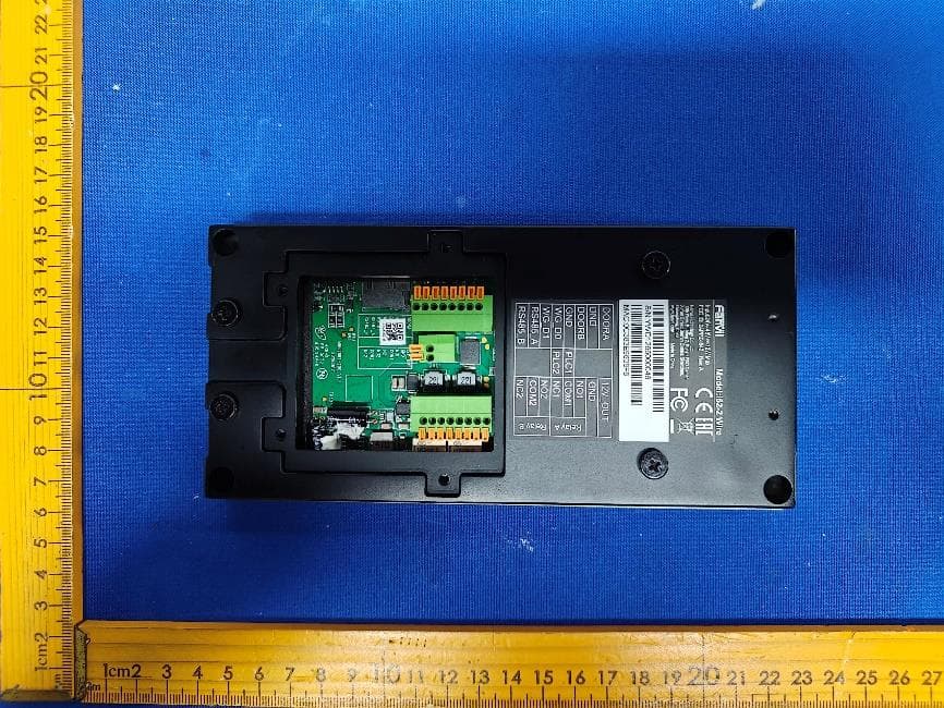
2BCUQ-I642
Sep 10, 20262 Wire Video Door Phone
Equipment Class
DXX - Part 15 Low Power Communication Device Transmitter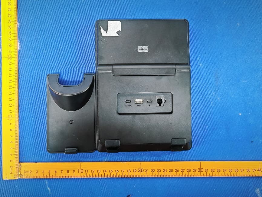
2BCUQ-DB36
Aug 12, 2026USB Workstation
Equipment Class
DTS - Digital Transmission System2BCUQ-W626W
Aug 06, 2026Wi-Fi Phone
Equipment Class
DTS - Digital Transmission System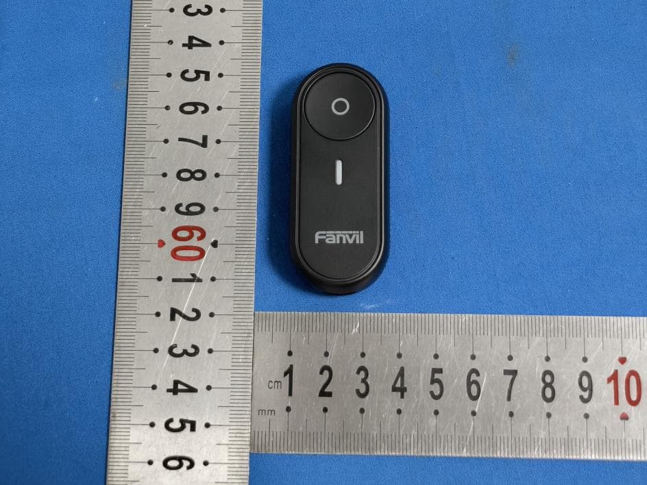
2BCUQ-BK01
Jun 22, 2026Bluetooth Key
Equipment Class
DTS - Digital Transmission System